

Page 1

OGi Modem
Hardware Guide
T401, Version .15
© ORBCOMM Proprietary
Jan 2016
Page 2

OGi Modem - Hardware Guide
Legal Notice
This documentation is owned by ORBCOMM and protected by applicable copyright laws and international
treaty provisions. Other copyrighted names used are the property of their respective owners. Therefore, you
must treat this documentation like any other copyrighted material. You may not make the documentation, or
copies thereof, available in any manner or form, or use, copy or transfer any part, to anyone outside your
company.
If you received this documentation by electronic transmission or download, by installation or use of the
documentation, you acknowledge that you have read and understand this license agreement and agree to be
bound by its terms and conditions.
This documentation is provided on an as-is basis without any warranty of any kind. You assume the entire risk
as to the results or performance of the software. Under no circumstance shall ORBCOMM be held liable for
any direct, indirect, consequential, or incidental damages arising from the use or inability to use the software
or documentation.
All trademarks or registered trademarks are the property of their respective owners. INMARSAT, the Inmarsat
logo and IsatData Pro are trademarks of Inmarsat used under license by SkyWave (an ORBCOMM company).
Inmarsat is not responsible for the operation and regulatory compliance of the products and services referred
to in this document that connect to the Inmarsat system.
ORBCOMM reserves the right to make changes to products and or specifications without notice.
Contact Information
SkyWave Mobile Communications Inc., an ORBCOMM company
Online:
Website www.SkyWave.com
Online Documentation:
Login at support.skywave.com and follow the link to the downloads section
Customer Support by Email:
Customer Support by Telephone:
+1.613.836.2222
Documentation Feedback:
The Customer Documentation Department creates the technical manuals. Use the
address below to tell us what you think about our technical documentation and if you
have suggestions for improvement.
In your feedback please reference a specific document number or title. We read all
feedback carefully, but please note that we cannot respond to the comments you
submit. If you require technical assistance, please contact Customer Support.
T401, Version .15 ii © ORBCOMM Proprietary
Page 3

OGi Modem - Hardware Guide
TABLE OF CONTENTS
Legal Notice .................................................................................................................................... ii
Contact Information ...................................................................................................................... ii
List of Figures ................................................................................................................................ v
List of Tables .................................................................................................................................. v
Preface ........................................................................................................................................... vi
Purpose ........................................................................................................................................ vi
Errata Sheet .................................................................................................................................. vi
Audience ...................................................................................................................................... vi
Notation ....................................................................................................................................... vi
Reference ..................................................................................................................................... vi
Safety Disclaimer ......................................................................................................................... vi
Environmental Protection ........................................................................................................... vii
Safety Precautions....................................................................................................................... vii
Limited Liability ......................................................................................................................... vii
Certification ................................................................................................................................ vii
Warranty .................................................................................................................................... viii
1 Overview .............................................................................................................................. 9
1.1 Overview of the Messaging System ................................................................................... 9
1.2 OGi Modem ...................................................................................................................... 10
1.2.1 Remote Antennas ........................................................................................................ 10
1.2.2 Unpackaged Antennas ................................................................................................. 11
1.3 Key Features and Benefits ................................................................................................ 12
1.4 Operating Modes .............................................................................................................. 12
1.4.1 Satellite Modem .......................................................................................................... 12
1.4.2 GNSS Receiver ........................................................................................................... 12
2 Compliance ........................................................................................................................ 13
3 Specifications ..................................................................................................................... 14
3.1 Connector ......................................................................................................................... 14
3.1.1 Pin Designations.......................................................................................................... 14
3.1.2 Pin Descriptions .......................................................................................................... 14
3.2 RF Connector ................................................................................................................... 15
3.3 RF Connection Specifications .......................................................................................... 16
3.4 Power ................................................................................................................................ 16
3.4.1 Average Power Consumption ..................................................................................... 16
3.4.2 Inrush Current ............................................................................................................. 16
3.5 Serial Interface ................................................................................................................. 17
3.5.1 Master Reset ................................................................................................................ 17
3.6 Frequency ......................................................................................................................... 17
3.7 Antenna Specifications ..................................................................................................... 17
3.7.1 Standard Antenna ........................................................................................................ 18
3.7.2 Low Elevation Antenna ............................................................................................... 18
3.8 Multi-GNSS ..................................................................................................................... 18
3.8.1 1PPS Signal ................................................................................................................. 18
3.9 Mechanical Properties ...................................................................................................... 18
© ORBCOMM Proprietary iii T401, Version .15
Page 4

OGi Modem - Hardware Guide
3.9.1 OGi Modem ................................................................................................................ 18
3.9.2 Packaged Antenna – Standard ..................................................................................... 19
3.9.3 Packaged Antenna – Low Elevation ........................................................................... 19
3.9.4 Unpackaged Antenna – Standard ................................................................................ 19
3.9.5 Unpackaged Antenna – Low Elevation ....................................................................... 19
3.10 Physical Dimensions ........................................................................................................ 20
3.10.1 OGi Modem ................................................................................................................ 20
3.10.2 Packaged Antenna - Standard ..................................................................................... 22
3.11 Environmental .................................................................................................................. 26
3.12 Mobile Identification Number .......................................................................................... 28
4 Integration Guidelines ...................................................................................................... 29
4.1 Regulatory Guidelines ...................................................................................................... 29
4.2 Compliance ....................................................................................................................... 29
4.2.1 Reference Power Supply ............................................................................................. 29
4.2.2 Review Process ........................................................................................................... 29
4.3 EMI/EMC Guidelines ....................................................................................................... 29
4.3.1 Typical Integration ...................................................................................................... 30
4.3.2 Antenna Cable Guidelines ........................................................................................... 30
4.3.2.1 General Guidelines for Antenna Positioning .......................................................................30
4.3.3 Host Shielding ............................................................................................................. 30
4.3.4 Decoupling .................................................................................................................. 31
4.4 Maximum Current ............................................................................................................ 31
4.5 Enclosure Design .............................................................................................................. 31
4.5.1 Label Guidelines ......................................................................................................... 32
4.5.2 Mating Connector Guidelines ..................................................................................... 32
4.6 Modem Mounting Guidelines........................................................................................... 32
4.7 Unpackaged Antenna Mounting Guidelines .................................................................... 33
5 Antenna Installation ......................................................................................................... 34
5.1 Antenna Mounting Guidelines ......................................................................................... 34
5.2 Mount a Remote Antenna ................................................................................................. 35
5.2.1 Screw Mount ............................................................................................................... 35
5.2.2 Adhesive Mount .......................................................................................................... 36
5.2.2.1 Silicone Side Connector Mount ..........................................................................................37
5.2.2.2 Silicone Bottom Connector Mount ......................................................................................38
APPENDIX A Order Part Numbers ....................................................................................... 41
APPENDIX B Remote Antenna Template ............................................................................. 42
Acronyms/Glossary ..................................................................................................................... 43
Revision History .......................................................................................................................... 44
T401, Version .15 iv © ORBCOMM Proprietary
Page 5

OGi Modem - Hardware Guide
List of Figures
Figure 1 Messaging Gateway ...................................................................................................... 9
Figure 2 OGi Modem ................................................................................................................ 10
Figure 3 Antennas ...................................................................................................................... 11
Figure 4 Antenna Bottom Mount (standard antenna shown) ..................................................... 11
Figure 5 Unpackaged Standard Antenna ................................................................................... 11
Figure 6 Unpackaged Low Elevation Antenna .......................................................................... 12
Figure 7 Modem Connector Pinout - Top View of Modem (odd numbers) .............................. 14
Figure 8 Modem Connector Pinout - Bottom View of Modem (even numbers) ....................... 14
Figure 9 Top View Dimensions (mm) ....................................................................................... 20
Figure 10 Side Views (mm) ....................................................................................................... 21
Figure 11 Bottom View ............................................................................................................. 21
Figure 12 Packaged Antenna (Standard and Low Elevation) - Bottom View (mm) ................. 22
Figure 13 Packaged Standard Antenna Height Dimensions (mm) ............................................ 22
Figure 14 Packaged Low Elevation Antenna Height Dimensions (mm) ................................... 23
Figure 15 Standard Unpackaged Antenna – Top View (mm).................................................... 23
Figure 16 Standard Unpackaged Antenna – Side View (mm) ................................................... 24
Figure 17 Unpackaged Antenna (Standard and Low Elevation) – Bottom View (mm) ............ 24
Figure 18 Unpackaged Antenna (Low Elevation) – Top View (mm) ....................................... 25
Figure 19 Unpackaged Antenna (Low Elevation) – Side View (mm) ....................................... 25
Figure 20 Mobile ID Location ................................................................................................... 28
Figure 21 Typical OEM Integrator Modem Design ................................................................... 30
Figure 22 Modem Mounting Holes ............................................................................................ 32
Figure 23 Antenna Cable Bend Radius ...................................................................................... 35
Figure 24 Air Vent Feature ........................................................................................................ 36
Figure 25 Air Vent Feature ........................................................................................................ 37
Figure 26 Apply Silicone to Remote Antenna ........................................................................... 37
Figure 27 Drill Mounting Hole .................................................................................................. 38
Figure 28 Attach Cable to Antenna ........................................................................................... 39
Figure 29 Apply Silicone to Hole in Asset ................................................................................ 39
Figure 30 Apply Silicone to Terminal ....................................................................................... 40
List of Tables
Table 1 Satellite Modem Operating Modes ............................................................................. 12
Table 2 Modem Electrical Pin Assignment .............................................................................. 14
Table 3 Typical Power Consumption (current) ........................................................................ 16
Table 4 Multi-GNSS Typical Specifications............................................................................ 18
© ORBCOMM Proprietary v T401, Version .15
Page 6
OGi Modem - Hardware Guide
Preface
Purpose
This document provides an overview of the hardware characteristics and specifications
for the OGi modem.
Errata Sheet
Refer to the SkyWave Customer Support website for updates or for an Errata Sheet that
might be available after the release of this document. Always check the website for the
most current documentation.
Audience
This document is for technical readers. It provides information to ensure successful
integration of the OGi modem.
Notation
An OEM Integrator is an ORBCOMM customer who purchases an OGi modem for
integration into their own enclosure. To become an OEM Integrator certain commercial
criteria must be met. Contact your Account Executive for further details.
Hardware components and hardware labels in this document might not be exactly as
shown and are subject to change without notice.
CAUTION This safety symbol warns of possible hazards to personnel,
equipment, or both. It includes hazards that will or can cause
personal injury, property damage, or death if the hazard is not
avoided.
Note: A note indicates information with no potential hazard. A note indicates points
of interest or provides supplementary information about a feature or task.
Numbered lists indicate a series of steps required to complete a task or function.
Bulleted lists highlight information where order or sequence is not crucial.
Reference
The content of the following documents might be useful in conjunction with this guide.
These documents are available from the downloads section at support.skywave.com or
from the OG Toolkit, which is also available from the website.
[T402] OG Interface Developer Guide
[T403] AT Interface Developer Guide
Safety Disclaimer
ORBCOMM makes no warranties, representations or guarantees that the products and
network services are suitable for any use in any hazardous environments requiring fail
T401, Version .15 vi © ORBCOMM Proprietary
Page 7

OGi Modem - Hardware Guide
safe performance (including without limitation marine safety and distress systems,
operation of nuclear facilities, aircraft navigation or communications systems, weapons
systems, air traffic control and life support services) or any other application in which the
failure of the products or network services could result in death or personal injury.
Purchasers assume all liability associated with selling any products and network services
for any such applications, and the Purchaser will defend, indemnify, and hold
ORBCOMM harmless against any claims against ORBCOMM for loss, damage, liability,
or expense (including lawyers’ fees) arising out of or related to the sale by Purchasers or
any Reseller, or the use by any end user, of any product or network service.
Please read all cautions and warnings throughout this document.
Environmental Protection
The Purchaser’s enclosure must provide environmental protection for the OG ISAT
modem.
Safety Precautions
The terminal must comply with all safety precautions relating to the operation, usage,
service and repair of the terminal. ORBCOMM assumes no liability for the customer’s
failure to comply with any of these precautions.
Caution warnings appear throughout this document.
Limited Liability
ORBCOMM’s liability is limited to the cost of repair or replacement of any of
ORBCOMM’s products during the warranty period. To the maximum extent permitted by
applicable law, ORBCOMM’s total liability for damages of any kind, whether based on
breach of contract, tort (including negligence), product liability, incidental, special,
consequential, indirect or similar damages with product application and usages will be
limited to an amount equal to the product's original price paid by the Purchaser to
ORBCOMM and this limitation of liability is reasonable given the price of ORBCOMM's
products. In no event will ORBCOMM be liable to the Purchaser, any resellers of the
Purchaser or any end user for any lost profits or savings, lost business, loss of data, any
telecommunications breakdown, unavailability, downtime, interruption or delay, any
suspension of service by any third party service provider including Inmarsat or any
incidental, special, indirect, or consequential damages, whether based on breach of
contract, tort (including negligence), product liability, incidental, special, consequential,
indirect or similar damages and whether or not ORBCOMM has been advised of the
possibility of such occurrence or damage. The parties agree that the foregoing represents
a fair allocation of risk hereunder.
Certification
The Purchasers is responsible for ensuring that the Purchaser's integrated product
complies with all local electrical and safety codes. The Purchaser is also responsible for
certifying all of their integrated products.
© ORBCOMM Proprietary vii T401, Version .15
Page 8

OGi Modem - Hardware Guide
Warranty
ORBCOMM provides a manufacturer’s warranty to the original purchaser (Purchaser)
that its products and services will perform in accordance with ORBCOMM’s
specifications and will be free from defects in material and workmanship for a limited
period of time. This warranty is limited to the repair and/or replacement of any defective
components experienced under normal specified operating use and storage conditions, at
ORBCOMM’s discretion. It does not cover any damages caused or associated with the
product’s misuse. Please check your agreement for warranty details and conditions. The
end-user’s only remedy or recourse is against the Purchaser, and any experience with
defective products should be communicated to the authorized distributor from whom they
have been purchased. Shipping of defective product, back to the authorized distributor
will be in accordance with the authorized distributor's instructions and should be
accompanied with a fault report. ORBCOMM is not responsible for corrosion damage
caused by inadequate enclosure or cable assembly or installation. Warranty is void if
unit is opened.
A fault report is required for each unit returned under warranty. Please contact your
authorized distributor's customer support for additional information.
T401, Version .15 viii © ORBCOMM Proprietary
Page 9
OGi Modem - Hardware Guide
Solution Provider
and Customer Site
Internet
Gateway
Land Earth
Station (LES)
Satellite
OGi Modem
GPS
Satellites
Computer
1 Overview
The OGi modem is an L-Band mobile device and provides either an AT interface or an
OG interface for command and control. Hardware using an AT interface operates on the
IsatData Pro gateway while hardware using an OG interface operates on the ORBCOMM
gateway. ORBCOMM’s turn-key OEM solutions are intended for early integration into
M2M applications.
An OGi modem contains a satellite transceiver and a GNSS receiver, and requires a
specific passive antenna. The modem accepts commands and returns responses via a
serial interface.
The modem is suitable for both industrial and fixed applications such as:
Transportation and Distribution
Fleet management and security
Asset tracking, monitoring and control
1.1 Overview of the Messaging System
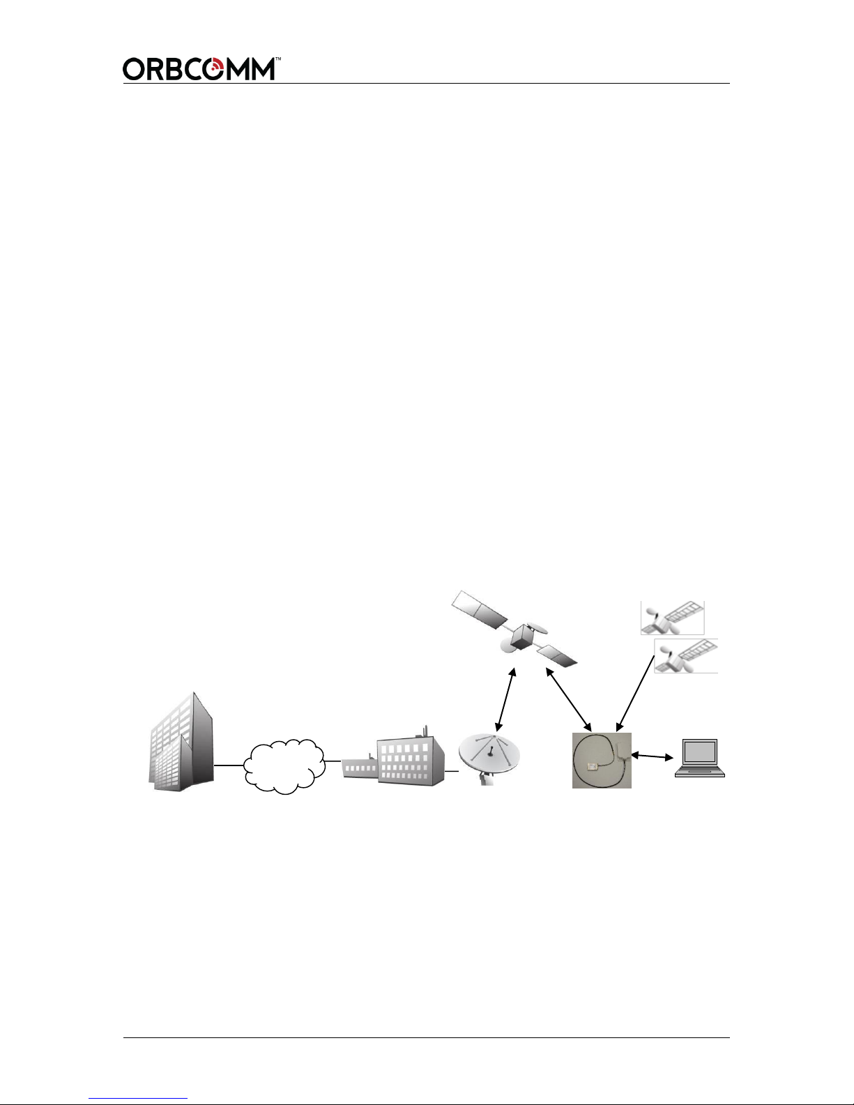
The IsatData Pro service allows OEM Integrators to offer particular applications and/or
services to their clients. As shown in Figure 1, the OEM Integrator communicates with
the modem through a centralized gateway. The gateway is the communications hub of the
system, controlling access to the modem and routing traffic to the modem, regardless of
where it is deployed in the world.
Figure 1 Messaging Gateway
Configuration and data retrieval from the modem can be easily accomplished through
Internet-based application services provided by OEM Integrators or by integrating
existing customer enterprise software to receive information from the Gateway.
IsatData Pro provides the following key features and benefits:
Two-way communication
Messaging to a host connected to the modem
© ORBCOMM Proprietary 9 T401, Version .15
Page 10
OGi Modem - Hardware Guide
Broadcast messages
Low latency messaging
Up to 6,400 bytes from-mobile messages for the AT Interface; up to 6,000 bytes
from-mobile messages for the OG Interface
Up to 10,000 bytes to-mobile messages for the AT Interface; to-mobile messages
for the OG Interface are truncated
Acknowledged messages
Global service
1.2 OGi Modem
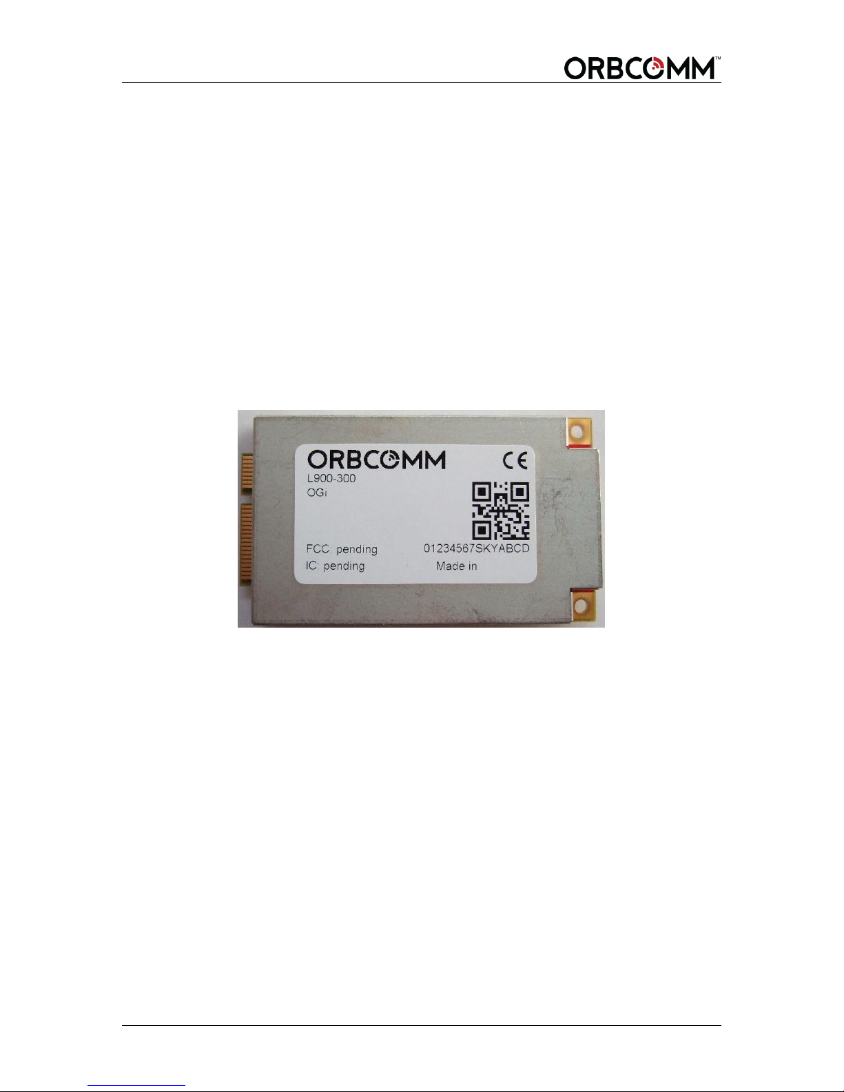
The OGi modem provides easy integration and the highest level of EMI/EMC shielding
that reduces integration risk when the modem is co-located with other electronics.
Figure 2 OGi Modem
1.2.1 Remote Antennas
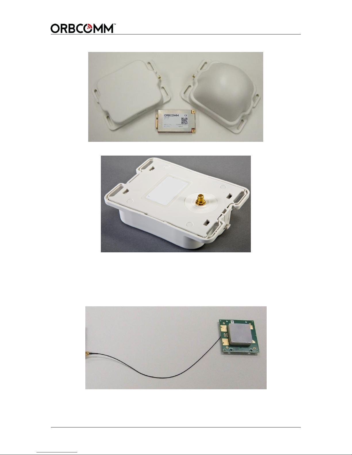
Two passive antenna types are available: a standard antenna (Figure 3) and a low
elevation antenna (Figure 3). The standard antenna has an elevation angle of 20 to 90°
and the low elevation antenna has an elevation angle of -15 to 90°. The OEM Integrator
is responsible for providing a specific RF cable to connect the antenna to the modem.
Both the standard and low elevation antennas are:
Available with a side or bottom connector
Sealed for operating in outdoor environments
Provide four mounting tabs for installation
Available with an SMA connector
Available packaged or unpackaged
T401, Version .15 10 © ORBCOMM Proprietary
Page 11
OGi Modem - Hardware Guide
Standard
Antenna
Low Elevation
Antenna
Figure 3 Antennas
Figure 4 Antenna Bottom Mount (standard antenna shown)
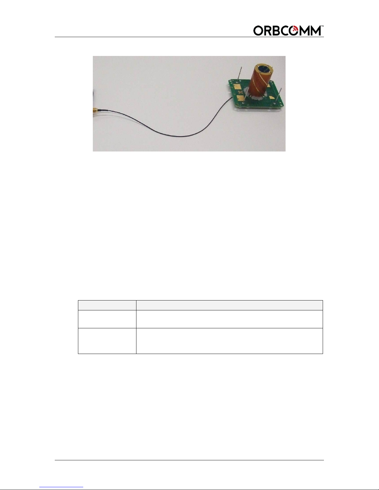
1.2.2 Unpackaged Antennas
Both antenna types, standard and low elevation, are also available in an unpackaged
form. Both feature an IPX connector for connection to the modem and four mounting
holes for installation.
Figure 5 Unpackaged Standard Antenna
© ORBCOMM Proprietary 11 T401, Version .15
Page 12
OGi Modem - Hardware Guide
Operating Mode
Description
Transmit Mode
In transmit mode the modem is transmitting a signal to the
gateway.
Receive Mode
In receive mode the modem is attempting or actively listening to
the satellite (listening on the bulletin board channel or on a traffic
channel).
Figure 6 Unpackaged Low Elevation Antenna
1.3 Key Features and Benefits
The OGi modem offers the following key features and benefits:
Designed to be incorporated into an OEM Integrator's solution
Built-in GNSS receiver to provide position, speed and heading information
Broad operational temperature range
IsatData Pro message payload and latency capabilities
1.4 Operating Modes
1.4.1 Satellite Modem
For the most part, the modem operates independently from the host application. The
modem operating modes are described in Table 1.
Table 1 Satellite Modem Operating Modes
1.4.2 GNSS Receiver
The GNSS receiver is a module peripheral that is either on or off.
T401, Version .15 12 © ORBCOMM Proprietary
Page 13

OGi Modem - Hardware Guide
1
2 Compliance
At this time, all certifications listed in this section are pending for the OGi modems.
Once approved, these certifications and test results will be available to OEM Integrators
for use as a baseline for the certification approval of their enclosure.
However, the OEM Integrator is responsible for ensuring that their final enclosure
complies with all local regulatory requirements, and electrical and safety codes wherever
the enclosures are sold or used. As the OEM Integrator’s enclosure contains the OEM
Integrator’s power supply and possibly other circuitry that affects the modem, the OEM
Integrator most likely needs to perform additional testing or repeat some of the tests listed
below.
Inmarsat Type Approval
Industry Canada RSS-170
Pending
FCC Part 25
CFR Title 47: Telecommunication, Part 25 - Satellite Communications
CE Mark
EN 301 426
RoHS
Restriction of Hazardous Substances (RoHS)1
European Union's (EU) Directive 2002/95/EEC "Restriction of Hazardous Substances" (RoHS)
in Electronic and Electrical Equipment.
© ORBCOMM Proprietary 13 T401, Version .15
Page 14
OGi Modem - Hardware Guide
Parameter
Value
Connector
Mini PCI express, 0.8 mm pitch, 52 pin connectors with 26 per side, with
gold plated contacts. Several heights are available from multiple vendors.
TE Connectivity 1775838-2
FCI 10123908
Pin
Name
I/O
Voltage
Description
1
Reserved
- - Do not connect
2
MAIN_POWER
I
5.0 – 15.0 VDC
-
3
Reserved
- - Do not connect
4
GND
- - Ground
5
MASTER_RX
I - 3.3 V logic levels
6
Reserved
- - Do not connect
7
MASTER_TX
O - 3.3 V logic levels
8
Reserved
- - Do not connect
Pin 1
Pin 2
3 Specifications
3.1 Connector
The table below describes the mating connector.
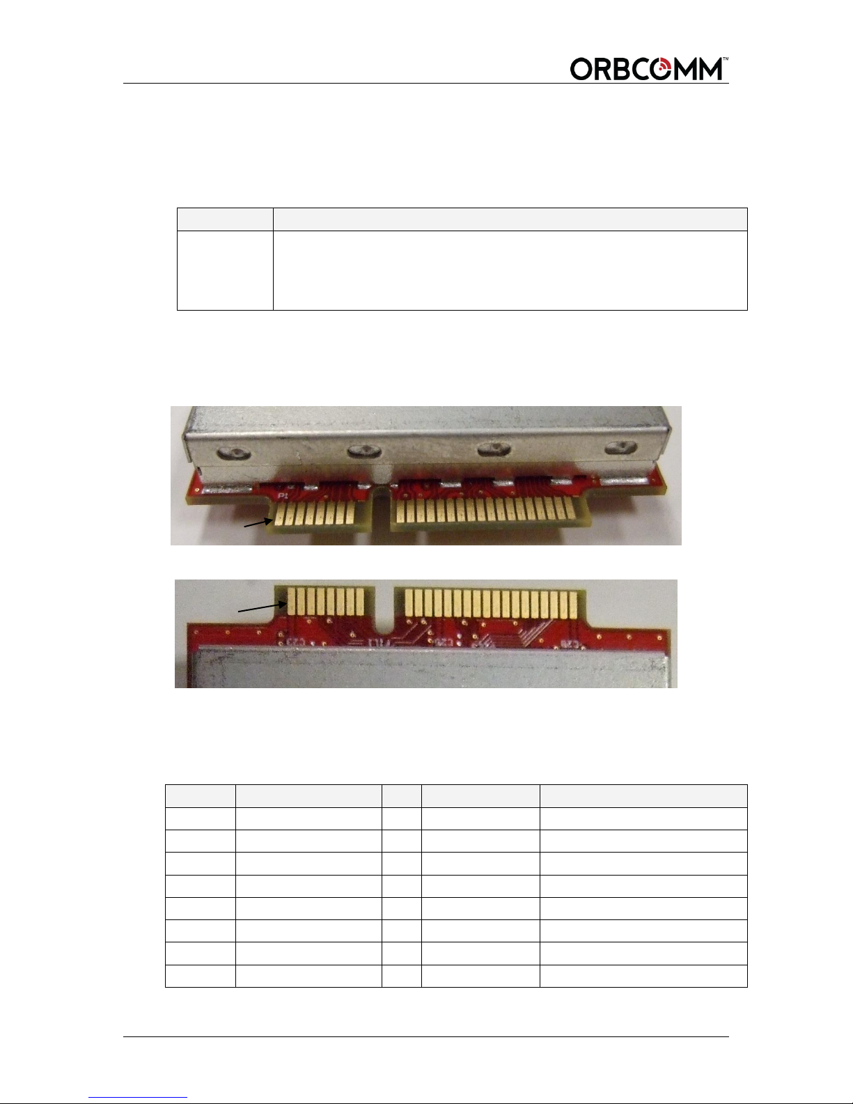
3.1.1 Pin Designations
Figure 7 shows the pin number designations.
Figure 7 Modem Connector Pinout - Top View of Modem (odd numbers)
Figure 8 Modem Connector Pinout - Bottom View of Modem (even numbers)
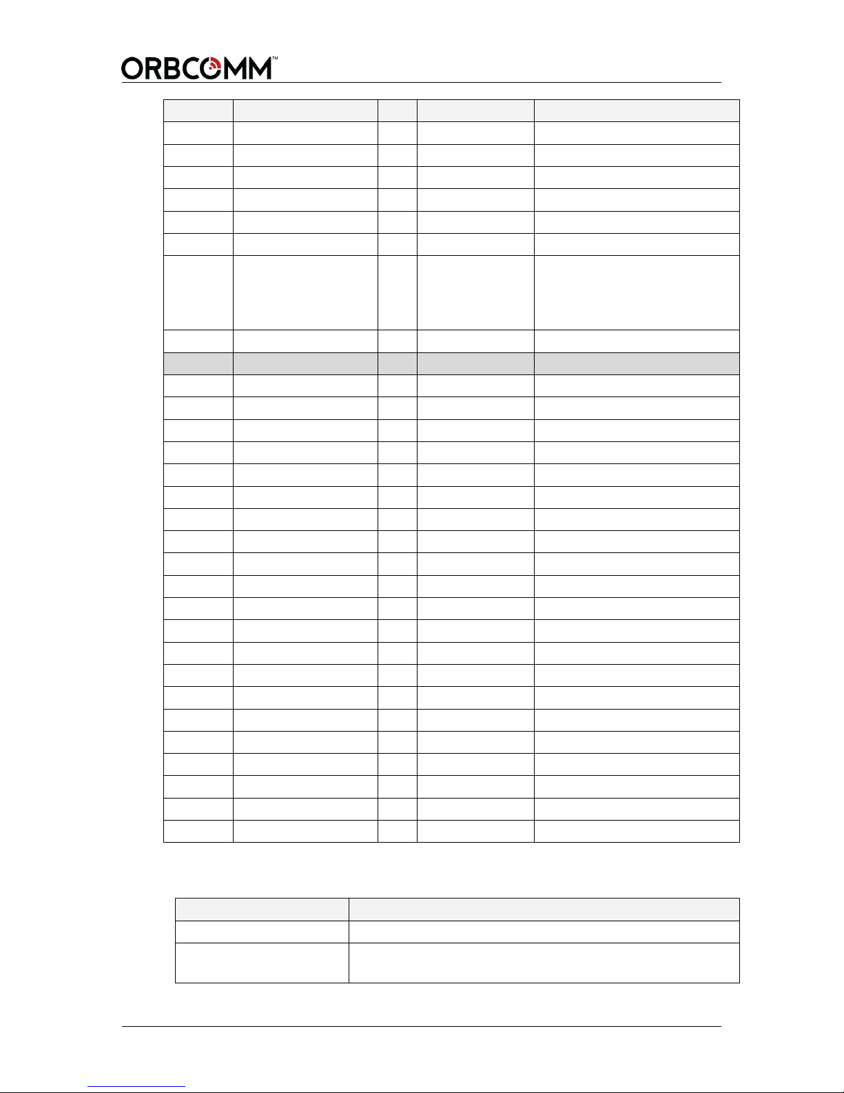
3.1.2 Pin Descriptions
Table 2 contains the modem pin assignments.
Table 2 Modem Electrical Pin Assignment
T401, Version .15 14 © ORBCOMM Proprietary
Page 15
OGi Modem - Hardware Guide
Pin
Name
I/O
Voltage
Description
9
GND
- - Ground
10
Reserved
- - Do not connect
11
DEBUG_RX
I - 3.3 V logic levels
12
Reserved
- - Do not connect
13
DEBUG_TX
O - 3.3 V logic levels
14
Reserved
- - Do not connect
15
MASTER_RESET
I - High impedance, active low
internal 10 kΩ pull-up, pulldown with field effect
transistor.
16
Reserved
- - Do not connect
17
Reserved
- - Do not connect
18
GND
- - Ground
19, 20
Reserved
- - Do not connect
21
GND
- - Ground
22, 23
Reserved
- - Do not connect
24
MAIN_POWER
I
5.0 – 15.0 VDC
Input voltage
25
Reserved
- - Do not connect
26
GND
- - Ground
27
GND
- - Ground
28
Reserved
- - Do not connect
29
GND
- - Ground
30
1PPS
O
3.3 V logic level
Output
31…33
Reserved
- - Do not connect
34
GND
- - Ground
35
GND
- - Ground
36…39
Reserved
- - Do not connect
40
GND
- - Ground
41…49
Reserved
- - Do not connect
50
GND
- - Ground
51
Reserved
- - Do not connect
52
MAIN_POWER
I
5.0 – 15.0 VDC
Input voltage
Parameter
Value
Modem RF Connector
MMCX, female (jack) connector
Unpackaged Antenna RF
Connector
IPEX (U.FI) SMT receptacle
3.2 RF Connector
© ORBCOMM Proprietary 15 T401, Version .15
Page 16
OGi Modem - Hardware Guide
Parameter
Value
Packed/Remote Antenna
RF Connector
SMA female
Parameter
Minimum
Typical
Maximum
Units
RF Output
30.5
31.5
32.5
dBm
Parameter
Minimum
Maximum
Units
MAIN_POWER
5
15
VDC
Parameter
Current
@ 5 VDC
@ 8 VDC
@ 12 VDC
GPS Fix
150 mA
100 mA
70 mA
Satellite communications receive
170 mA
110 mA
80 mA
Transmit
2000 mA
1050 mA
750 mA
Typical Inrush Current on MAIN_POWER at 5 V
Amplitude (mA)
Period (µs)
Charge (µC)
Power Up
500
4000
3000
GPS Power Up
150
500
50
Receive Power Up
200
160
100
Transmit Power Up
3000
3700
3000
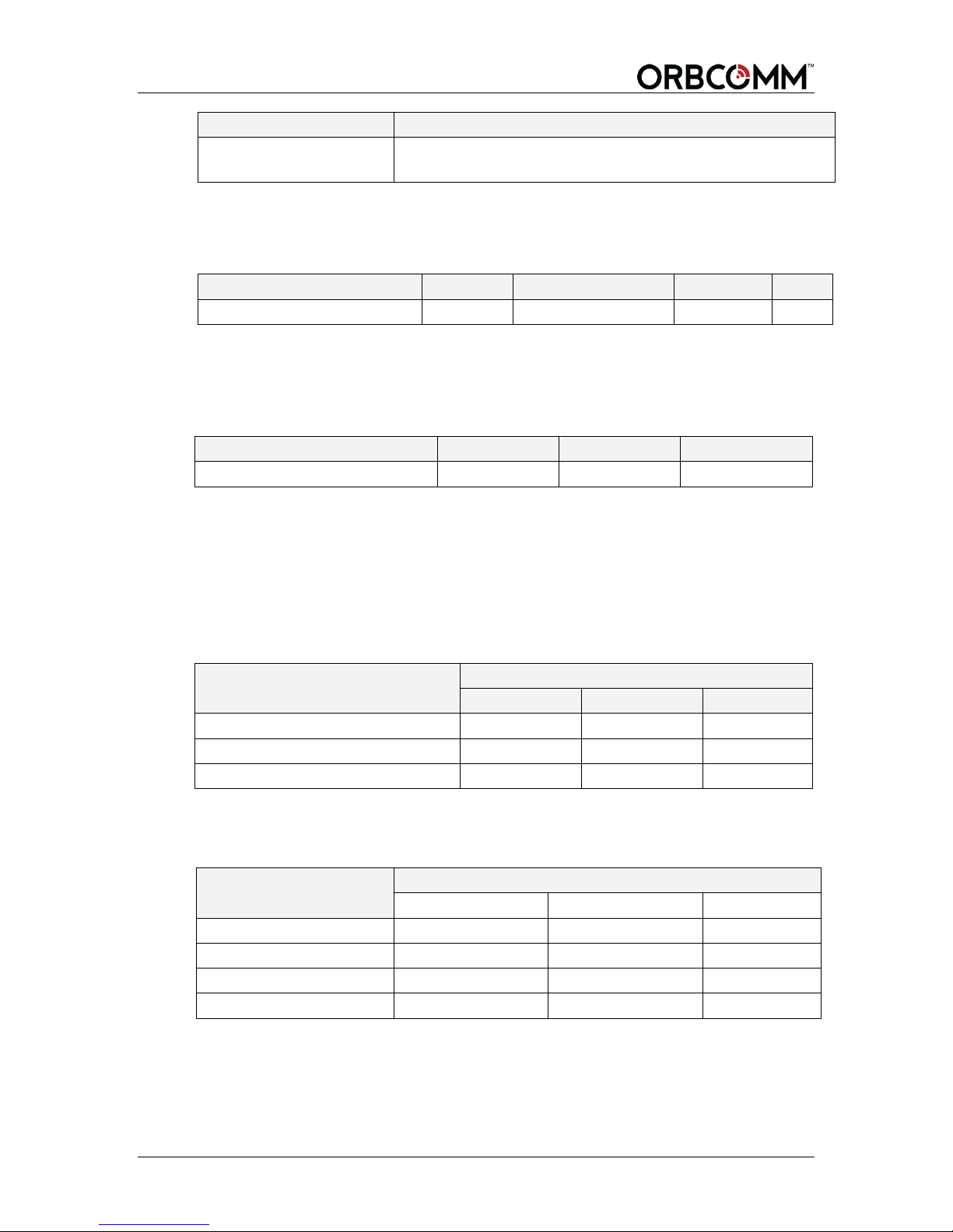
3.3 RF Connection Specifications
The table below lists the specification for the RF present on the RF connector.
3.4 Power
The modem has various power pins as shown in Table 2. Power input must always be
present on all power pins.
3.4.1 Average Power Consumption
When the modem is on, its default and steady state is satellite communications receive
current, unless it is transmitting or acquiring a GPS fix.
Table 3 shows power averages, at room temperature (22°C), taken from startup to
registration, for three MAIN__POWER voltage.
Table 3 Typical Power Consumption (current)
3.4.2 Inrush Current
The modem's inrush specifications for MAIN_POWER are shown in the tables below.
T401, Version .15 16 © ORBCOMM Proprietary
Page 17
OGi Modem - Hardware Guide
Typical Inrush Current on MAIN_POWER at 12 V
Amplitude (mA)
Period (µs)
Charge (µC)
Power Up
700
3000
400
GPS Power Up
80
350
50
Receive Power Up
90
200
60
Transmit Power Up
900
3000
1100
Parameter
Minimum
Typical
Maximum
Units
DEBUG_RX input
2.7
3.3
3.6
VDC
MASTER_RX input
2.7
3.3
3.6
VDC
DEBUG_TX output
2.7
3.3
3.6
VDC
MASTER_TX output
2.7
3.3
3.6
VDC
Parameter
Maximum
Units
MASTER_RESET pulled high
3.3
V
MASTER_RESET
<500
µA
Parameter
Value
Receive frequency band
(to-mobile)
1525 to 1559 MHz, channel bandwidth 5 kHz
1518 to 1525 MHz, channel bandwidth 5 kHz
Transmit frequency band
(from-mobile)
1626.5 to 1660.5 MHz, channel bandwidth 2 kHz
1668 to 1675 MHz, channel bandwidth 2 kHz
GNSS Band
GPS L1; GLONASS L1; BeiDou B1
3.5 Serial Interface
The serial defaults to the following settings: 9600 bit/s (8 data, no parity, 1 stop bit) with
debug default of 115,200 bit/s (8 data, no parity, 1 stop bit).
The master and debug ports are configurable. Voltages for these ports are 3.3 VDC
CMOS logic levels.
3.5.1 Master Reset
The MASTER_RESET resets the modem to its default startup state. The
MASTER_RESET pin is open drain and has an internal 10 KΩ pull-up.
3.6 Frequency
The table below lists the modem's operating frequencies.
3.7 Antenna Specifications
The antenna is available in two types: standard and low elevation.
© ORBCOMM Proprietary 17 T401, Version .15
Page 18
OGi Modem - Hardware Guide
Parameter
Value
Elevation angle
> 20 degrees elevation
Maximum transmit passive antenna gain
4.5 dBic
Parameter
Value
Elevation angle
-15 degrees elevation
Maximum transmit passive antenna gain
2.5 dBic
Parameter
GPS
GPS/
GLONASS
GPS/BeiDou
Time to First Fix2
Cold Start
30s
27s
28s
Hot Start
1s
1s
1s
Sensitivity
Tracking
-163 dBm
-164 dBm
-162 dBm
Hot Start
-156 dBm
-156 dBm
-156 dBm
Cold Start
-147 dBm
-147 dBm
-147 dBm
Accuracy
Horizontal Position (CEP) 3
-
2.5/2.0 m
-
Velocity
-
0.05 m/s
-
Heading
-
0.3 degrees
-
Parameter
Value
Mass
20 g
2
3
3.7.1 Standard Antenna
3.7.2 Low Elevation Antenna
3.8 Multi-GNSS
Table 4 Multi-GNSS Typical Specifications
3.8.1 1PPS Signal
The 1PPS signal is available in the modem. It outputs a pulse per second by default,
provided a valid GPS signal is present. If the GPS signal is blocked, the 1PPS stops.
By default the GPS is only on when requested by the application or the network. For
constant time updates, the GPS must be on at all times.
3.9 Mechanical Properties
3.9.1 OGi Modem
All satellites at -130 dBm
CEP, 50%, 24 hours static, -130 dBm, >6 SVs
T401, Version .15 18 © ORBCOMM Proprietary
Page 19
OGi Modem - Hardware Guide
Parameter
Value
Mass (excludes cable, side entry version)
360 g
Enclosure Material
Lexan EXL 9330
Parameter
Value
Mass (excludes cable, side entry version)
367 g
Enclosure Material
Lexan EXL 9330
Parameter
Value
Mass
92 g
UV Resistance
No inherent UV stability
Parameter
Value
Mass
68 g
UV Resistance
No inherent UV stability
3.9.2 Packaged Antenna – Standard
3.9.3 Packaged Antenna – Low Elevation
3.9.4 Unpackaged Antenna – Standard
3.9.5 Unpackaged Antenna – Low Elevation
© ORBCOMM Proprietary 19 T401, Version .15
Page 20
OGi Modem - Hardware Guide
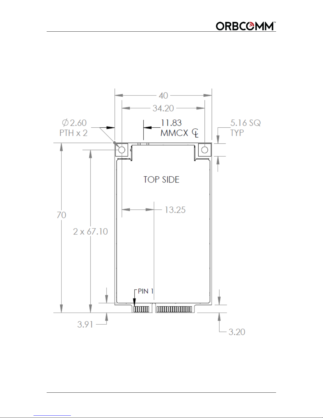
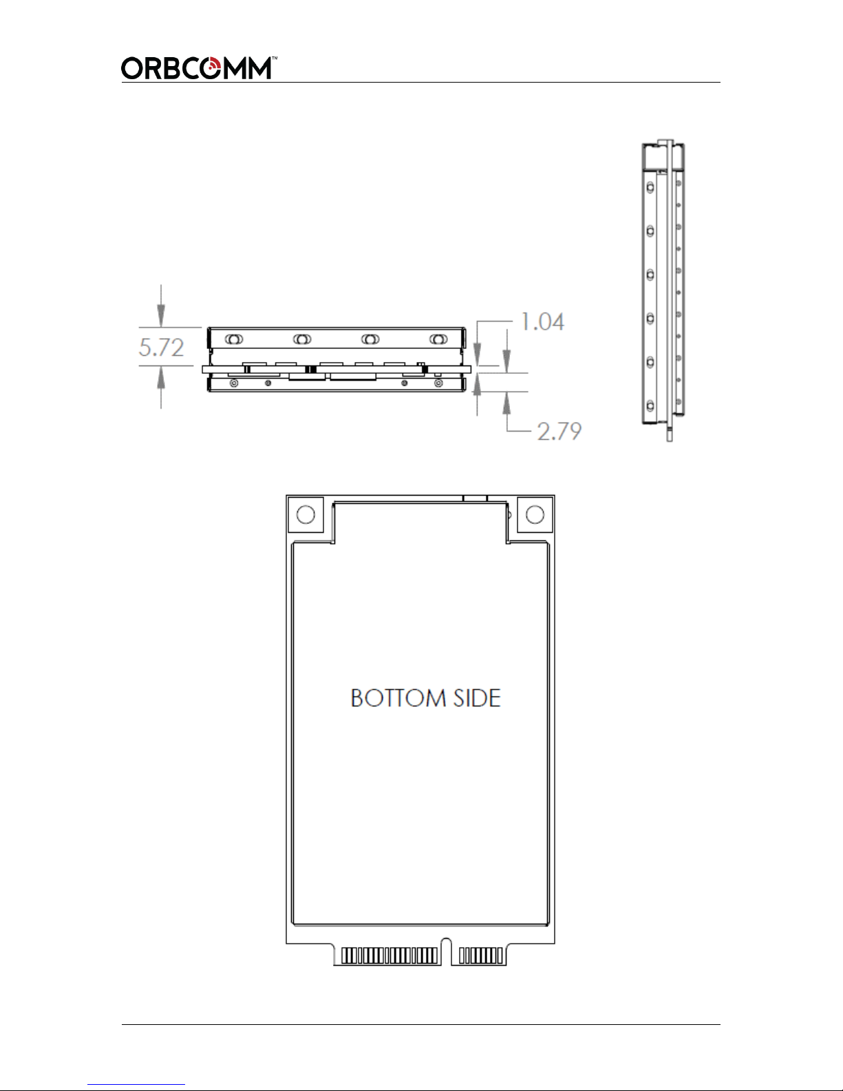
3.10 Physical Dimensions
All dimensions are shown in millimeters (mm).
3.10.1 OGi Modem
Figure 9 Top View Dimensions (mm)
T401, Version .15 20 © ORBCOMM Proprietary
Page 21
OGi Modem - Hardware Guide
Figure 10 Side Views (mm)
Figure 11 Bottom View
© ORBCOMM Proprietary 21 T401, Version .15
Page 22
OGi Modem - Hardware Guide
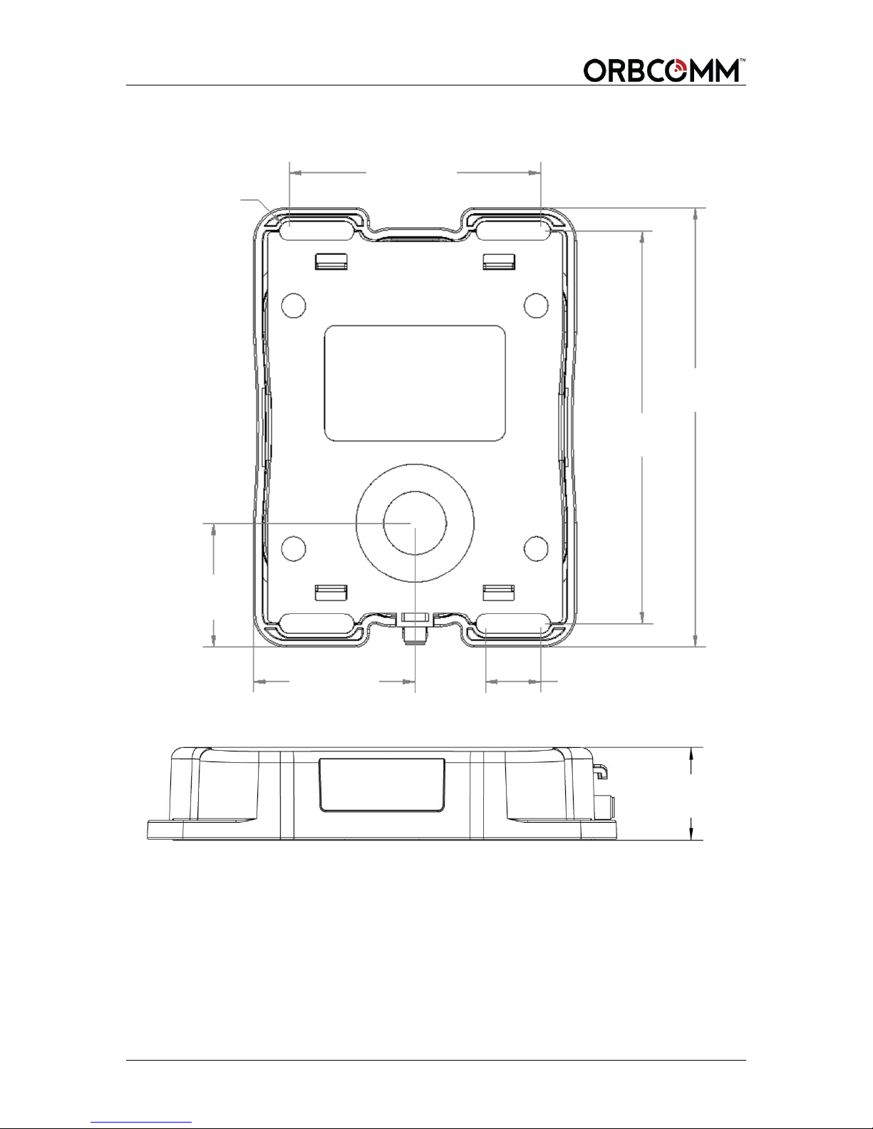
126.2±0.2
2 x 112.8
4 x 15.9
35.5±0.2
46.5±0.2
4 x 5.500
(HOLE)
2 x 72.4
25±0.3
3.10.2 Packaged Antenna - Standard
Figure 12 Packaged Antenna (Standard and Low Elevation) - Bottom View (mm)
Figure 13 Packaged Standard Antenna Height Dimensions (mm)
T401, Version .15 22 © ORBCOMM Proprietary
Page 23
OGi Modem - Hardware Guide
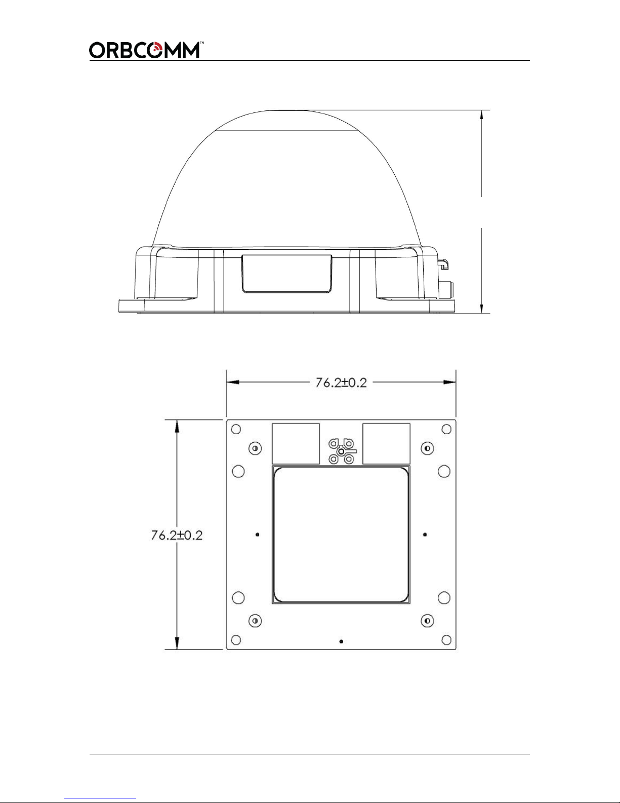
76±0.3
Figure 14 Packaged Low Elevation Antenna Height Dimensions (mm)
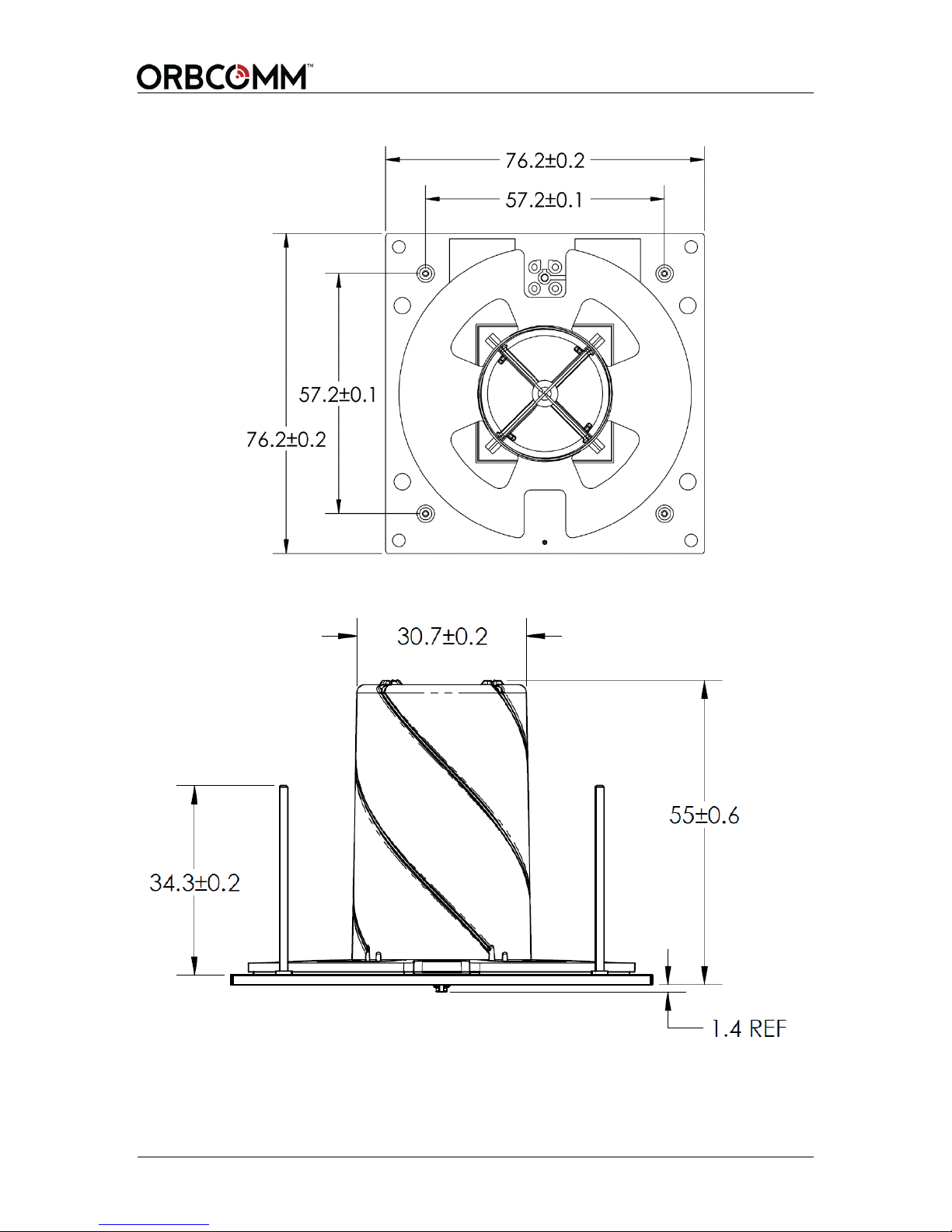
Figure 15 Standard Unpackaged Antenna – Top View (mm)
© ORBCOMM Proprietary 23 T401, Version .15
Page 24
OGi Modem - Hardware Guide
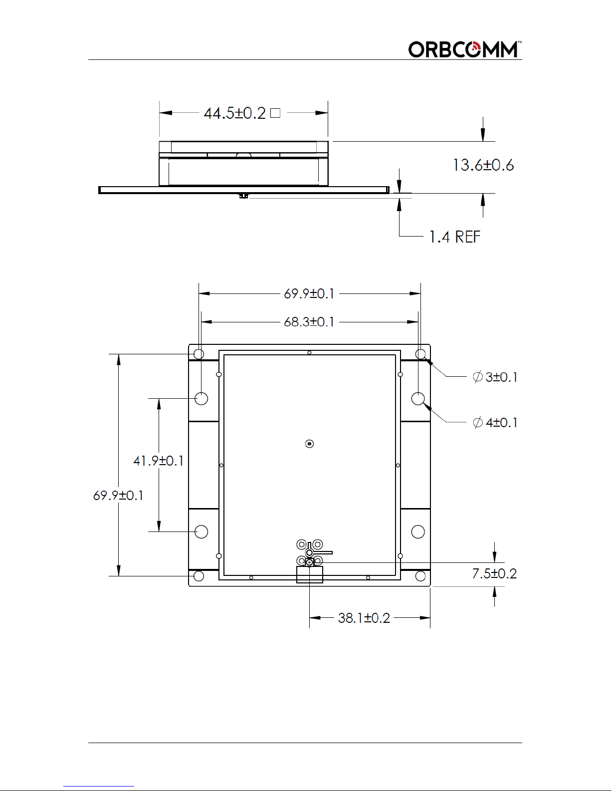
Figure 16 Standard Unpackaged Antenna – Side View (mm)
Figure 17 Unpackaged Antenna (Standard and Low Elevation) – Bottom View (mm)
T401, Version .15 24 © ORBCOMM Proprietary
Page 25
OGi Modem - Hardware Guide
Figure 18 Unpackaged Antenna (Low Elevation) – Top View (mm)
Figure 19 Unpackaged Antenna (Low Elevation) – Side View (mm)
© ORBCOMM Proprietary 25 T401, Version .15
Page 26
OGi Modem - Hardware Guide
Parameter
Value
Operating temperature range
-40°C to +85°C
Storage temperature
-40°C to +85°C
Parameter
Description
Vibration
The modem meets all its specifications during exposure to
random vehicular vibration levels per SAE J1455, section
4.10.4.2 and MIL-STD-810G, section 514.6, fig 514.6C-1.
Mechanical Shock
The modem meets all its specifications after exposure to
positive and negative saw tooth shock pulses with peaks of
20G and durations of 11 ms as specified in MIL-STD-810G,
section 516.6, Procedure I, section 2.3.2c, 3/axis/(positive and
negative direction).
Parameter
Description
Humidity
The packaged antenna meets all its specifications during
exposure to 90% relative humidity at +85°C, per the test
methodology of SAE J1455, section 4.2.3.
Vibration
The packaged antenna meets all its specifications during
exposure to random vehicular vibration levels per SAE J1455,
section 4.9.4.2 and MIL-STD-810G, section 514.6, fig 514.6C-
1.
Mechanical Shock
The packaged antenna meets all its specifications after
exposure to positive and negative saw tooth shock pulses with
peaks of 20G and durations of 11 ms as specified in MIL-STD810G, section 516.6, Procedure I, section 2.3.2c,
3/axis/(positive and negative direction).
Altitude
The packaged antenna meets all of its specifications after a
non-operating 12.2 km altitude test as detailed in SAE J1455,
section 4.9.3, except with an ambient temperature of -40°C.
Thermal Shock
The packaged antenna meets all of its specifications after a
thermal shock test as detailed in SAE J1455, section 4.1.3.2.
Salt Spray
Atmosphere
The packaged antenna meets all of its specifications after a salt
spray test as detailed in SAE J1455, section 4.3.3.1.
Immersion
The packaged antenna meets all of its specifications after a 6
hour alternating hot/cold salt water immersion test as detailed
4
3.11 Environmental4
Temperature
Modem
Packaged Antenna
The antenna is an IP67 enclosure that contains no user serviceable parts.
References to SAE J1455 (section 4.1.3.1) refer to the 2006 version.
T401, Version .15 26 © ORBCOMM Proprietary
Page 27
OGi Modem - Hardware Guide
Parameter
Description
in SAE J1455, section 4.3.3.2.
The remote antenna meets all of its specifications after a 30
minute, 1 m depth fresh water immersion test as detailed in IEC
60529, section 14.2.7.
Exposure to
Chemicals and Oils
The packaged antenna meets all of its specifications after a
light to moderate splash test as detailed in SAE J1455 section
4.4.3.2, for the following chemicals:
Window Washer Solvent
Gasoline
Diesel Fuel
Fuel Additives
Alcohol
Anti-Freeze Water Mixture
Degreasers
Soap and Detergents
Steam
Waxes
Kerosene
Freon
Spray Paint
Paint Strippers
Ether
Dust Control Agents (magnesium chloride)
Moisture Control Agents (calcium chloride)
Ammonia
Aluminum brightener (acid wash)
Steam Cleaning and
Pressure Washing
The packaged antenna meets all of its specifications after a
steam cleaning and pressure wash test as detailed in SAE
J1455, section 4.5.3.
Fungus
The packaged antenna meets all of its specifications after a
fungus test as detailed in SAE J1455, section 4.6.3.
Dust and Sand
Bombardment
The packaged antenna meets all of its specifications after a dust
and sand bombardment test as detailed in SAE J1455 section
4.7.3.
The remote antenna meets the acceptance conditions of IEC
60529 section 13.6.2 after a dust and sand bombardment test as
detailed in IEC 60529 section 13.4.
The RF connector at the end of the remote antenna cable
intended to be mated with the enclosed modem card was not
subjected to dust and sand bombardment during the tests.
Drop Test
The packaged antenna meets all its specifications after a
handling drop test as specified in SAE J1455 section 4.11.3.1.
Flammability
UL94, IEC 60707, 60695-11-10 and 60695-11-20
© ORBCOMM Proprietary 27 T401, Version .15
Page 28
OGi Modem - Hardware Guide
Parameter
Description
Vibration
The unpackaged antenna meets all its specifications during
exposure to random vehicular vibration levels per SAE J1455,
section 4.9.4.2 and MIL-STD-810G, section 514.6, fig 514.6C-
1.
Mechanical Shock
The unpackaged antenna meets all its specifications after
exposure to positive and negative saw tooth shock pulses with
peaks of 20G and durations of 11 ms as specified in MIL-STD810G, section 516.6, Procedure I, section 2.3.2c,
3/axis/(positive and negative direction).
Altitude
The unpackaged antenna meets all of its specifications after a
non-operating 12.2 km altitude test as detailed in SAE J1455,
section 4.9.3, except with an ambient temperature of -40°C.
Thermal Shock
The unpackaged antenna meets all of its specifications after a
thermal shock test as detailed in SAE J1455, section 4.1.3.2.
Mobile ID
Unpackaged Antenna
The unpackaged antenna met the following specifications when mounted to a rigid
structure. Note that the rigidity and strength of the mounting structure must be considered
to maintain or comply with these specifications.
3.12 Mobile Identification Number
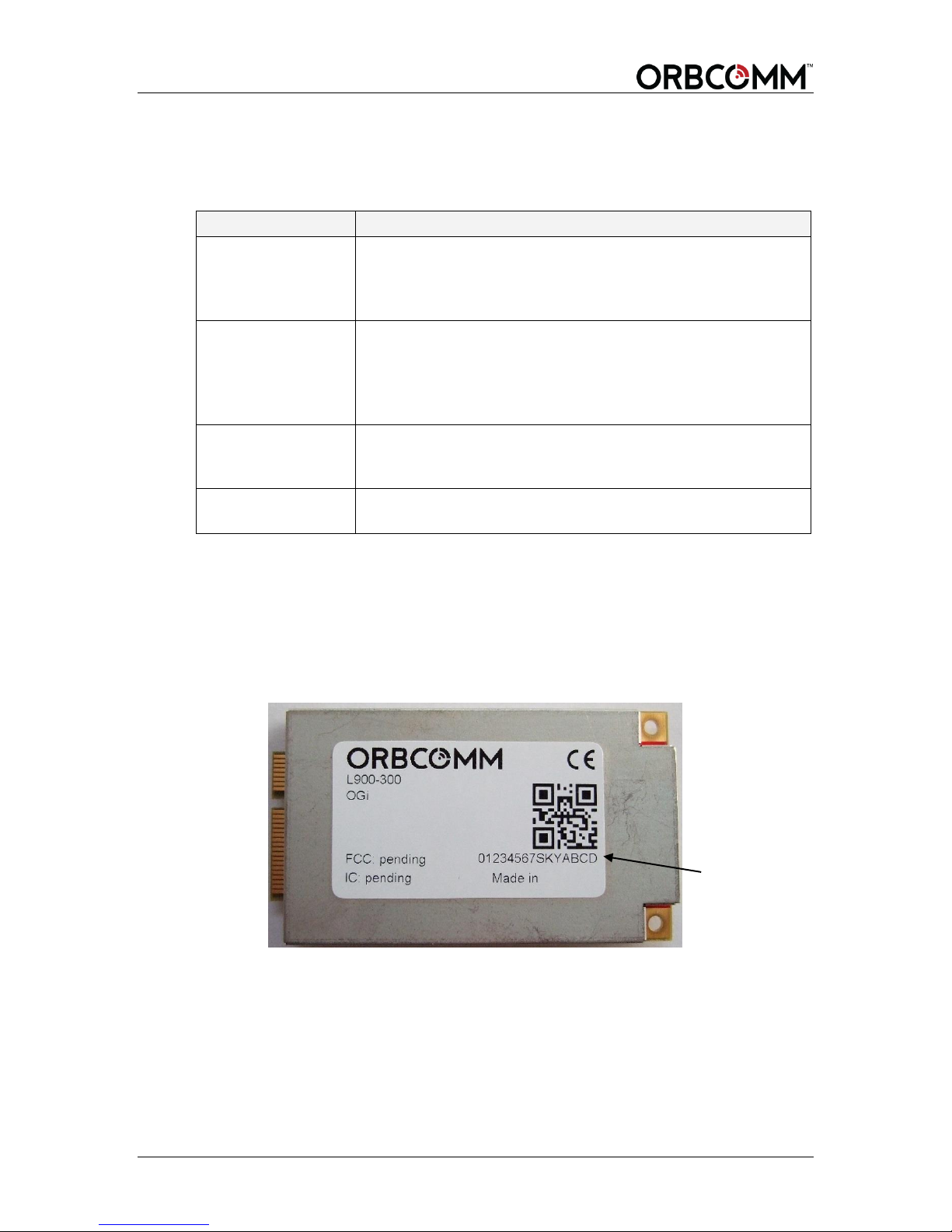
Each modem has a mobile ID used to register it on the IsatData Pro network. The mobile
ID is a 15-digit alphanumeric identifier in the format NNNNNNNNSKYXXXX.
Figure 20 shows the location of label.
Figure 20 Mobile ID Location
T401, Version .15 28 © ORBCOMM Proprietary
Page 29

OGi Modem - Hardware Guide
4 Integration Guidelines
This section contains a number of guidelines to assist the OEM Integrator in building
their enclosure. It must be recognized that this section provides guidelines only and each
OEM Integrator must use their own discretion to finish the integration approach that
works for them.
4.1 Regulatory Guidelines
The OEM Integrator must recognize the importance of regulatory requirements for their
integrated design. These requirements can have a major impact on the product design
functioning and schedule. Further, as the regulatory requirements can be quite complex,
ORBCOMM recommends that OEM Integrators always seek the advice of a regulatory
expert prior to starting integration. This advice allows the OEM Integrator to properly
plan and schedule design and test requirements.
When the regulatory tests are defined, it is also important to identify authorized test labs
that are qualified to perform the required tests. Prior to a design, critical tests should be
identified. It is recommended that the OEM Integrator pretest any high risk critical
specifications early in the design stage.
4.2 Compliance
Refer to section 2 for compliance information.
4.2.1 Reference Power Supply
The internal power supply operates between 5.0 and 15.0 VDC. A full RF output requires
an input voltage above the minimum operating voltage.
4.2.2 Review Process
The OGi modem integration can be challenging as the modem is a sensitive receiver that
has stringent emission specifications.
To help minimize integration risk, ORBCOMM recommends that the OEM Integrator
consult with ORBCOMM and review the mechanical integration prior to starting a
detailed design.
4.3 EMI/EMC Guidelines
The modem and antenna form a highly sensitive receiver that can receive very weak
satellite or GNSS signals. The highly sensitive receiver can also pick up noise or other
interference. Components such as processors and support circuitry should be shielded
with good quality shielding. It is also recommended that RF coupling/bypass capacitors
be added to the power supply rail, as close as possible to the modem's power pin. Digital
interface devices should be shielded, and care must be taken to ensure the digital
interface cable does not run close to the antenna.
© ORBCOMM Proprietary 29 T401, Version .15
Page 30
OGi Modem - Hardware Guide
Application
Cable Type
Connector
Max. Total
Loss at
1.6 GHz
Cable
Example
Packaged/Remote
Antenna cable
RF Coaxial
50 Ω
MMCX male/SMA
male
1.5 dB
LMR195
Unpackaged
Antenna Cable
RF Coaxial
50 Ω
MMCX male/IPEX
plug male
0.5 dB
-
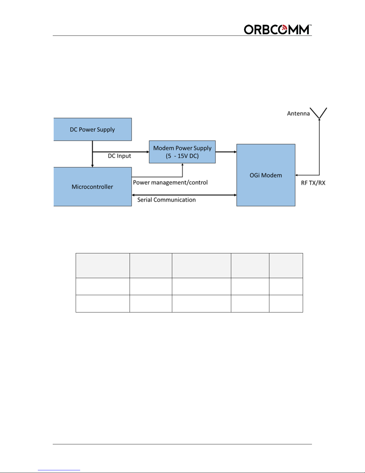
4.3.1 Typical Integration
The modem is intended to be used in a larger system. The system must provide adequate
power (low noise and relatively high current) and must possess an electrical signaling
mechanism compatible with the modem. Ensure that the custom designed circuit board
does not create undesirable signals that can impact the performance of the modem. An
external antenna is required to complete the modem design.
Figure 21 Typical OEM Integrator Modem Design
4.3.2 Antenna Cable Guidelines
The OEM Integrator is responsible for designing a custom-made RF cable to connect
antenna and modem. The following recommendations provide some guidelines for RF
cable selection:
4.3.2.1 General Guidelines for Antenna Positioning
Antenna placement is important. When positioning the antenna consider EMI
performance of the integration product and visibility to the sky.
Depending on the EMI performance of the integration product, the satellite antenna may
need to be paced a distance away from the integration product.
The antenna must be positioned such that it has a good view of the sky and there is no
metal/circuit board nearby to interfere with or block the antenna.
4.3.3 Host Shielding
In a typical integration, the modem is controlled by microcontroller.
The microcontroller and supporting circuitry, such as memory, high speed data/address
bus, clock references and power supply sources are normally noisy and could potentially
T401, Version .15 30 © ORBCOMM Proprietary
Page 31

OGi Modem - Hardware Guide
5
affect the highly sensitive satellite or GPS receiver performance if the antenna is placed
too close to the circuitry.
The following guidelines are provided when building a microcontroller using the modem.
Microcontroller and circuitry should be fully shielded.
Digital interfaces such as serial ports, USBs and I2C along with their tracks
should be shielded.
Avoid running any digital interface connector and cable close to the antenna. Do
not route any metal or cable above the ground plane of the antenna card or above
the antenna.
4.3.4 Decoupling
The following are recommendations for the power supply and digital lines to reduce
emissions that could be picked up by the modem.
RF decoupling/bypass capacitors (22pF 0403 or 33pF 0603 typical) be added as
close as possible to the modem's power pin on the power supply rail of the
processor and high speed digital circuitry.
RF decoupling/bypass capacitors added on the interface power rails.
4.4 Maximum Current
It is recommended that the power supply be designed with a margin to supply the
maximum current required by the modem. Refer to sections 3.4.1 and 3.4.2 for maximum
current and inrush current requirements when designing a power supply.
4.5 Enclosure Design
The modem is not designed for outdoor environments. Consequently, the enclosure
typically requires a robust environmentally sealed enclosure that can house the modem.
The following guidelines are recommended for the enclosure design.
An IP67 rating5 or better for outdoor use.
Use enclosure materials that are transparent to L-Band (1-2 GHz) radio signals.
Lexan Resin EXL 9330 is a common recommended enclosure material, but there are
many other suitable materials.
The unpackaged standard antenna is supplied with a dielectric cap, a piece of plastic
over the ceramic patch antenna that helps to negate the effects of different enclosure
materials on the performance of the antenna. With the dielectric cap, the standard
unpackaged antenna can be placed as close as desired to the adjacent enclosure
material.
The unpackaged low elevation antenna is less sensitive to enclosure material
selection and does not require a dielectric cap.
IEC 60529
© ORBCOMM Proprietary 31 T401, Version .15
Page 32
OGi Modem - Hardware Guide
Screw holes (2)
Mate with
a Mini PCI
Express
Connector
Do not use metallic paint or tinting that may be conductive.
4.5.1 Label Guidelines
The label on the modem includes its mobile ID. If the modem is placed inside of an
enclosure that is not intended to be opened, an exterior label must be affixed to the
enclosure, in a visible location.
When integrating the modem into an enclosure, you must do one of the following:
Provide visibility of the modem through a window.
Provide an easy way to get to the modem when an access panel or door is
removed.
Place a label on the outside of the final enclosure that contains the following
information:
A copy of the ORBCOMM logo
Text that indicates the enclosure contains a transmitter
The mobile ID
A list of all valid certifications (for example, ETSI, Industry Canada, etc.)
With this information on the enclosure, installers can readily identify the required
information.
4.5.2 Mating Connector Guidelines
Refer to section 3.1 for connector guidelines.
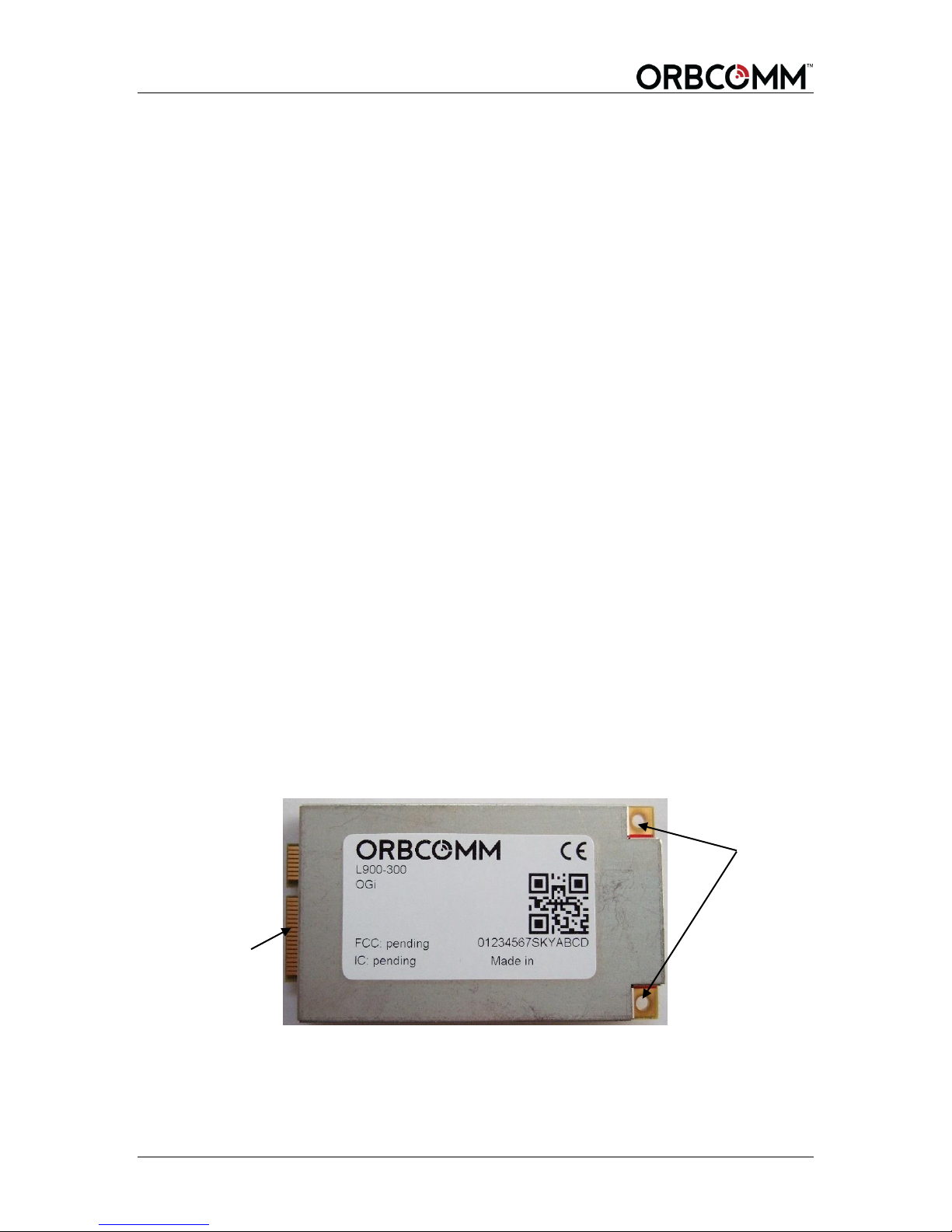
4.6 Modem Mounting Guidelines
As shown in Figure 22 the modem has a hole in each corner of the enclosure sized for
M2.5 hardware to secure the modem to an application card or other environmental
enclosure surface.
Figure 22 Modem Mounting Holes
T401, Version .15 32 © ORBCOMM Proprietary
Page 33
OGi Modem - Hardware Guide
MMCX
Connector
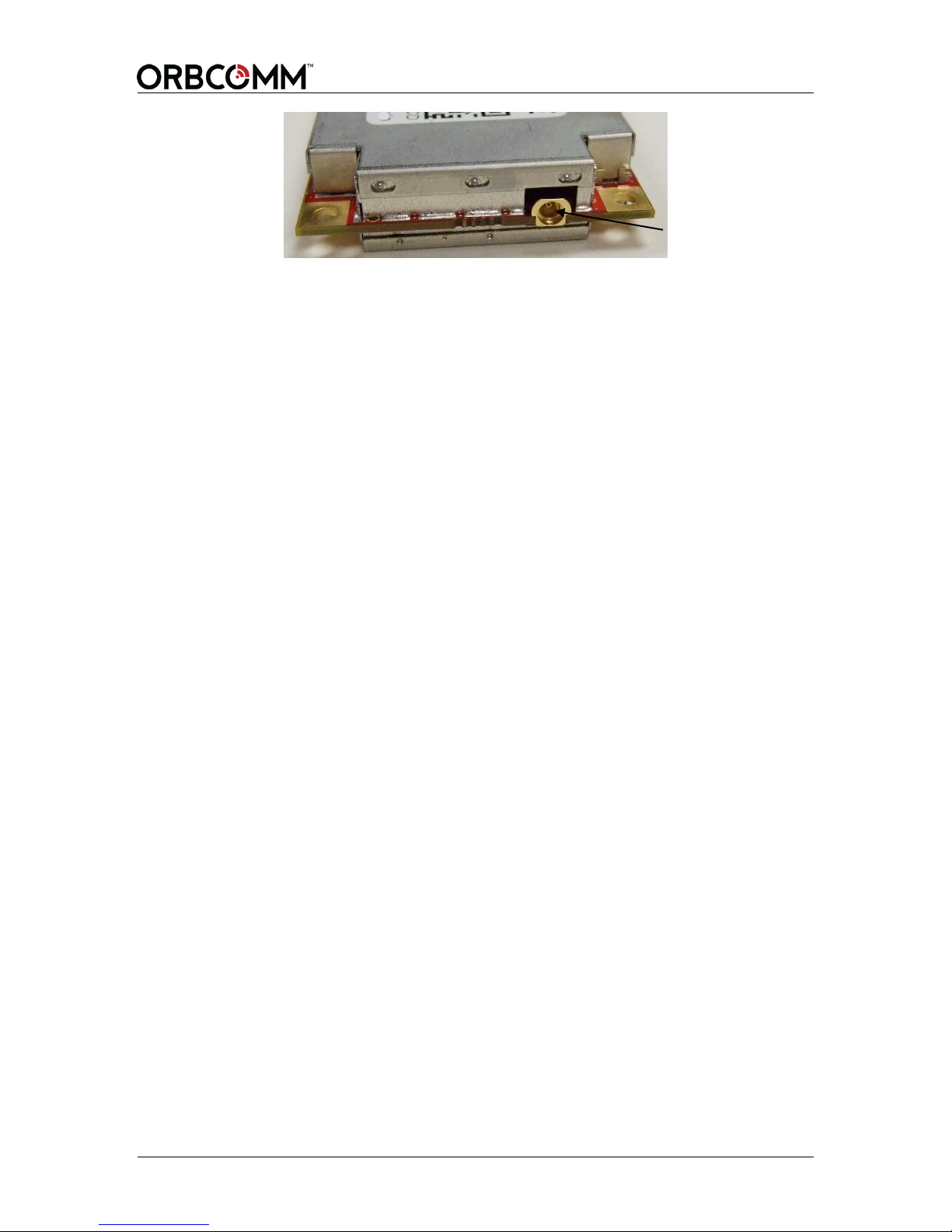
The modem inserts into the connector at an angle, and is held in place with screws and
standoffs that match the connector height. The standoffs and screws generally interface to
a ground connection on the host board. Mounting screws should be properly tightened to
0.80 N-m (7 pound-inches) of torque or as per the specifications of the connector
Manufacturer.
4.7 Unpackaged Antenna Mounting Guidelines
As shown in Figure 17 the unpackaged antenna has a set of four holes sized for M3.5
hardware to secure the antenna to an environmental enclosure surface. A second set of
holes at the corner of the card can be used for mounting with #4 hardware, but the holes
are tight fitting and tolerances need to be considered, so SkyWave recommends the larger
hole set for mounting.
© ORBCOMM Proprietary 33 T401, Version .15
Page 34
OGi Modem - Hardware Guide
5 Antenna Installation
The following section contains ORBCOMM's recommended installation guidelines for
installing the antenna. It is recommended that the OEM Integrator include these in the
installation guidelines for end users.
5.1 Antenna Mounting Guidelines
CAUTION Mount the antenna at
least 20 cm away from humans.
The following guidelines for mounting the remote antenna also apply to an OEM Product
that includes the unpackaged antenna where applicable.
For fixed installations ensure that the antenna is pointing toward the equator,
facing south if in the Northern Hemisphere and facing north if in the Southern
Hemisphere, and its line of sight to the sky (satellite) is clear of obstructions.
For a mobile installation, mount the antenna at the highest point on the vehicle or
vessel where it has a clear view of the sky (satellite) in all directions.
Do not mount the antenna near metal objects. The antenna can communicate with
the satellite through fiberglass, but not through metal. Metal causes interference
if it is above the antenna and within 10.2 cm from the top of the antenna. Respect
the 20° or -15° elevation angle requirement with metallic object. Ensure that the
antenna is at least 1.3 cm higher than the metallic surface in cases where it must
be mounted next to a vertical metallic surface.
Ensure that any paint above the antenna is non-metallic and non-metallic flake, if
the installation is under fiberglass or composite wind fairings.
Mount the antenna on a surface that does not exceed the antenna's maximum
operating temperature. Locating the antenna where temperatures exceed the
recommended range might compromise performance.
Do not mount the antenna close to an exhaust pipe due to the excessive heat and
the potential for the exhaust pipe causing satellite blockage.
Do not mount the antenna close to air horns or any tractor roof hardware
(for example, emergency lights) that could interfere with satellite
communications.
Mount the antenna on the driver's side of the vehicle, if possible, when there is a
possibility of strikes by overhanging tree branches.
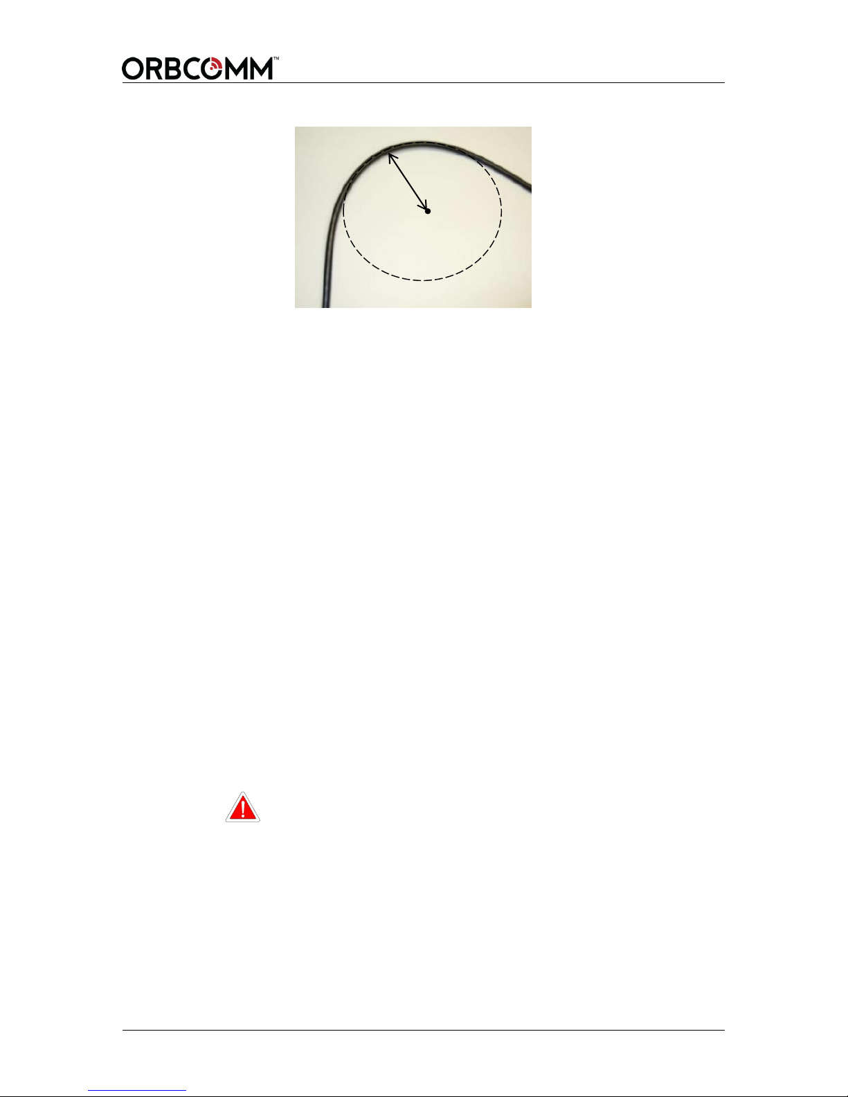
Do not drill any holes before checking that you have room for the bend radius of
the low loss coax cable. For reliable operation, do not go below a bend radius of
1.3 cm. Measure the bend radius of the cable as shown in Figure 23.
T401, Version .15 34 © ORBCOMM Proprietary
Page 35
OGi Modem - Hardware Guide
Radius
Correct
(Minimum
Figure 23 Antenna Cable Bend Radius
Bend
1.3 cm)
Mount on a surface that is free from dirt, grime, water and grease to avoid
damaging the mounting surface or the vehicle’s paint.
Mount so that the cable end faces the rear of the vehicle.
5.2 Mount a Remote Antenna
Two mounting options are available for the remote packaged satellite antennas: screw
mount or silicone mount. OEM Integrators, who have included an unpackaged antenna
within their product, should apply any packaged antenna restrictions mentioned in this
section, to the mounting of their own product.
5.2.1 Screw Mount
If mounting a remote antenna the following tools and materials are required:
Drill
M4 hardware
Outdoor waterproof adhesive sealant (silicone)
To mount the antenna, follow the steps below.
1. Find a location for the remote antenna following the guidelines provided in
Section 5.1.
2. Use the mounting template (APPENDIX A) or the antenna as a template, to mark the
location of the mounting holes.
CAUTION Cable management and connector strain relief MUST be
3. Drill the mounting holes using the drill.
incorporated in the installation. Secure the cable no more
than 15 cm from the antenna enclosure and at regular
intervals along its length as part of the installation to prevent
cable wear and eliminate strain on the terminal connector.
Damage to the terminal connector interface or cable might
otherwise result leading to hardware failure.
4. Apply waterproof sealing compound, such as RTV silicone, around the drill holes so
water does not seep into the asset.
© ORBCOMM Proprietary 35 T401, Version .15
Page 36
OGi Modem - Hardware Guide
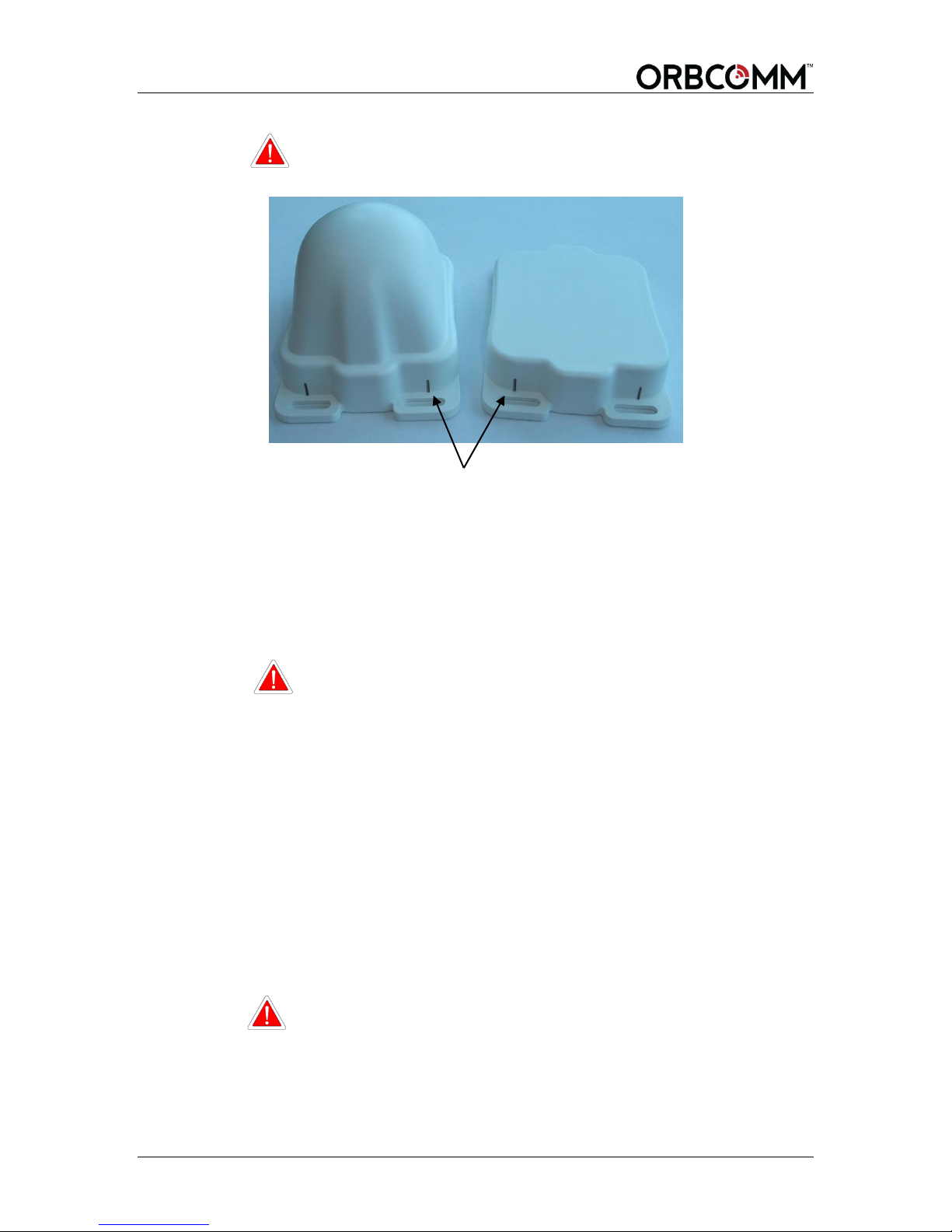
Do Not Block These Features
CAUTION Adhesive or silicone cannot block the air vent features shown
5. Secure the antenna in place with self-tapping screws or machine screws and nuts
depending on access to the mounting surface. The remote antenna might also be
mounted using adhesive or a high strength outdoor grade silicone when mounting
holes are not an option in the mounting surface.
in Figure 24.
Figure 24 Air Vent Feature
Note: The recommended torque specification is approximately finger tight plus a
45 degree rotation using an 8 mm wrench.
CAUTION Cable management and connector strain relief MUST be
5.2.2 Adhesive Mount
The remote antenna might also be mounted using adhesive or a high strength outdoor
grade silicone when mounting holes are not an option in the mounting surface.
Refer to the adhesive manufacturer's recommendations for application temperature,
application conditions, compatible bonding materials, and minimum curing times when
working with an adhesive. Failure to follow the manufacturer's guidelines could result in
the remote antenna separating from the mounting surface.
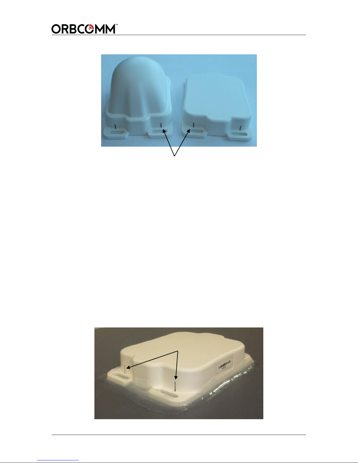
CAUTION Adhesive or silicone cannot block the air vent features shown
incorporated in the installation. Secure the cable no more
than 15 cm from the enclosure and at regular intervals along
its length as part of the installation to prevent cable wear and
eliminate strain on the terminal connector. Damage to the
connector interface or cable might otherwise result leading to
hardware failure.
in Figure 25.
T401, Version .15 36 © ORBCOMM Proprietary
Page 37
OGi Modem - Hardware Guide
Do Not Block These Features
Do Not Block These Features
Figure 25 Air Vent Feature
5.2.2.1 Silicone Side Connector Mount
The following tools and materials are required if mounting a side cabled remote antenna
with silicone.
Outdoor rated silicone adhesive sealant (GE RTV 108)
Isopropyl alcohol or an equivalent
To mount the antenna:
1. Find a location for the remote antenna following the guidelines provided in
Section 5.1.
2. Clean the asset surface with isopropyl alcohol or an equivalent product that does
not leave a residue.
3. Apply silicone around the hole in the asset and to the bottom surface of the
remote antenna and position onto the assets surface.
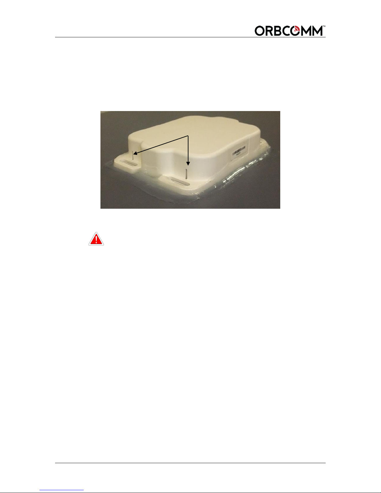
4. Apply a generous bead of silicone around the entire perimeter of the remote
antenna enclosure. The two vertical slots shown in Figure 26 are vent features
and must not be filled with silicone.
Figure 26 Apply Silicone to Remote Antenna
© ORBCOMM Proprietary 37 T401, Version .15
Page 38
OGi Modem - Hardware Guide
5. Place some weight on the remote antenna while the silicone cures.
CAUTION Cable management and connector strain relief MUST be
incorporated in the installation. Secure the cable no more than
15 cm from the antenna enclosure and at regular intervals along
its length as part of the installation to prevent cable wear and
eliminate strain on the terminal connector. Damage to the
terminal connector interface or cable might otherwise result
leading to hardware failure.
5.2.2.2 Silicone Bottom Connector Mount
The following tools and materials are required if mounting a remote bottom connector
antenna with silicone.
Outdoor rated silicone adhesive sealant (GE RTV 108)
5/16” or 8 mm wrench
Drill
12 to 19 mm drill bit for a straight SMA cable connector
29 mm minimum drill bit (hole saw) for right angle SMA cable connector
Isopropyl alcohol or an equivalent
To mount the antenna:
1. Find a location for the remote antenna following the guidelines provided in
Section 5.1.
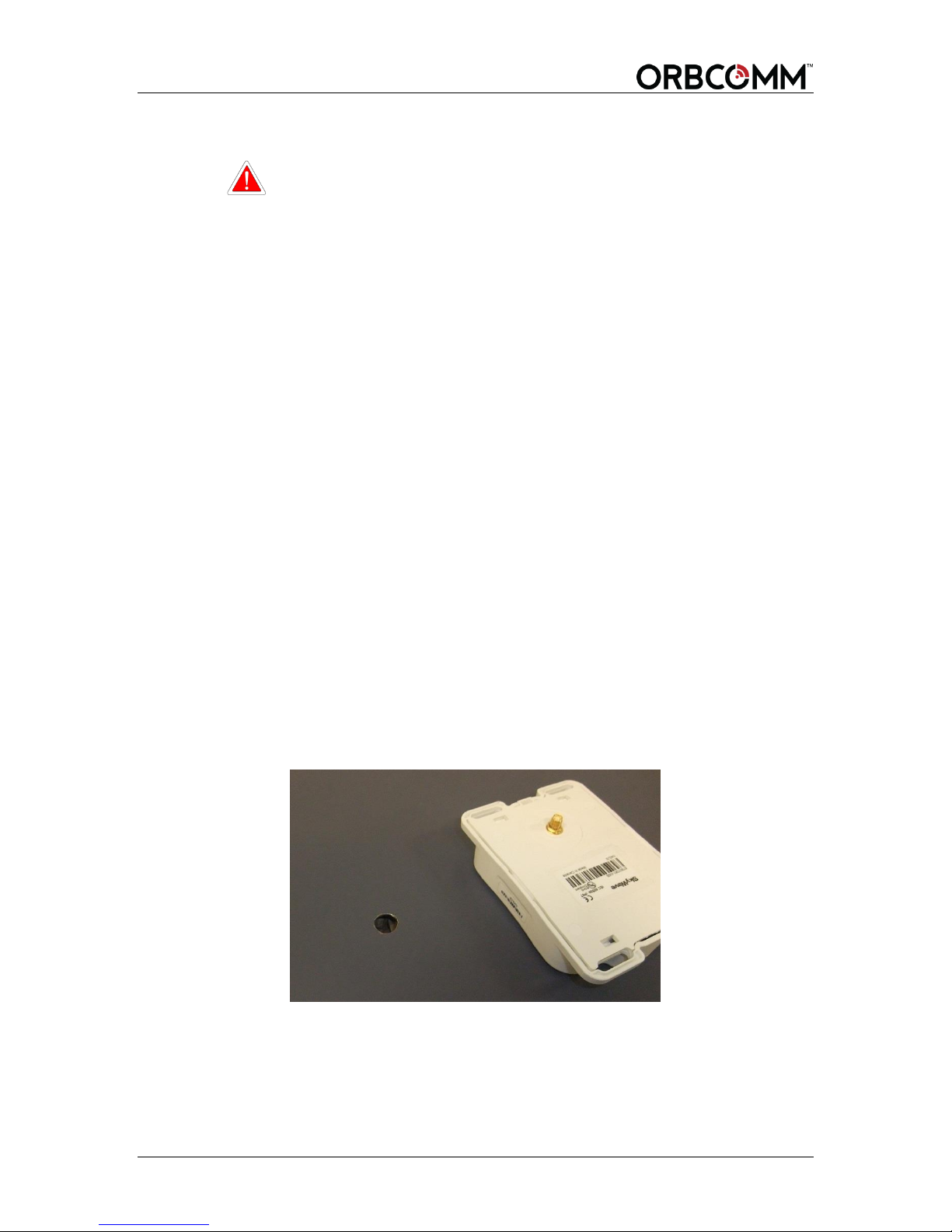
2. Drill a 12 to 19 mm hole in the asset surface (Figure 27) when using a straight
SMA cable connector. For a right angle SMA cable connector, drill a minimum
hole diameter of 29 mm.
Refer to the note in step 7 if the right angle hole is considered too large.
Figure 27 Drill Mounting Hole
3. Clean the asset surface with isopropyl alcohol or an equivalent product that does
not leave a residue.
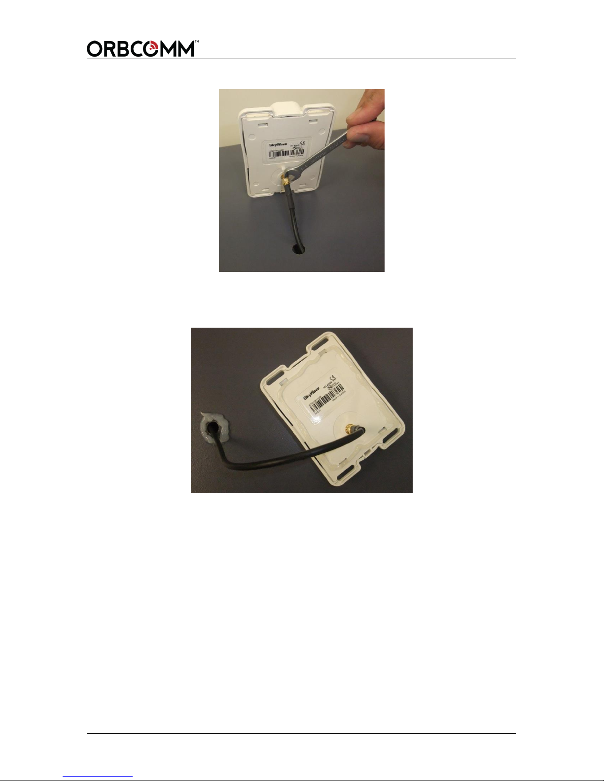
4. Insert the cable through the hole, from inside the asset, and thread the cable
connector onto the antenna. Torque the connector finger tight plus a 45 degree
rotation using an 8 mm wrench.
T401, Version .15 38 © ORBCOMM Proprietary
Page 39
OGi Modem - Hardware Guide
Figure 28 Attach Cable to Antenna
5. Apply silicone around the hole in the asset and to the bottom surface of the
remote antenna.
Figure 29 Apply Silicone to Hole in Asset
6. Lower the remote antenna onto the mounting surface.
The straight SMA cable connector can be lowered straight down onto the
mounting surface.
The right angle SMA cable connector, not shown, must be pivoted down onto the
mounting surface to fit the right angle cable and connector through a larger
clearance hole. Additional care is required with this installation to ensure the
right angle cable and connector does not smear the silicone around the clearance
hole when attempting to pivot the antenna into position.
7. Apply a generous bead of silicone around the entire perimeter of the remote
antenna enclosure. The two vertical slots shown in Figure 26 are vent features
and must not be filled with silicone.
Note: If the large clearance hole required for the right angle SMA cable
connector is considered too large, you have the option to use a smaller
clearance hole in the mounting surface and install the cable from
inside the asset after the antenna has been adhered with silicone.
© ORBCOMM Proprietary 39 T401, Version .15
Page 40
OGi Modem - Hardware Guide
Do Not Block These Features
In this case, first confirm there is enough room from inside the asset to
thread the SMA cable connector by hand and clearance for the wrench
to apply the final torque.
Also note that the silicone used to mount the antenna must be fully
cured before the cable can be installed from the inside otherwise the
seal and mounting are compromised.
8. Place some weight on the remote antenna while the silicone cures.
Figure 30 Apply Silicone to Terminal
CAUTION Cable management and connector strain relief MUST be
incorporated in the installation. Secure the cable no more than
15 cm from the antenna enclosure and at regular intervals along
its length as part of the installation to prevent cable wear and
eliminate strain on the terminal connector. Damage to the
terminal connector interface or cable might otherwise result
leading to hardware failure.
T401, Version .15 40 © ORBCOMM Proprietary
Page 41
OGi Modem - Hardware Guide
Description
Part Number
OGi modem with embedded antenna
L900-300
OGi modem with remote standard antenna
L900-301
Packaged Antennas
Part Number
Standard (side mount SMA connector, no cable)
ST100368-NSA
Standard (bottom mount SMA connector, no cable)
ST100368-NSB
Low Elevation (side mount SMA connector, no cable)
ST100369-NSA
Low Elevation (bottom mount SMA connector, no cable)
ST100369-NSB
Unpackaged Antennas
Part Number
Standard (passive antenna)
ST100425-001
Low Elevation (passive antenna)
ST100426-001
Contact your Account Executive for additional products and ordering codes
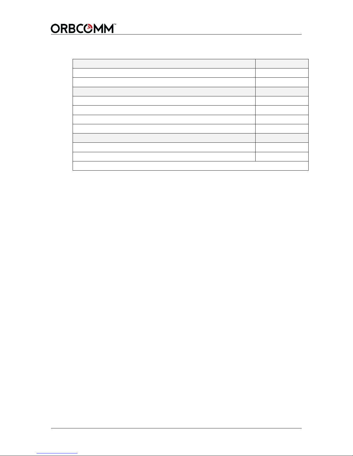
APPENDIX A Order Part Numbers
© ORBCOMM Proprietary 41 T401, Version .15
Page 42
OGi Modem - Hardware Guide
126.2±0.2
2 x 112.8
4 x 15.9
35.5±0.2
46.5±0.2
4 x 5.500
(HOLE)
2 x 72.4
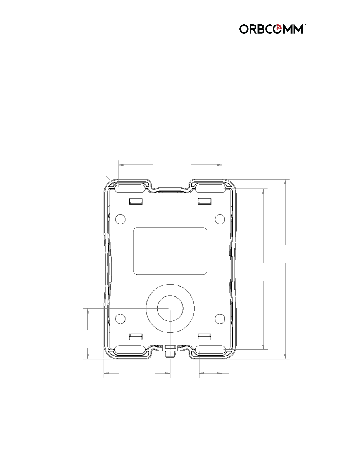
APPENDIX B Remote Antenna Template
CAUTION Before drilling check the template against actual hardware for
dimensional accuracy. If it is not correct, DO NOT USE THIS
TEMPLATE.
CAUTION Cable management and connector strain relief MUST be
incorporated in the installation. Secure the cable no more than
15 cm from the antenna enclosure and at regular intervals along
its length as part of the installation to prevent cable wear and
eliminate strain on the connector. Damage to the connector
interface or cable may otherwise result leading to hardware
failure.
T401, Version .15 42 © ORBCOMM Proprietary
Page 43

OGi Modem - Hardware Guide
CFR
Code of Federal Regulations
DC
direct current
FCC
Federal Communications Commission
GND
ground
GPS
Global Positioning System. A satellite-based system that allows the modem
to determine the longitude and latitude (and hence the location) of a
monitored mobile device.
I/O
input/output
IC
Industry Canada
IEC
International Electrotechnical Commission
N-m
Newton-Meters
PCB
printed circuit board
PPS
pulse per second
R&TTE
Radio and Telecommunications Terminal Equipment
RF
radio frequency
RoHS
Restriction of Hazardous Substances
Rx
receive
Tx
transmit
UART
Universal Asynchronous Receiver/Transmitter
Acronyms/Glossary
© ORBCOMM Proprietary 43 T401, Version .15
Page 44
OGi Modem - Hardware Guide
Version
Date
Details
.15
Jan 2016
Limited customer release
.13
Jan 2016
Limited customer release
.02
Aug 2015
Limited customer release
Revision History
T401, Version .15 44 © ORBCOMM Proprietary
 Loading...