

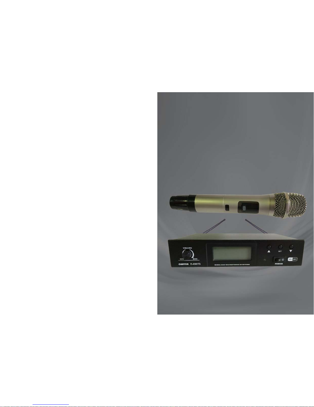
ORATOR AUDIO
D690D/D690TD
WIRELESS MICROPHONE
SYSTEMS
INSTRUCTION
MANUAL

CONTENTS
For technical assistance or service enquiries,
please contact ORA TOR AUDIO on:
02.9938 6866
enquiries@orator-audio.com
Description Page Number
Introduction 1
System Components 2
Control Panels 3-4
System Set Up 5
Frequency Setting 6
Trouble Shooting 7
T echnical Data 8

Transmitter (hand-held):
RF generation/controI PLL
Frequency range UHF 520 - 694 MHz.
Switching bandwidth Max. 32 MHz
Channel grid 100 kHz
RF power output 30mW
Nominal/peak deviation +24k Hz / +/- 45 kHz
Current loss 140mA
Use range D690D: Max 100m (80m ideal)
D690TD: Max 300m (200m ideal)
Pickup Dynamic
Battery AA (1.5V) x 2
Power Life 8 - 10 hours
Receiver :
Sensitivity 1 uV (sinad = 12 dB)
Switching bandwidth Max. 32 MHz
Receiving frequencies 100
Channel spacing > 400 kHz
Spurious rejection 80 dB
Image rejection 80 dB
Signal/Noise ratio 90 dB
AF output 0 - 300 mV
Receiving channel One channel
Power DC 13 - 18 V
Power consumption 5W
Size 210 x 180 x 45 mm
Weight 800 g
Introduction:
Your D690 series system has been designed to suit the Australian
Government’s new laws relating to Wireless Microphones that came into
effect on January 1, 2015. The laws limit the approved UHF frequency
range to 520 - 694 MHz. The available UHF frequency in Australia has
been significantly reduced in bandwidth, and coupled with the types of
other technology that use this frequency band, notably TV broadcast, there
is now greater potential for frequency interference. For this reason, the
D690 series has been been developed with 100 selectable frequencies
available, so you can choose an alternative “clean” frequency if necessary .
The frequency that TV stations use does vary by area throughout
Australia, so problem interference frequencies tend to be area specific.
Once you find a suitable frequency for your area, you should find that the
frequency does not need regular changing unless you move around
Australia.
There are 2 models, both single channel (1 microphone only), available in
the series:
D690D is a Diversity system for normal use, with an operating
distance of up to 100m (depending on local conditions),
D690TD is a True Diversity system for professional use, with an
operating distance of up to 300m (depending on local
conditions). Wikipedia describes True Diversity as:
“The professional models transmit in VHF or UHF radio frequency and have ‘true’
diversity reception (two separate receiver modules, each with its own antenna),
which eliminates dead spots (caused by phase cancellation) and the effects
caused by the reflection of the radio waves on walls and surfaces in general.”
The whole system circuitry is controlled by a microcomputer chip, and
you can choose the frequency to be used. The frequencies are displayed
on the Receiver screen & Transmitter, allowing for convenient control of
the system. The system uses a PLL synthesiser to generate the
frequency and ensure better frequency stability , and enable the user to
easily choose a frequency without any interference caused by the local
environment. The Transmitter (hand microphone or beltpack) is
synchronised with the Receiver using infrared technology.
Technical Data:
--- 1 ---
--- 8 ---
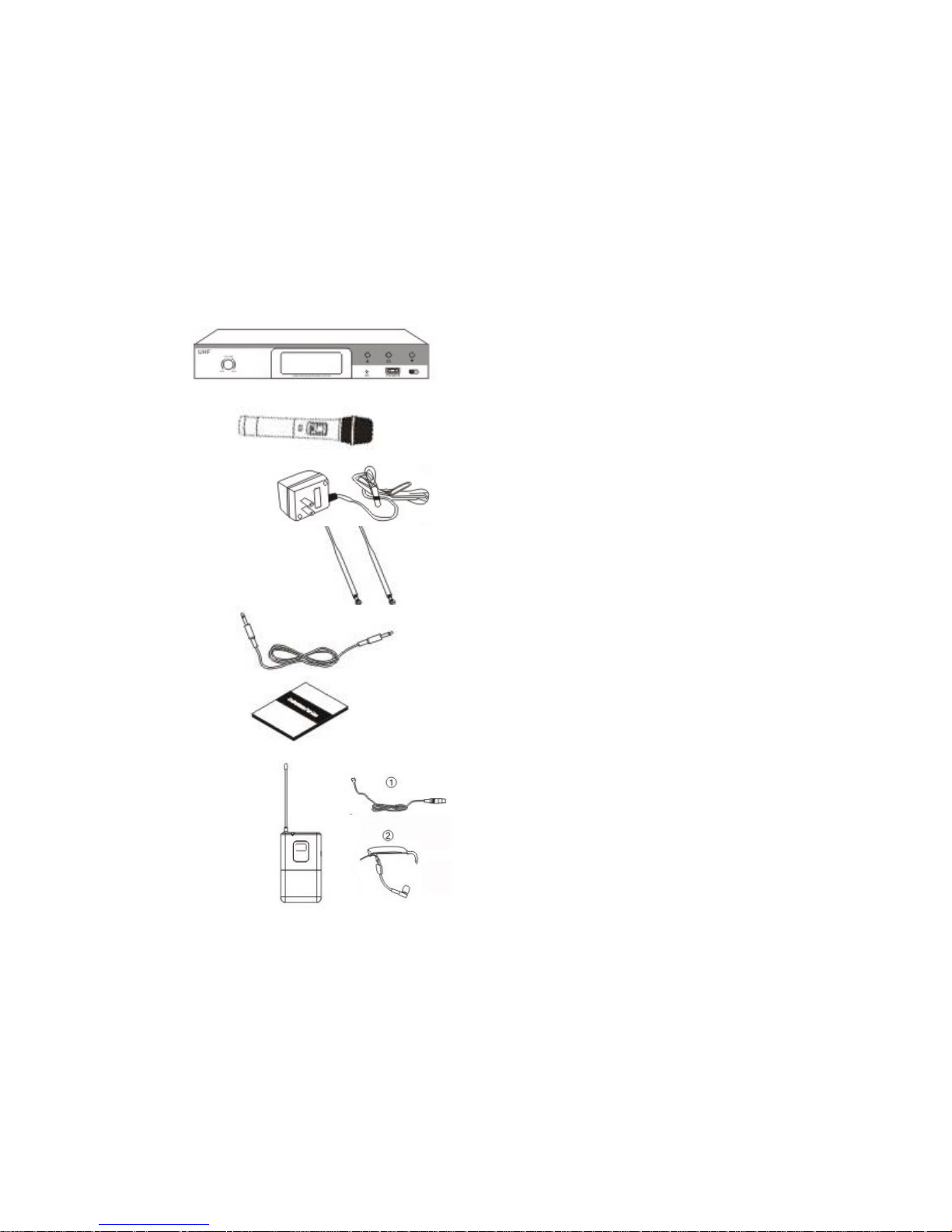
System Components:
1. Receiver
2. Hand held Microphone
incl batteries
3. DC Power Adapter
4. Receiver Aerial (2 for D690TD)
5. Microphone cable with
6.3mm (1/4”) connectors
6. Instruction Manual
and if ordered,
7. Optional Beltpack Transmitter
with Headset & Lapel Microphones,
incl batteries
Troubleshooting:
1 .The Receiver is turned on but the indicator light is not lit?
Make sure if the DC power cable is properly fiitted into the power
socket & the DC cable is firmly fitted into the Receiver.
2. When you turn on both the Receiver & Transmitter (Microphone or
Beltpack), the RF light does not come on.
The RF light should come on when both transmitter & receiver are
on & the frequencies are matched. Check the power indicator light is
on in the Receiver & the Transmitter is not showing “Low Battery”. If
OK, then check that the frequency is matched & reset if necessary.
3. When you speak into the Microphone, no sound is heard from the
Amplifier/Speaker.
Make sure the volume on the Receiver is turned up, and check that
the audio (6.3mm) cable is properly installed.
4 .The audio output signal is not very good.
Check that you have installed the antennae.
Check that the Transmitter battery is not too low..
Check that the Receiver is within range & not obstructed by too
many solid objects.
Perhaps there is a strong interference in your area & you need to
change frequency.
5. The quality of the sound is not good.
Check that the Transmitter battery is not too low..
Perhaps there is a strong interference in your area & you need to
change frequency.
--- 2 ---
--- 7 ---

System Controls:
1. Receiver:
FRONT P ANEL:
REAR PANEL:
1 : Power Switch
2 : UP button (frequency selection)
3 : Down button (frequency selection)
4 : IR button
5 : LCD Display
6: Volume adjustment.
7: IR LED Receiver
8 : Unbalanced Output Connector (6.3mm cable included)
9 : Balanced Output Connector
10. DC power socket
11. Receiver Antenna
System Set Up:
2. Frequency Setting:
Your system comes with the hand held microphone already set to match
the existing frequency of the Receiver. To get a suitable frequency for your
area, a simple “trial and error” approach is usually the fastest solution.
Simply follow the operating instructions to test the signal quality of the
existing frequency set in the system. If you do suffer some interference,
then follow the instructions below to change your frequency.
A. Press UP button or Down button to choose lhe working frequency and press IR
Button to confirm.
B. Turn on the Power of the Microphone or Beltpack, put its infrared receiver
towards the infrared Transmitter LED of the Receiver and then press IR Button
on the Receiver. This will match the frequency of the Microphone or Beltpack to
the Receiver. When tho setting is completed, the receiver will exit the IR
transmitting mode.
C. Note that the IR receiver of the Beltpack is in the battery compartment area, so
the compartment door must be opened for the IR receiver to receiver the signal
from the Receiver unit. .
D. Y our system frequency should now be set (matched) and your system ready to
use.
--- 3 ---
--- 6 ---

System Controls:
2. Hand Held Microphone:
3. Beltpack Transmitter:
1: Microphone head protector
2: Display panel
3: Power on/off’ button
4: IR Receiver
5: Battery cover
1: Mi
2: Power on/off’ button
3: Transmitter Antenna
4: Low Voltage Light
5: Display
6: IR Receiver
7: Battery compartment
System Set Up:
1. Receiver Cable Connections:
The Receiver can be connected to an amplifier or mixer to process the
microphone signal. 2 outputs are provided:
1 balanced (XLR) socket and
2. an unbalanced (6.3mm ~ 1/4”) socket. A 6.3mm cable is included so
you can use this socket to connect your Receiver.
a. Connect the output to the mixer or amplifier input using the 6.3mm cable
provided, or using an XLR cable that you will need to source.
b. Connect the DC power adapter to the DC power socket on the rear
panel of the Receiver.
c. Attach the aerials provided to the Receiver .
Your system now just needs to be turned on & the system frequency set
(see next section) to be ready to use.
--- 4 ---
--- 5 ---
 Loading...