

Page 1

CISCO SMART GRID NETWORK
ENDPOINT USER MANUAL
2016
Page 2

Copyright 2016 by:
CORPORATE SYSTEMS ENGINEERING
Indianapolis, Indiana 46239
For Control When It Counts
1215 Brookville Way
Page 3

CORPORATE SYSTEMS ENGINEERING
Table of Contents
HARDWARE OVERVIEW .............................................................................................. 4
SPECIFICATIONS .......................................................................................................... 4
THEORY OF OPERATION ........................................................................................... 5
DATA MESSAGE FORMAT ............................................................................................ 6
COMMUNICATIONS BOARD ....................................................................................... 9
COMMUNICATIONS BOARD DIMENSIONS ............................................................ 10
Corporate Systems Engineering Proprietary and Confidential
CISCO USER MANUAL 3
D030416-01661V1-00 February 2016
Page 4

CORPORATE SYSTEMS ENGINEERING
POWER REQUIREMENTS
5 VDC / 2A
CURRENT DRAW
450Ma (Typ) 1A (Max)
MICROPROCESSOR
ARM Cortex-M3 with OTA Capabilities
RESET CIRCUITRY
External Microprocessor Supervisor
SERIAL INTERFACE BAUD
RATE
9600/N/8/1
SERIAL INTEFACE SIGNAL
LEVELS
3.3 VDC (TXD, RXD, GPIOs)
ANTENNA
Onboard antenna
OPERATING TEMP
-30 C to 70 C
FREQUENCY
902 TO 927 MHz
MESSAGE FORMAT
7BIT ASCII
MAXIMUM MESSAGE
LENGTH
460 CHACTERS
HARDWARE OVERVIEW
The primary purpose of this module is to allow Corporate Systems Engineering load control devices
and approved third party devices to communicate over a Cisco Mesh Network..
This is NOT intended to be instructional about how to design, develop, deploy or operate Cisco
Smart Grid Networks. Additionally, this should NOT be considered as a replacement for actual
Cisco education and training.
Should 3rd party require Engineering Support from CSE, it is considered external to this agreement.
SPECIFICATIONS
Corporate Systems Engineering Proprietary and Confidential
CISCO USER MANUAL 4
D030416-01661V1-00 February 2016
Page 5

CORPORATE SYSTEMS ENGINEERING
Channels
902.4 MHz to 927.6
MHz
64 Channels
Channel Spacing
400 KHz
Dwell Time per channel
400 ms
Window Per Channel
20 s
Maximum Occupied
Band Width
165 KHz
THEORY OF OPERATION
CSE COM module is based on Cisco Radio Frequency mesh technology and it communicates with
Neighborhood Area Network (NAN) rooted at a Cisco’s Connected Grid Router (CGR). CSE
COM module is driven by industry standards including UDP, IPV6, IEEE 802.15.4e, 802.1x /
EAP-TLS, and topology (Field Area Network with the Wide Area Network and Neighborhood Area
Network).
Mesh network can relay messages using routing technique. With routing, the message is propagated
along a path by hopping from node to node until it reaches its destination. To ensure all its paths'
availability, the network must allow for continuous connections and must reconfigure itself around
broken paths, using self-healing algorithms such as Shortest Path Bridging. Self-healing allows a
routing-based network to operate when a node breaks down or when a connection becomes
unreliable. As a result, the network is typically quite reliable, as there is often more than one path
between a source and a destination in the network. The channel hopping scheme employed in our
RF CG-Mesh networks is of Cisco's own design but based upon IEEE 802.15.4e.
CG-Mesh frequency hopping utilizes different channels randomly for transmission at different
times. Receiver will switch to the next channel for listening according to hash algorithm, and
transmitter has to learn the receiver’s schedule and use the same hash algorithm to calculate the
same channel index for transmission. Hence, the hopping is random.
Below is the list of frequency the module can utilize with a dwell time to send a packet that is no
greater than 400ms within 20s at each channel.
Corporate Systems Engineering Proprietary and Confidential
CISCO USER MANUAL 5
D030416-01661V1-00 February 2016
Page 6
CORPORATE SYSTEMS ENGINEERING
DATA MESSAGE FORMAT
The CSE CISCO communications module was developed by CSE to pass data to and from a
connected end devices via serial connection.
The message must be 7-bit ASCII characters.
ASCII characters below 0x20 (decimal 32, the Space character) and the DEL character
(0x7F) are not allowed. Invalid bytes are discarded.
The message must start with and open parenthesis “(“and end with a close parenthesis “)”.
The open and close parentheses characters are not allowed in the message data.
Messages total length must be from 2 to 460 characters.
Example message (U1291I0000017100EE000300033).
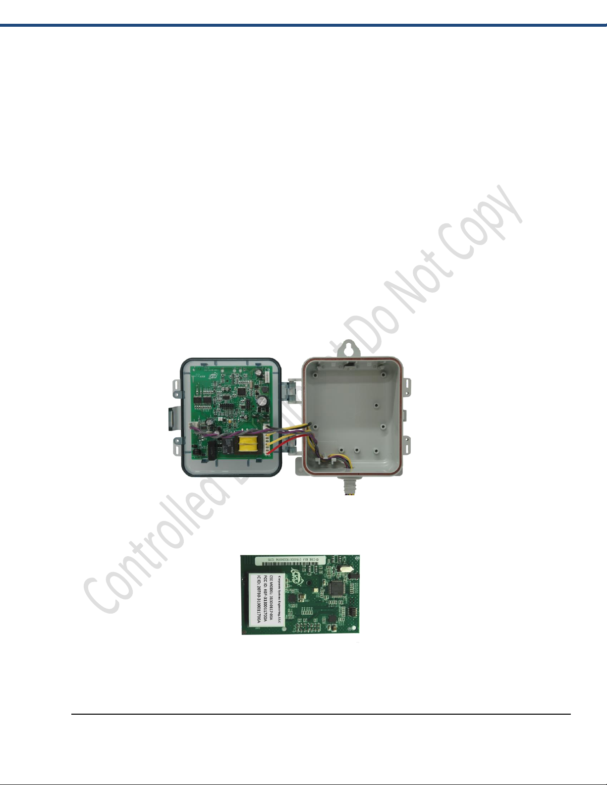
HOW TO INSTALL CSE CISCO MODULE INTO A CSE LOAD
CONTROL DEVICE
CSE Load Control Device
CSE Cisco Module Model 3130-0117-00A
Corporate Systems Engineering Proprietary and Confidential
CISCO USER MANUAL 6
D030416-01661V1-00 February 2016
Page 7
CORPORATE SYSTEMS ENGINEERING
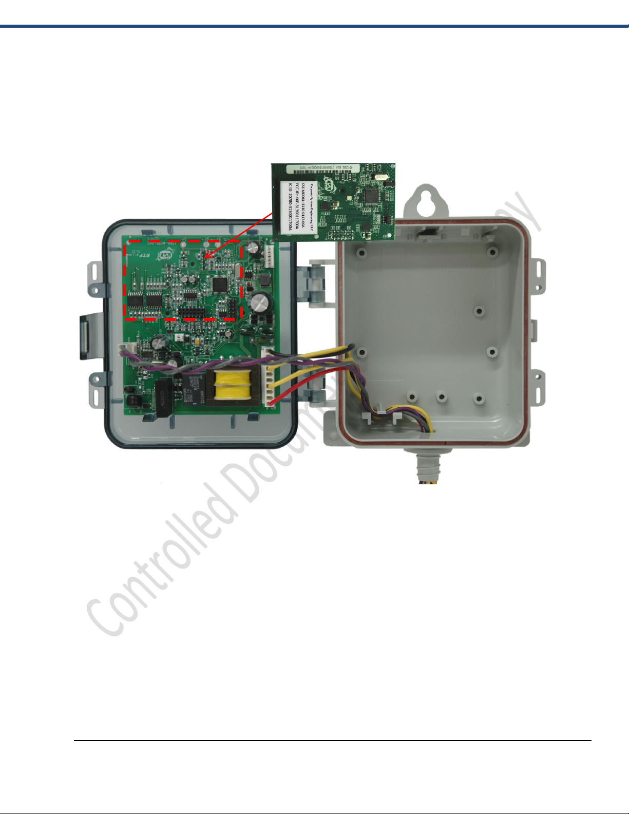
Install the Cisco Communication Module as shown in the following images below:
CSE Cisco Communication Module Placement
Corporate Systems Engineering Proprietary and Confidential
CISCO USER MANUAL 7
D030416-01661V1-00 February 2016
Page 8
CORPORATE SYSTEMS ENGINEERING
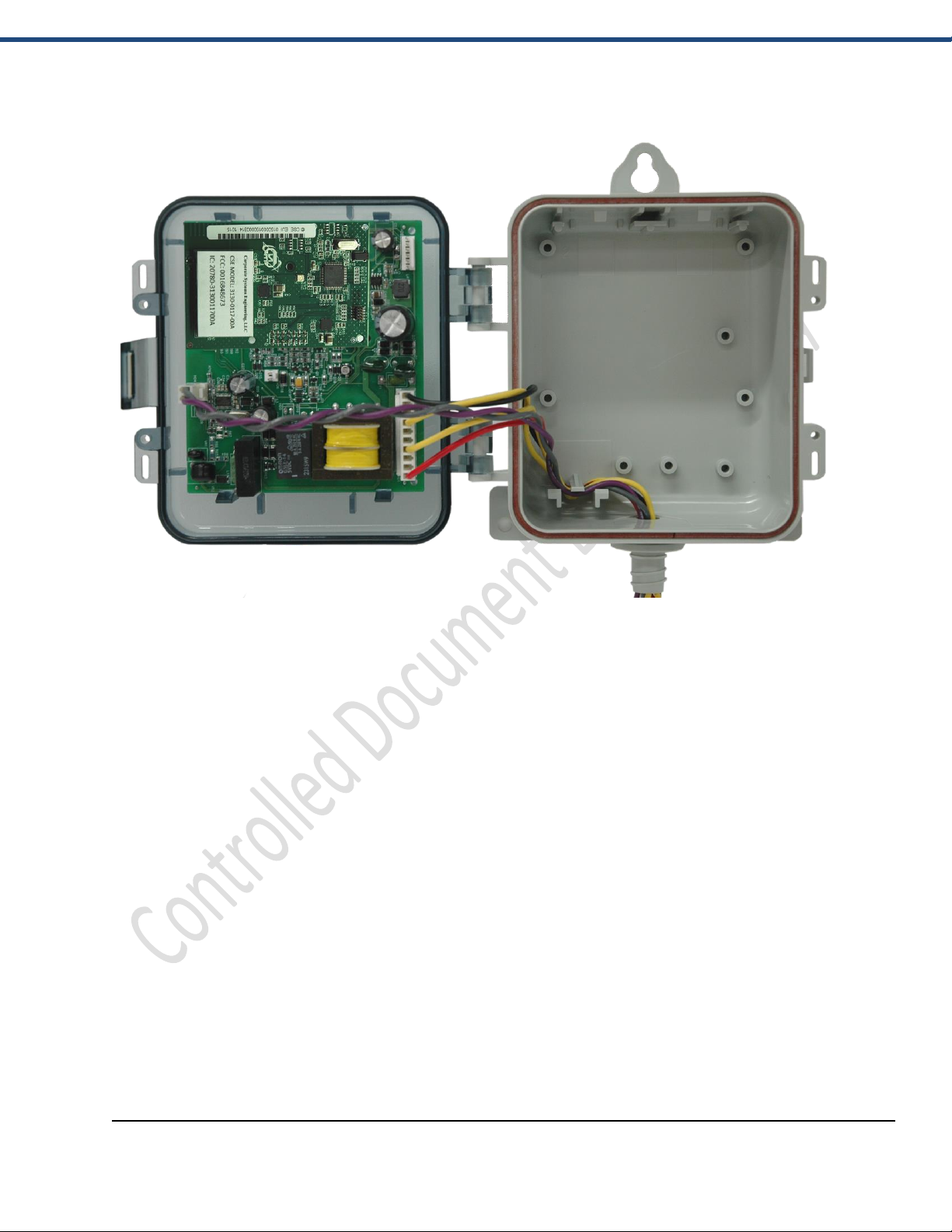
CSE Load Control Device with Installed Cisco Communication Module
Corporate Systems Engineering Proprietary and Confidential
CISCO USER MANUAL 8
D030416-01661V1-00 February 2016
Page 9
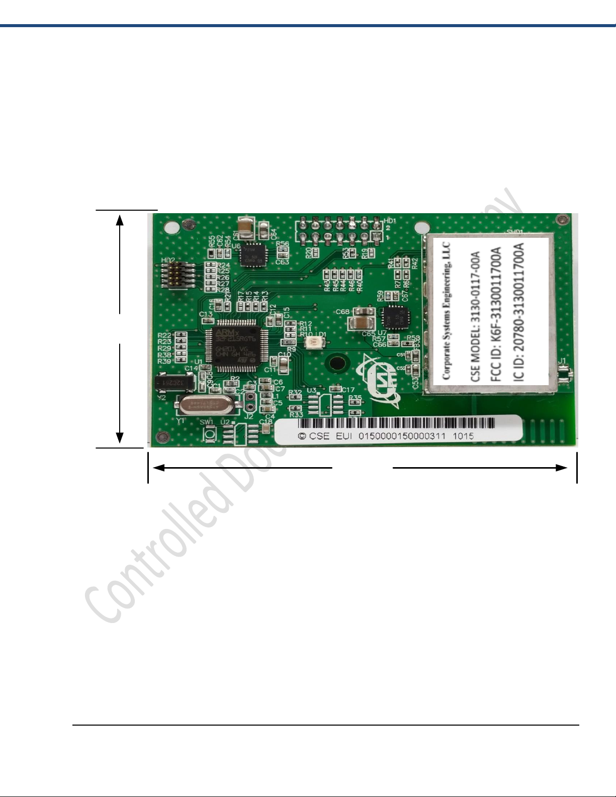
2.275"
3.430"
HD1 PINOUT
P1_5v
P3_NC
P5_NC
P2_NC
P4_IO
P6_GND
P7_GND
P8_IO
P9_NC P10_NC
P11_IO P12_RxD
P13_TxD
P14_NC
Connect Pin 12 to TxD of users MCU
Connect Pin 13 to RxD of users MCU
Demo Kit has 3.3v USB Cable provided.
5v 1A Desktop Power Supply Provided.
COMMUNICATIONS BOARD
CORPORATE SYSTEMS ENGINEERING
Corporate Systems Engineering Proprietary and Confidential
CISCO USER MANUAL 9
D030416-01661V1-00 February 2016
Page 10
CORPORATE SYSTEMS ENGINEERING
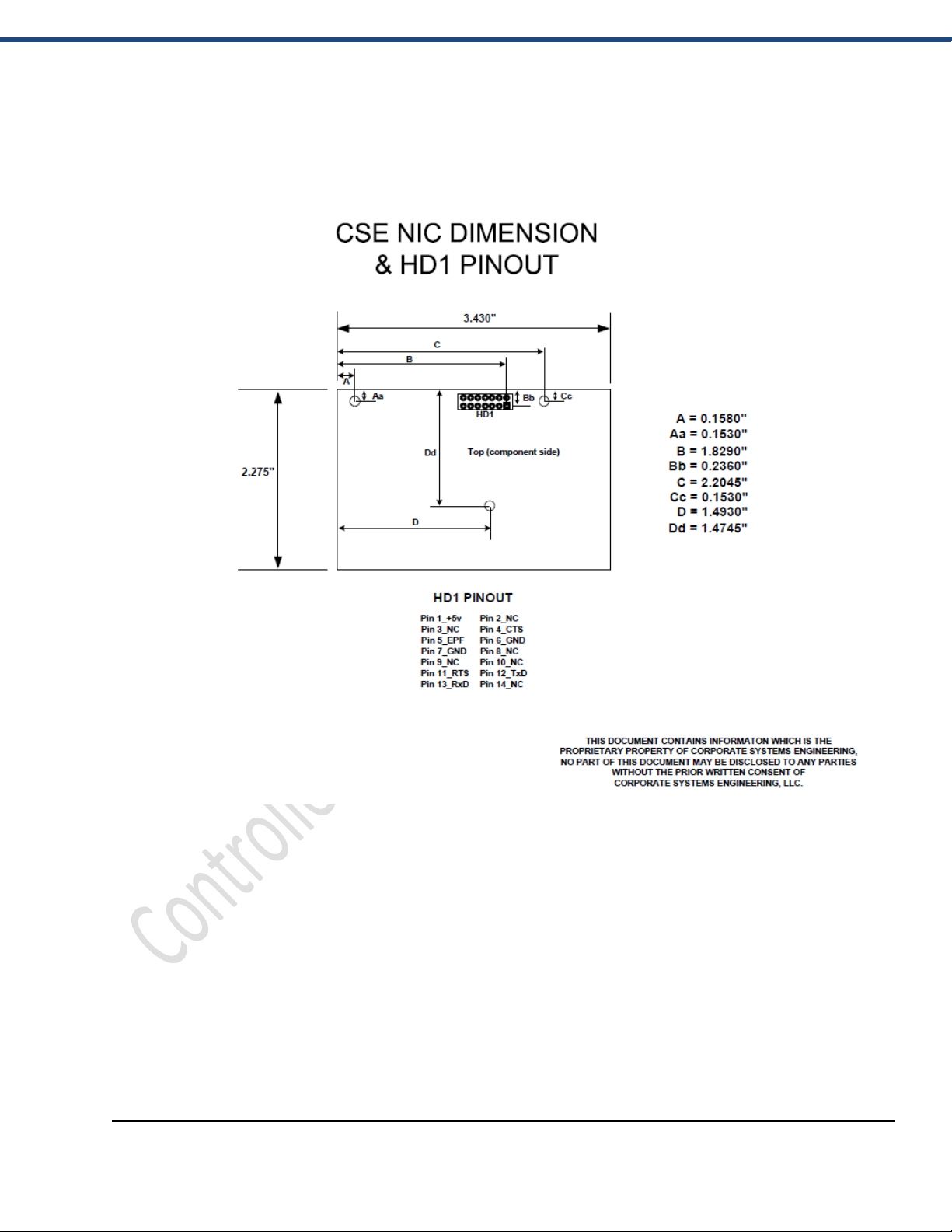
COMMUNICATIONS BOARD DIMENSIONS
Corporate Systems Engineering Proprietary and Confidential
CISCO USER MANUAL 10
D030416-01661V1-00 February 2016
Page 11

CORPORATE SYSTEMS ENGINEERING
FCC:
This device complies with Part 15 of the FCC Rules. Operation is subject to the following two
conditions:
1. This device may not cause harmful interference, and
2. This device must accept any interference received, including interference that may cause undesired
operation.
Changes or modifications not expressly approved by the party responsible for compliance could
void the user’s authority to operate the equipment.
FCC Interference Statement (Part 15.105 (b))
This equipment has been tested and found to comply with the limits for a Class B digital device,
pursuant to Part 15 of the FCC Rules. These limits are designed to provide reasonable protection
against harmful interference in a residential installation. This equipment generates uses and can
radiate radio frequency energy and, if not installed and used in accordance with the instructions, may
cause harmful interference to radio communications. However, there is no guarantee that
interference will not occur in a particular installation. If this equipment does cause harmful
interference to radio or television reception, which can be determined by turning the equipment off
and on, the user is encouraged to try to correct the interference by one of the following measures:
- Reorient or relocate the receiving antenna.
- Increase the separation between the equipment and receiver.
- Connect the equipment into an outlet on a circuit different from that to which the receiver is
connected.
- Consult the dealer or an experienced radio/TV technician for help.
Corporate Systems Engineering Proprietary and Confidential
CISCO USER MANUAL 11
D030416-01661V1-00 February 2016
Page 12

CORPORATE SYSTEMS ENGINEERING
Industry Canada:
This Device complies with Industry Canada License-exempt RSS standard(s). Operation is subject to
the following two conditions: 1) this device may not cause interference, and 2) this device must
accept any interference, including interference that may cause undesired operation of the device.
Cet appareil est conforme avec Industrie Canada, exempts de licence standard RSS (s). Son
fonctionnement est soumis aux deux conditions suivantes: 1) ce dispositif ne peut pas causer
d'interférences, et 2) ce dispositif doit accepter toute interférence, y compris les interférences qui
peuvent causer un mauvais fonctionnement de l'appareil.
Under Industry Canada regulations, this radio transmitter may only operate using an antenna of a
type and maximum (or lesser) gain approved for the transmitter by Industry Canada. To reduce
potential radio interference to other users, the antenna type and its gain should be so chosen that the
equivalent isotropically radiated power (e.i.r.p.) is not more than that necessary for successful
communication.
En vertu de la réglementation d'Industrie Canada, cet émetteur radio risquera uniquement à l'aide
d'une antenne de type et de gain maximum (ou moins) pour l'émetteur a approuvé par Industrie
Canada. Pour réduire les interférences radio potentielles à d'autres utilisateurs, le type d'antenne et
son gain doivent être choisie que la puissance isotrope rayonnée équivalente (p.i.r.e.) n'est pas plus
que celui nécessaire à une communication efficace.
OEM Responsibilities to comply with FCC and Industry Canada Regulations
The 3130-0117-00A Radio Module has been certified for integration into products only by OEM
integrators under the following conditions:
To comply with FCC RF exposure limits for general population / uncontrolled exposure, the
antenna(s) used for this transmitter must be installed to provide a separation distance of at least
10cm from all persons and operating in conjunction with any other antenna or transmitter.
To comply with Industry Canada RF exposure limits for general population / uncontrolled
exposure, the antenna(s) used for this transmitter must be installed to provide a separation distance
of at least 20cm from all persons and must not be operating in conjunction with any other antenna
or transmitter
If the module is used in a multi-transmitter or simultaneous transmission host then the module must
be evaluated and approved to one of the host platform exposure conditions. (Mobile exposure,
Portable exposure or Mixed Mobile and Portable exposure).
However, the OEM Intergator is still responsible for testing their end-product for any additional
compliance requirements required with this module installed (for example, digital device emissions,
PC peripheral requirements, etc.).
Corporate Systems Engineering Proprietary and Confidential
CISCO USER MANUAL 12
D030416-01661V1-00 February 2016
Page 13

CORPORATE SYSTEMS ENGINEERING
IMPORTANT NOTE: In the event that this condition cannot be met (for certain configurations
or co-location with another transmitter), then the FCC and Industry Canada authorizations are no
longer considered valid and the FCC ID and IC Certification Number cannot be used on the final
product. In these circumstances the OEM integrator will be responsible for re-evaluating the end
product (including the transmitter) and obtaining a separate FCC and Industry Canada
authorization.
Responsabilités OEM se conformer aux règlements de la FCC et Industrie Canada
Le Module Radio 3130-0117-00A a été certifié pour l'intégration dans des produits que par les
intégrateurs OEM dans les conditions suivantes:
Pour se conformer aux limites d'exposition aux RF de la FCC Canada pour la population générale /
exposition non contrôlée, l'antenne (s) utilisé pour cet émetteur doit être installé pour fournir une
distance de séparation d'au moins 10cm de toutes les personnes et opérant en conjonction avec une
autre antenne ou émetteur.
Pour se conformer à Industrie Canada RF limites d'exposition pour la population générale /
exposition non contrôlée, l'antenne utilisée pour ce transmetteur doit être installée pour fournir une
distance d'au moins 20 cm de toute personne et ne doit pas fonctionner en conjonction avec toute
autre antenne ou transmetteur.
Si le module est utilisé dans un environnement multi-émetteur ou hôte de la transmission simultanée
alors le module doit être évaluée et a approuvé l'une quelconque des conditions d'exposition de la
plate-forme d'accueil. (Exposition mobile, l'exposition portable ou l'exposition mobile et portable
mixte).
Toutefois, l'intégrateur OEM est toujours responsable de tester leur produit final pour toutes les
exigences de conformité supplémentaires nécessaires avec ce module installé (par exemple, les
émissions de périphériques numériques, les exigences périphériques de PC, etc.).
NOTE IMPORTANTE: Dans le cas où cette condition ne peut être respectée (pour certaines
configurations ou co-location avec un autre émetteur), les autorisations de la FCC et d'Industrie
Canada ne sont plus considéré comme valide et la FCC ID et IC Nombre de certification ne peut
pas être utilisé sur le produit final. Dans ces circonstances, l'intégrateur OEM sera chargé de
réévaluer le produit final (y compris l'émetteur) et l'obtention d'une autorisation distincte FCC et
d'Industrie Canada.
Corporate Systems Engineering Proprietary and Confidential
CISCO USER MANUAL 13
D030416-01661V1-00 February 2016
Page 14

CORPORATE SYSTEMS ENGINEERING
End Product Labeling
The 3130-0117-00A Radio Module is labeled with its own FCC ID and IC Certification Number. If
the FCC ID and IC Certification Number are not visible when the module is installed inside another
device, then the outside of the device into which the module is installed must also display a label
referring to the enclosed module. In that case, the final end product must be labeled in a visible area
with the following:
“Contains Transmitter Module FCC ID: K6F-3130011700A”
“Contains Transmitter Module IC: 20780-3130011700A”
or
“Contains FCC ID: K6F-3130011700A”
“Contains IC: 20780-3130011700A”
Le module de 3130-0117-00A est étiqueté avec son propre ID de la FCC et IC numéro de
certification. L'ID de la FCC et IC numéros de certification ne sont pas visibles lorsque le module
est installé à l'intérieur d'un autre appareil, comme par exemple le terminal dans lequel le module est
installé doit afficher une etiquette faisant référence au module cijoint. Le produit final doit être
étiqueté dans un endroit visible par le suivant:
“Contient Module émetteur FCC ID: K6F-3130011700A"
“Contient Module émetteur IC: 20936-3130011700A”
ou
“Contient FCC ID: K6F-3130011700A”
“Contient IC: 20936-3130011700A”
The OEM integrator has to be aware not to provide information to the end user regarding how to
install or remove this RF module or change RF related parameters in the user manual of the end
product.
L'intégrateur OEM ne devraient pas fournir des informations à l'utilisateur final sur la façon
d'installer ou de supprimer ce module RF ou modifier les paramètres liés RF dans le manuel
utilisateur du produit final.
Corporate Systems Engineering Proprietary and Confidential
CISCO USER MANUAL 14
D030416-01661V1-00 February 2016
Page 15

CORPORATE SYSTEMS ENGINEERING
To comply with FCC RF exposure limits for general population / uncontrolled exposure, the
antenna(s) used for this transmitter must be installed to provide a separation distance of at least
10cm from all persons and operating in conjunction with any other antenna or transmitter.
To comply with Industry Canada RF exposure limits for general population / uncontrolled
exposure, the antenna(s) used for this transmitter must be installed to provide a separation distance
of at least 20cm from all persons and must not be operating in conjunction with any other antenna
or transmitter.
Pour se conformer à Industrie Canada RF limites d'exposition pour la population générale /
exposition non contrôlée, l'antenne utilisée pour ce transmetteur doit être installée pour fournir une
distance d'au moins 20 cm de toute personne et ne doit pas fonctionner en conjonction avec toute
autre antenne ou transmetteur.
Corporate Systems Engineering Proprietary and Confidential
CISCO USER MANUAL 15
D030416-01661V1-00 February 2016
Page 16

NOTES:
CORPORATE SYSTEMS ENGINEERING
Corporate Systems Engineering Proprietary and Confidential
CISCO USER MANUAL 16
D030416-01661V1-00 February 2016
 Loading...