

Page 1

1
User's Manual
(Outdoor MD IP Camera Series)
Firmware V0.95
Please read this manual car ef ul l y before you attempt to
Install this product and retain it for your future reference.
Page 2

2
Contents
Main Features .............................................................................................................................................................................. 5
Physical Description ..................................................................................................................................................................... 8
Installation ................................................................................................................................................................................. 12
Hardware Installation ........................................................................................................................................................ 12
Outdoor IP Camera Connecting Guide .............................................................................................................................. 14
Network Camera with PoE Function ................................................................................................................................. 15
Camera setup installation & Usage ................................................................................................................................... 16
Assigning an IP address to the Camera with Camera Setup .............................................................................................. 19
Network Camera Screen and Setup W indow ............................................................................................................................. 21
Viewing the camera from your mobile phone ........................................................................................................................... 25
Network Camera Setting Interface ............................................................................................................................................. 26
Camera ....................................................................................................................................................................................... 28
Camera Setup ................................................................................................................................................................... 28
Stream Setup .................................................................................................................................................................... 29
OSD Setup ......................................................................................................................................................................... 32
Night Vision Setup (IR IPCAM) .......................................................................................................................................... 33
Network ..................................................................................................................................................................................... 34
Wireless Setup .................................................................................................................................................................. 34
TCP/IP Setup ..................................................................................................................................................................... 36
PPPoE Setup ...................................................................................................................................................................... 38
DDNS Setup ....................................................................................................................................................................... 39
UPNP Setup ....................................................................................................................................................................... 40
Alarm ......................................................................................................................................................................................... 43
Motion Detection .............................................................................................................................................................. 43
Schedule Setup
Alarm Management .......................................................................................................................................................... 46
Periodic Sending ............................................................................................................................................................... 48
Buffer Management .......................................................................................................................................................... 50
Alarm Server .............................................................................................................................................................................. 51
FTP Server ......................................................................................................................................................................... 51
e-Mail Server .................................................................................................................................................................... 52
HTTP Server ...................................................................................................................................................................... 53
Stora ge ....................................................................................................................................................................................... 54
Record on Alarm ............................................................................................................................................................... 55
Snapshot on Alarm ............................................................................................................................................................ 56
Continuous Record ............................................................................................................................................................ 57
Snapshot at Interval .......................................................................................................................................................... 58
FTP Sending ...................................................................................................................................................................... 59
Browse Storage ................................................................................................................................................................. 60
Format SD Card ................................................................................................................................................................. 61
Tools ........................................................................................................................................................................................... 62
System Identity ................................................................................................................................................................. 62
User Management ............................................................................................................................................................ 63
Date & Time ...................................................................................................................................................................... 64
Backup or Reset ................................................................................................................................................................ 65
Firmware Upgrade ............................................................................................................................................................ 66
SPEEDREAD YOUR NETWORK CAMERA ...................................................................................................................................... 67
Wizard .............................................................................................................................................................................. 67
System
Support ............................................................................................................................................................................. 68
Reboot .............................................................................................................................................................................. 68
ADVANCED SETTINGS ................................................................................................................................................................. 69
Port Forwarding ................................................................................................................................................................ 69
Proxy Server Setting .......................................................................................................................................................... 70
Reset the camera .............................................................................................................................................................. 71
CONNECTED DIRECTLY TO A COMPUTER ................................................................................................................................... 72
DEFAULT SETTINGS ..................................................................................................................................................................... 73
SPECIFICATIONS ......................................................................................................................................................................... 77
TROUBLESHOOTING ................................................................................................................................................................... 78
GLOSSARY OF TERMS ................................................................................................................................................................. 79
................................................................................................................................................................. 45
.............................................................................................................................................................................. 68
Page 3

3
INTRODUCTION
Thank you for your interest and support in our product and purchasing this outdoor camera. The camera can be
accessed remotely, and controlled from any PC/laptop over the Intranet or Internet via web browser. The
user-friendly installation procedure and intuitive web-based interface offer easy integration with your LAN
environment or WiFi system. Meanwhile, the IP66-rated integrated housing shields the camera from dust and
water, allowing it to be applied in the harsh weather conditions of outdoor environments.the camera also comes
with a lot of useful alarm tool for notice user any situation. We feel confident that you will be pleased with the
quality and features of this product.
Notice
This product may cause interferences with other wireless equipment that operates at 2.4GHz ISM band. Please
turn off one of the equipments to eliminate the interference.
Product Assurance
This camera will emit electromagnetic wave, just like other wireless products, but its transmitting power is
less than other wireless products such as mobile phones. The 2.4GHz wireless camera meets wireless
frequency security standards and recommended indexes while working. These standards and indexes are
certificated by academic organization and represent the cogitative research of the scientific workers who
continuously explore and annotate the involved fields. So we believe that our products are safe for
customers.
Approval Information
All our products meet the requirements of approval FCC or CE, and are granted the FCC or CE
certification. They are authorized to bear FCC or CE mark.
FCC
This equipment has been tested and found to comply with the limits for a Class B digital device, pursuant to
Part 15 of the FCC rules. These limits are designed to provide reasonable protection against harmful
interference in a residential installation. This equipment generates, uses and can radiate radio frequency
energy and, if not installed and used in accordance with the instructions, may cause harmful interference to
radio communications. However, there is no guarantee that interferenc e w ill not occur in a parti cul ar
installation. If this equipment does cause harmful interference to radio or television reception, which can be
determined by turning the equipment off and on, the user is encouraged to try to correct the interference by
one or more of the following measures: -Reorient or relocate the receiving antenna. -Increase the separation
between the equipment and the receiver. -Connect the equipment into an outlet on a circuit different from
that to which the receiver is connected. -Consult the dealer or an experienced radio/TV technician for help.
This device complies with Part 15 of the FCC Rules. Operation is subject to the following two conditions:
(1) This device may not cause harmful interference, and
(2) this device must accept any interference received, including interference that may cause undesired
operation Changes and modification not expressly approved by the manufacturer or registrant of this
equipment can void your authority to operate this equipment under Federal Communications Commissions
rules.
CE
This product complies with standards including Low Voltage Device Directive 73/23/EEC; EMC
Directive 89/336/EEC and R&TTE Directive 1999/5/EC. It passed the subject tests by the authority
concerned and is authorized to bear CE mark.
Page 4

4
Restrictions
1. DO NOT use this product to violate one's privacy. Monitoring one's activities without consent is illegal
and this product is not designed and manufactur ed for such p urpos e.
2. DO NOT put this product near any medical equipment. Radio waves might potentially cause breakdown
of electrical medical equipment.
3. This product should be placed at least 1 foot away from any heart pacemaker. Radio waves might
potentially influence heart pacemaker.
4. DO NOT use this product for any illegal activities. It is the user’s responsibility to ensure that the
usage of this camera is of a legal nature.
Maintenance
1. Ensure that the camera and its power source have sufficient ventilation;
2. Do not shake, strike or drop the product;
3. Keep the camera dry and dustless and avoid exposin g it to dir ect sunlig ht ;
4. Do not place the product near any magnetic obje cts;
5. Avoid putting the product in places where there is constant temperature and humidity change;
6. Keep the product away from heat sources;
7. Do not use the camera near aggressive chemicals;
8. Do not use this camera near water;
9. Do not use the camera in the places which are enclosed by metal. The surrounding metal may shield
the electromagnetic waves, and result in failure of signal reception;
10. Please obey the local government's environment protection policy;
11. Please turn off the power when left unused;
12. Do not disassemble or attempt to repair the camera; doing so might cause damage to the product.
Page 5

5
Main Features
Easy Installation
The camera comes with built-in Wireless (IEEE802.11b/g) capability and a Web Server, therefore there
is no need to install a driver. The setup CD-ROM includes the Camera Setup software, User Manual
and Quick Installation Guide.
With industry standard automatic configuration-UPnP(Universal Plug and Play), your PC will discover and
connect to your camera automatically. Once connected, using a simple Web browser you can see what the
camera sees from anywhere in the world!
The camera can be either wall-mounted or ceiling-mounted using the supplied stand. It can also be
placed on a desktop using the supplied stand, thus providing a flexible installation solution.
PoE Function
The Network Camera is with POE function, which allows it to be powered via a single Ethernet cable.
you do not need to use the power plug.but your switch/router must be support PoE.
802.11b/g/n Wireless LAN Connection Available
The camera is designed to not only work with your existing wired network but also with standard 802.11b/g
wireless devices, allowing the flex ibility to operate t he camera wirelessly. The camera utilizes SSID filtering,
powerful 64/128 bit WEP and new security standard WPA encryption to protect you from illegal intrusion.
3GPP Mobile Surveillance
The camera provides the ability to view the cameras monitored through your mobile phone as a live video
stream, it supports the telecommunications standard of 3GPP streaming format. All 3G enabled mobile devices
and most 2G phones that support the streaming standard of 3GPP are compatible.
Simultaneous High-Speed MPEG-4 and Motion JPEG
The camera allows live the M PE G -4 and Motion JPEG streams simultaneously. The camera features MPEG4
compression which compresses the video to make transmission faster and more efficient . T he MPE G 4 and
MJPEG image can be transmitted at 30 frames per second.
Simultaneous HTTP and RTSP streaming
The camera support HTTP and RTSP/RTP/RTCP protocol, and provide multiple HTTP and RTSP streams
simultaneously.
Audio Transmission
The camera comes with a built-in microphone for audio monitoring as well as video monitoring. Sound
captured by the camera is transmitted to the client’s PC.
Snapshot and Recording
You can capture a still image of the camera view on your PC and save the image as JPG or BMP format file.
You also can record the video and audio captured by the camera on your PC and save as an ASF format file.
Page 6

6
Motion Detection Function
The camera can detect changes in the image being monitored. Once a change occurs it will send an email to
up to 3 email addresses with a video file or snapshot attached. The video file or snapshot can also be
uploaded to an FTP server. In addition the camera can be configured to send images at regular intervals.
OSD Function
OSD (On Screen Display) function can display system name, date and time, and user-defined on screen.
Authentication
An authentication window requires you to enter the user ID and password. Password security can prevent
unregistered users from accessing your camera. Users can select Basic Authentication method or Digest
Access Authentication method .
Multi-Client Access
The camera allows up to 16 users to view the video simultaneously. Please note that it is possible that as the
number of simultaneously connected users to camera increases, the overall motion performance will decrease.
Infrared Night Vision (IR-CUT)
The camera built-in IR-Cut which is prevent the image to happen color cast during daytime ,it can be switching
and filter infrared light in day/night.
The camera utilizes 12 infrared LED to provide high light in darks environme nt .when the environment is dark,
the LED will be opened automatically due to a photosensitive component, and the moving images will be
changed to Black and White. Users can monitor clearly the things within 15 meters distance. Users also can
select open or close the infrared LED manually, and select whether change the images to black and white or
color automatically.
Page 7

7
Adapter
This product conforms with the authenticated AC adapter. The adapter is marked with one or more of the
following:
Note: When using the power adapter, make sure the rating voltage on it is compatible with that of the device
to avoid potential damages resulting from incorrect usage of power supply.
PC System Requirements
The PC (Personal Computer) and the network must meet the following technical specifications for camera to
work properly.
1. Processor: Intel Pentium III, 1GHz or Higher (Pentium IV, 2 GHz or Higher
recommended)
2. RAM: 256 MB or more
3. Color Monitor: Suggest at least 1024x768 and the latest driver for the Display Adapter
4. OS (Operating System): Windows XP/Vista/7, MAC OS, Linux, Android, iPhone OS, Windows
Mobile, BlackBerry OS
5. Web Browser: Microsoft IE, Safari, Mozilla Firefox, Google Chrome and most other
browsers
6. Network Protocol: TCP/IP network protocol installed
7. Interface: 10/100 Mbps Ethernet® card/Wireless Network card for your network
connection
8. Other: CD-ROM Drive
Page 8

8
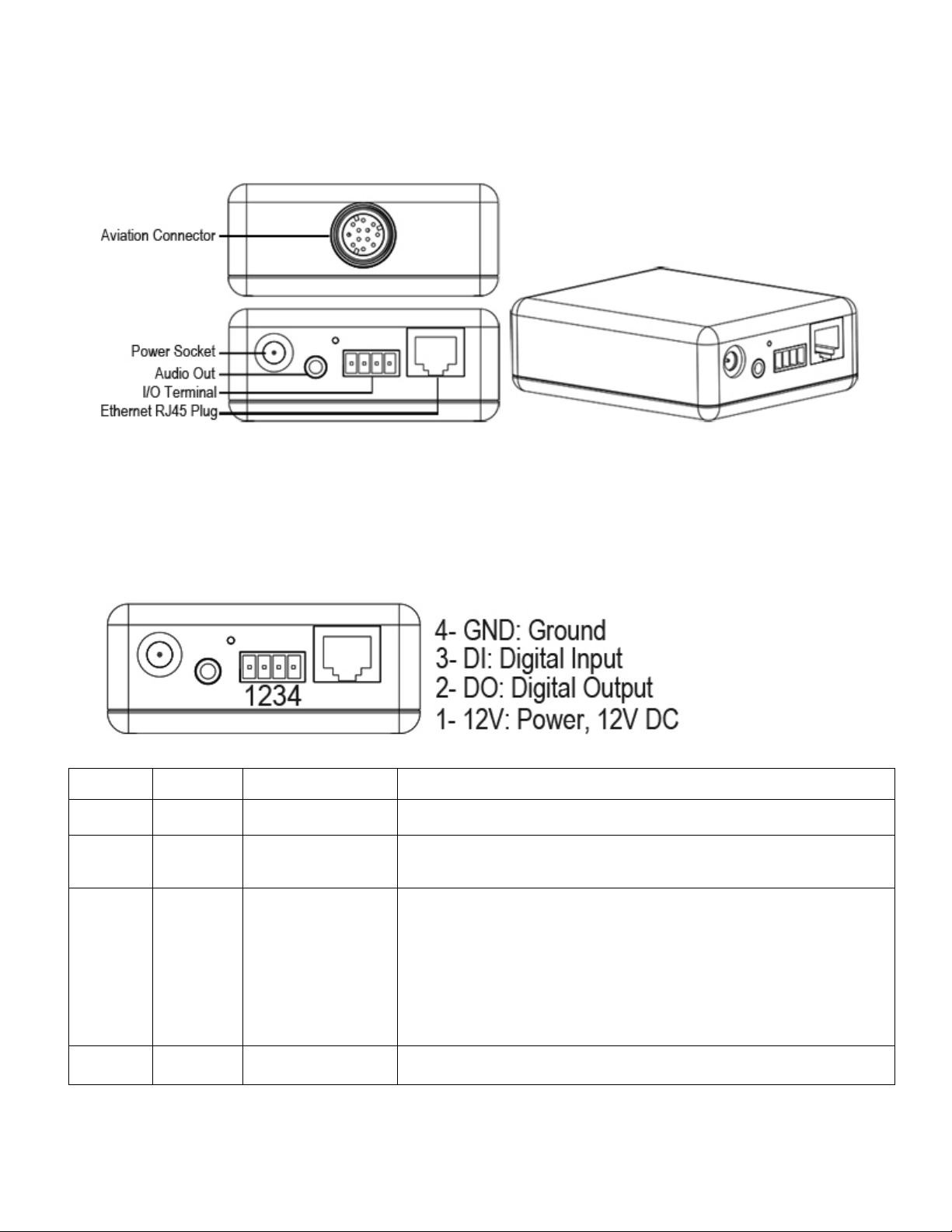
Physical Description
Front panel
Connectors
Page 9
9
collector NPN Darlington transistor with the
If used with an external relay,a diode must be connected in
Adapter Box
General I/O Terminal Block
This Network Camera provides a general I/O terminal block which is used to connect external input / output devices. The pin
definitions are described below .
Pin No. Pin Name Function Description
4 GND Ground This is a signal ground use for DI and DO
3 DI Digital Iutput Connect to GND to activate or deactivate by software set t ing
With a maximum load of 1A and maximum voltage of 60V DV,this
output has an open-
2 DO Digital Output
1 12V Power +12V 12VDC ± 10%, max. 0.4A
emitter to the GND pin.
parallel with the load,for p r otection against voltage transients.
Page 10

10
DI/DO Diagram
Please refer to the following illustration for the connection method.
Page 11

11
Status LED
The LED indicates the status of the Network Camera.
1) Green LED - Power is being supplied to the Network Camera.
2) Blinking Orange LED – IP camera has been connected and data is present.
Hardware Reset
The Reset button is used to restore the factory default settings. Sometimes resetting the system can return the camera to normal
operation.
Restore - Press and release the reset button with a paper clip or thin object. The LED light will be out, after few seconds it will
relight again. (Note: that all settings will be restored to factory default)
Page 12

12
Installation
Hardware Installation
Follow the steps below to install the Network Camera:
1. Open the lens cover.
2. Secure the Network Camera to the supplied camera stand as the illustration shows.
3. Secure the Network Camera to the wall/ceiling by the supplied camera stand.
4. Open the lens cover and insert “SD card” then tighten the lens cover.
Page 13

13
Note
If you want to use the supplied sun shield for outdoor environments, please follow the steps
below to install:
1. Atta ch the supplied sun shield to the Network Camera and slide it to the desired position.
2. Fix the sun shield with supplied screws and washers. (Please use different screws for ceiling mount.
3. Secure the Network Camera to the wall/ceiling by the supplied camera stand.
Page 14
14
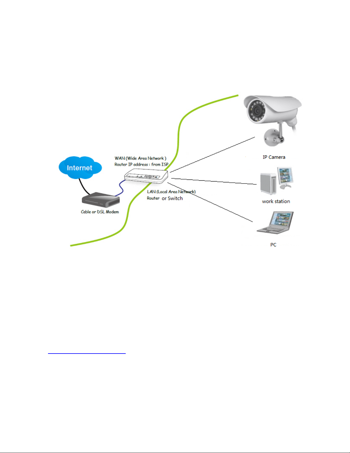
Outdoor IP Camera Connecting Guide
For initial setup, you need to connect the IP Camera directly to your router, switch or computer via a network cable. You cannot
connect wirelessly to the camera without first setting it up via a network cable.
You should connect the Camera into your internet router (normally supplied by your broadband provider), a switch box or hub (that
is connected to your computers network) or directly to your computer (gives limited viewing options, so this is not recommended).
Connection via a Router/Switch
1. Using the standard Ethernet network cable, plug this in to the network connection socket on the IP Camera at one end, and plug
the other end in to a spare port on your router/switch.
2. Using the Power Adaptor (supplied), plug one end in to the Power Connection socket on the IP Camera. Plug the other end in to
an electrical socket and turn the power on.
3. The Connectivity Status indicator on the front of the camera will light up. Your router/switch will then begin to communicate with
the camera.
Connection directly to a computer
Choose this connection for testing the IP Camera to avoid any interference from other equipment, please refer to
Chapter
Connected Directly to a Computer for details.
Page 15
15
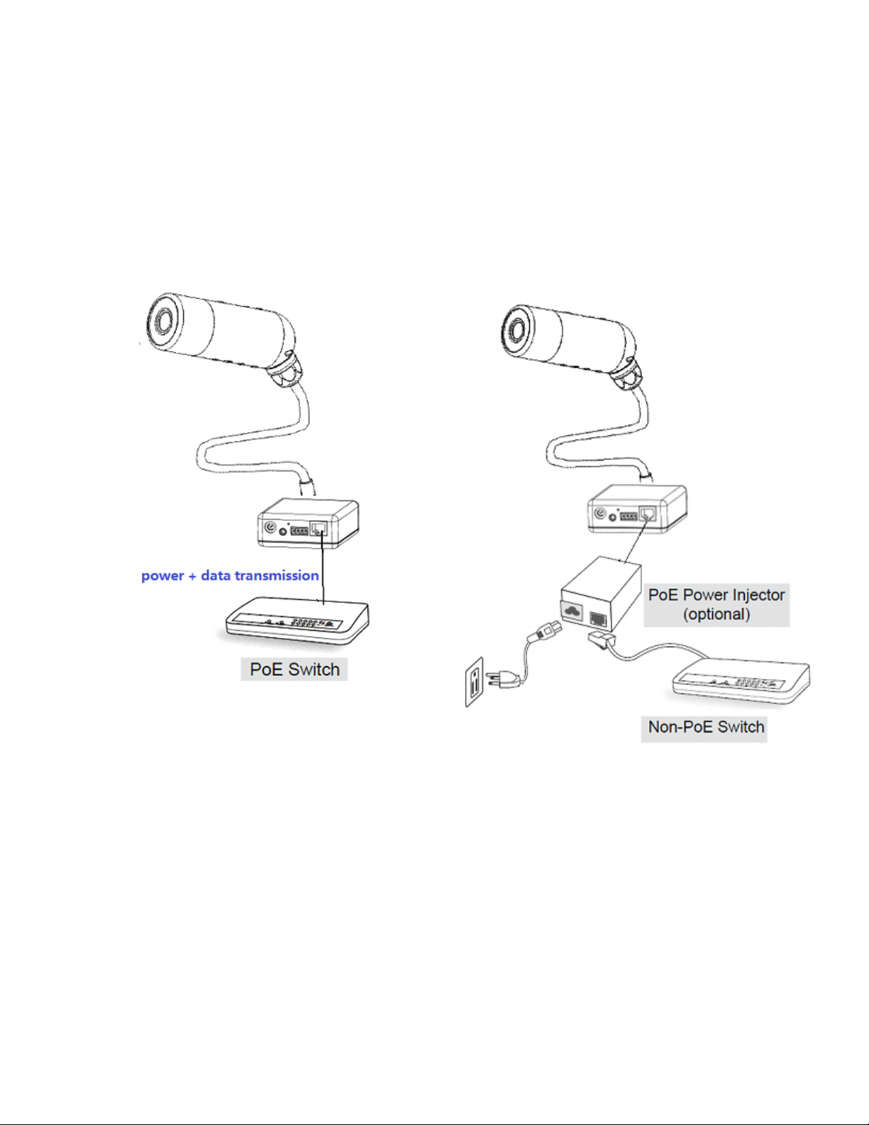
Network Camera with PoE Function
1. When using a PoE-enabled switch
2. When using a non-PoE switch
The Network Camera is PoE-compliant, which allows it to be
powered via a single Ethernet cable. if your switch/router
supports PoE, refer to the following illustration to connect the
Network Camera to a PoE-ena bled sw itch/router .
If your switch/router does not support PoE, use a PoE power
injector (optional) to connect between the Network Camera
and a non-PoE switch/router.
Page 16

16
Camera setup installation & Usage
The camera Setup utility can easily and quickly detect cameras connected to your local network and list
them on the Camera Setup window, also you can use the camera Setup utility to assign an IP address to
each camera.
1. Insert the Installation CD into your CD-ROM drive and the installation screen should appear
automatically (See image below). If it does not, click “Start” then “Run”. In the text field enter
“D:\autorun.exe” (if “D:” is the letter of your CD-ROM Drive)
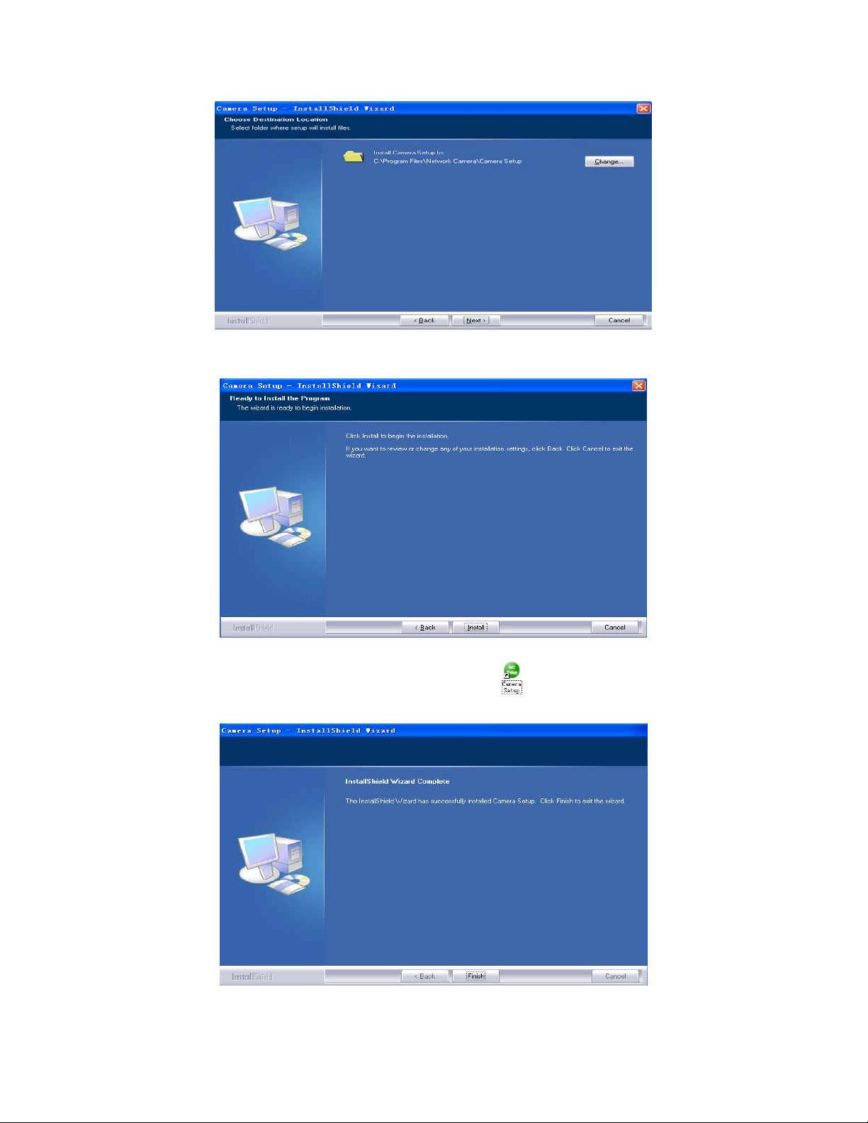
2. Click on “Install Camera Setup” and the following screen will be displayed.
3. If you want to change the default folder click “Change” to replace otherwise click “Next”
Page 17
17
4. Click Install to install Camera Setup.
5. Click Finish to end the installation. You should now find a icon on the desktop.
Page 18

18
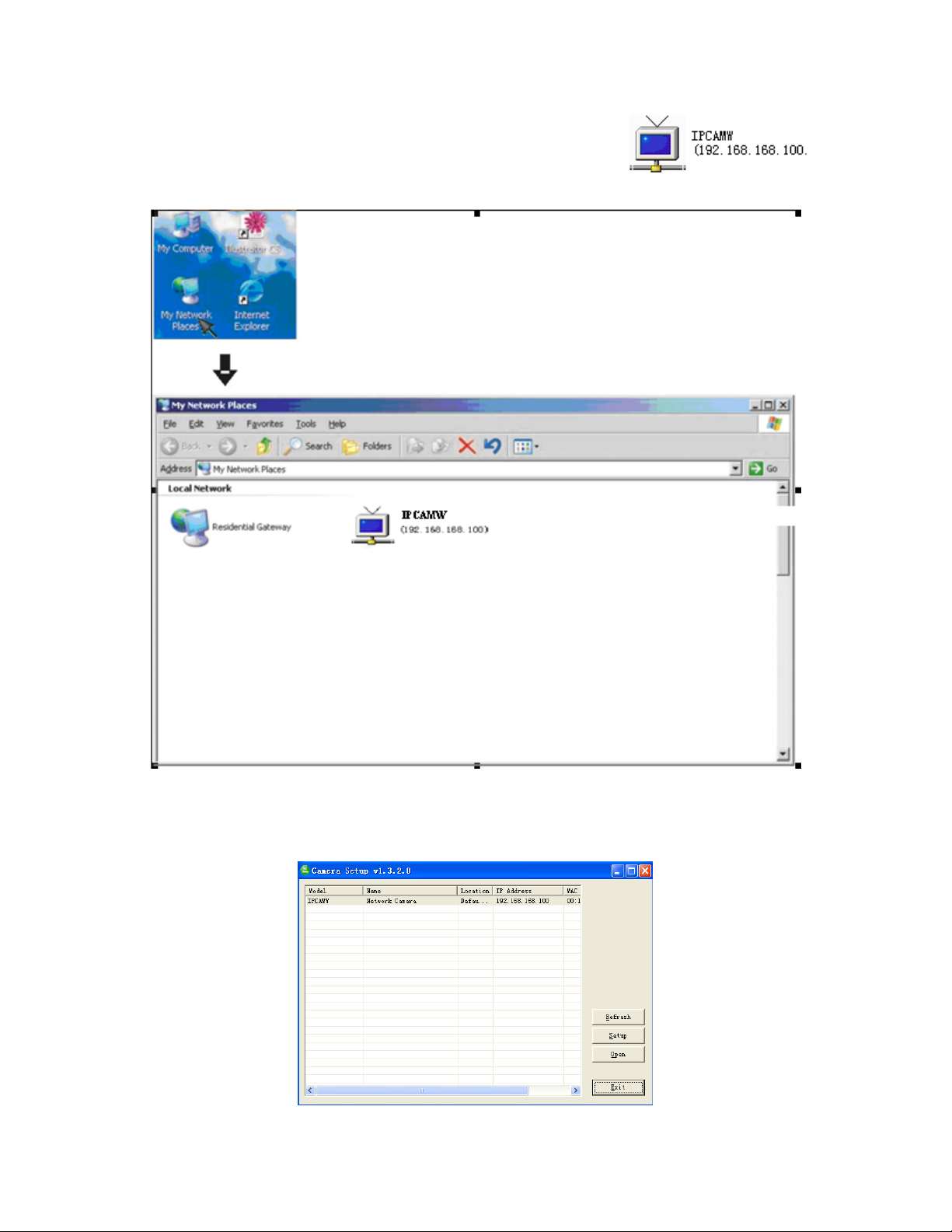
6. Double-click the Camera Setup icon on the Desktop to launch the program. The Camera Setup
utility should automatically find your camera if is correctly connected (See image below).
[Refresh] Click Refresh to search for cameras on the local network.
[Setup] Select the required camera and click Setup to configure the network settings for the camera.
[Open] Select the required camera and clic k Open to access the camera via a web browser.
[Exit] Click Exit to exit the Camera Setup window.
Note: Select and double click one of the cameras from the Device list, to open the camera view via the web
browser.
Page 19

19
Assigning an IP address to the Camera with Camera Setup
1. Launch Camera Setup program to detect cameras on the local network.
2. Click on “Setup” button and the following setup interface will pop up.
3. Enter a unique name for the camera, the location (optional) and leave the default port number as
80.“Obtain an IP address automatically” and “Obtain DNS server address automatically” are selected by
default, if you are confident enough to enter your own settings, you can do so by selecting “Use the following
IP address” and follow the guidelines on the next page. If however you wish to leave the default settings
please skip to NETWORK CAMERA SCREEN AND SETUP WINDOW.
4. To obtain the IP addresses specific to your network, click “Start” then “Run” and type “cmd” in the text box
and click “Ok”. The will bring up the MS-DOS prompt and in this window type “ipconfig/all” and press enter.
A screen similar to the one below will be displayed.
Page 20

20
5. Take note of the following:
i) IP Address
ii) Subnet Mask
iii) Default Gateway
iv) DNS Servers (Both numbers with the first being the primary DNS server and the second being
the secondary DNS server)
6. Enter the details noted in step 5 into the relevant fields.
Note: The default IP address of the camera is 192.168.168.100Th is can be change d to any IP addre ss on
your IP range. For example if the IP address of your PC is 192.198.1.52 then the IP address of your camera
should be unique and on the same subnet, i.e. 192.198.1.X where X is any number between 1 and 255
except 52. Ensure the IP address you chose is not the same as other network devices on your network as
this will result in conflict and may cause the device to not to work properly.
7. Once you’ve entered all the details click “Apply” then “Exit”.
Page 21
21
Network Camera Screen and Setup Window
Review Images from the Network Camera
You can select one of the three ways to review pictures from the camera.
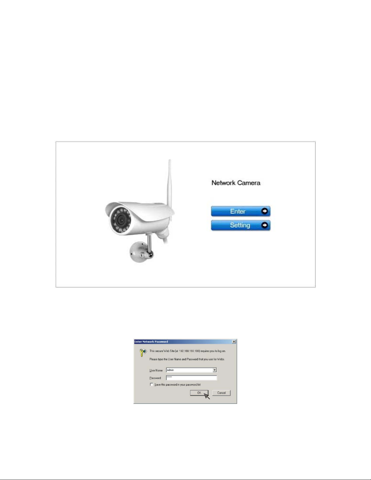
1. Input the assigned IP address (or URL) of the camera on the Web Browser. Take 192.168. 168.100 as
example. You will see the home page.
Notes:
Through this welcome page, you could choose to click on the item Enter to access the picture viewing
interface or the item Setting to access the system setting interface. The below dialog will appear. Input the
correct username (the default is admin, in lowercase) and password (the default is admin, in
lowercase). You are allowed to enter the picture viewing interface or the system setting interface.
The general users assigned by the administrator are not allowed to enter the system setting interface. They
can only be permitted to enter the picture viewing interface.
Page 22
22
2. If your OS is Windows XP, click [My Network Places], double click the icon
You will see the home page.
3. Run the Camera Setup and double-click the relevant camera item.
Page 23
23
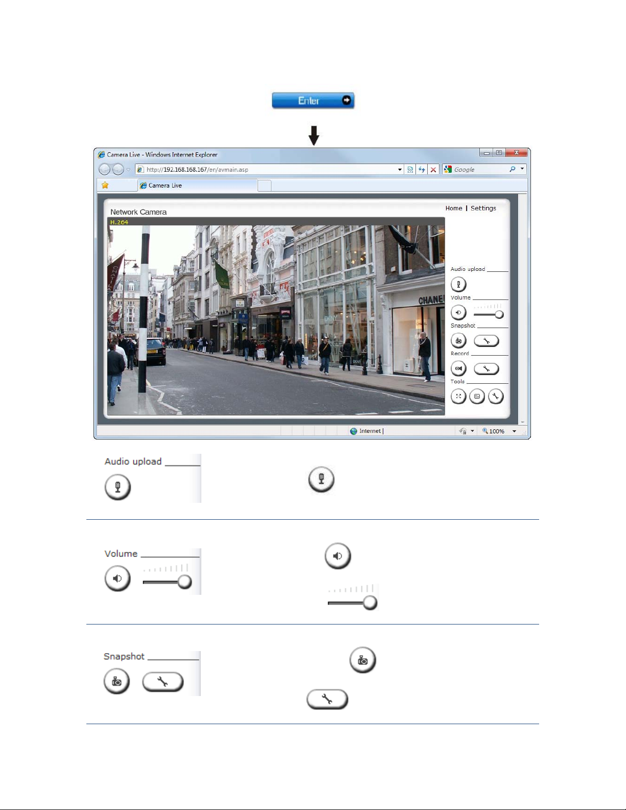
Click Enter, you will see the screen.
to start sending audio from your computer’s
Press and release to stop sending audio.
is automatically assigned the data & time of the snapshot.
[Audio Upload]
Press and release
microphone to the camera speakers.
[Volume]
1. Click the Mute button to mute the audio.
2. Slide the Slide block
[Snapshot]
1. Press the Snapshot button
view.
2. Press this button To change default Snapshot path, The file
horizontally to adjust volume.
to capture a still image of the camera
Page 24
24
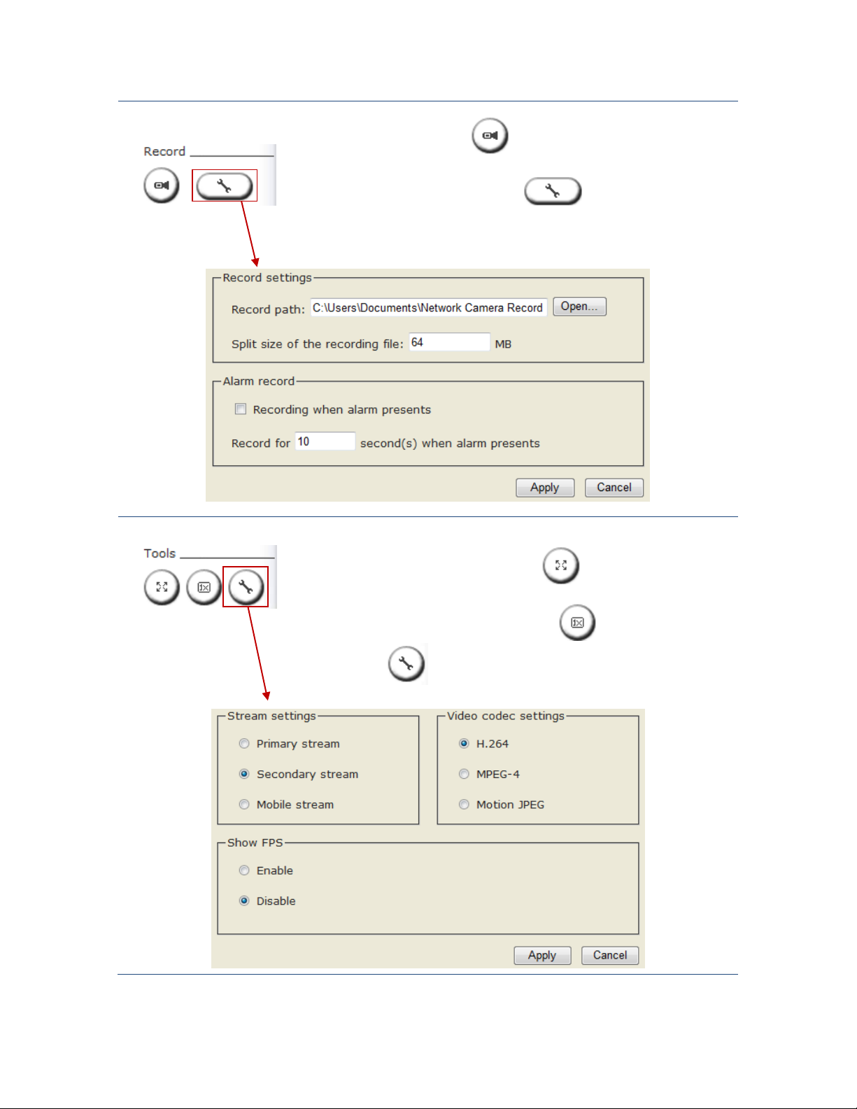
[Record]
recording in seconds.
Stream Type, Video Codec
1. Press the Record button to record video and audio.
2. Recording Config. Click this button
parameters, you can set record path, video file size and select whether to
start recording automatically when motion is detected and the length of the
[Tools]
1. For Full Screen mode click this button
It could also achieve s ame function by double click the Image Field.
2. For Fill up the Image field click this button .
to set the recording
, Press Esc to exit.
3. This button
for
Settings.
Page 25
25
Viewing the came ra from your mobile phone
The camera provides the ability to view the cameras monitored through your mobile phone as a live video
stream, it supports the telecommunications standard of 3GPP streaming format. All 3G enabled mobile
devices and most 2G phones that support the streaming standard of 3GPP are compatible. Otherwise, you
also can view the pictures even if your phone is not 3GPP compatible.
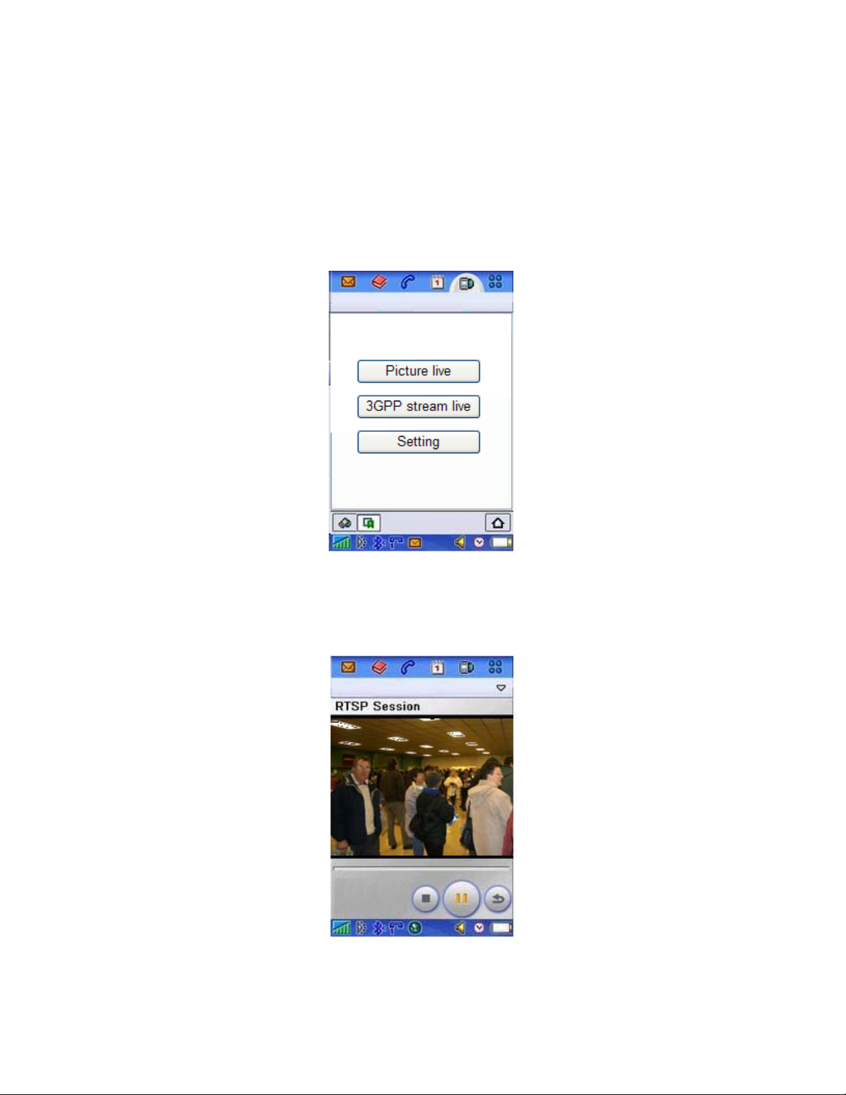
For example, if camera’s external IP address is 202.96.135.206 and external port is 8151, then type
http://202.96.135.206:8151/mobile in your Internet browser address bar of mobile phone, the login screen
will appear:
To click the “Picture live” button if your mobile phone is not 3GPP standard, then you can view the pictures
which will refresh every 3 seconds.
To click the “3GPP stream live” if your mobile phone support 3GPP standard, and the following screen will
appear:
Note: You have to click “Setting” button, make sure that the Mobile stream is enabled and the RTSP
authentication is disabled before you view the 3GPP stream live.
Page 26
26
Network Camera Setting Interface
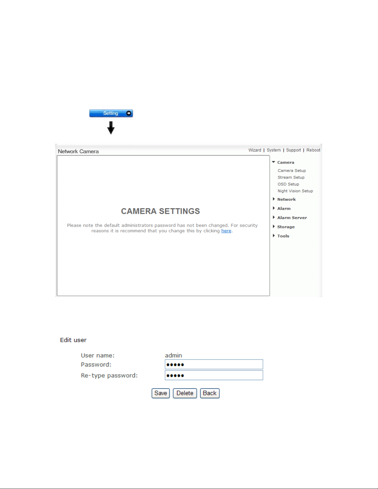
1. Click on settings from the home page. When connecting the camera for the first time or after resetting it
to its default settings, the setup interface start page below will load. It is recommend that you change the
admin password in order to avoid unauthorized access to the camera. To do this follow the instructions by
clicking on the underlined link “here” to access administrator password editing page.
2. Type the password in both fields then click Save. Please take note of the password. If you forget the
password, the camera will have to be reset to its default settings in order to gain access to the settings page
and this will also reset all other settings you may have changed.
3. You are required to re-login with the changed password.
Page 27

27
After successful login, the following page will appear.
Page 28

28
Camera
Camera Setup
From the home page click settings and enter the administrator user name and password. Click on Camera
Setup under the title Camera to change the image and audio parameters of the camera.
[Light frequency] Two options: 50Hz & 60Hz. Set according to the mains frequency in the country of use.
For UK this would be 50Hz.
[Image mirror] Image can be flipped from left to right.
[Image flip vertical] Image can be flipped up and down.
[Moonlight mode] Turn On/OFF the brightness setting according to the light intensity of the area being
monitored manually. [Auto] automatic enhance ambient brightness when it is necessary.
[Power LED light] Turn on/off the power & network LED indicator of camera.
[Show FPS in ActiveX]Show FPS On/Off in ActiveX control.
[Microphone] Turn on/off the built-in microphone.
[Mic volume] Adjusts the volume of the microphone from 0~14 where 0 is the lowest.
[Audio bit rate] Four options: 16, 24, 32, 40(kbps). Determines the quality of the audio being transmitted.
[AMR bit rate] Eight options will Determines the quality of the audio being transmitted.
Click Apply to confirm your settings.
Note: If the camera is inversely installed, images flip horizontally and images flip vertically should be
turned on at the same time.
Page 29

29
Stream Setup
The camera supports three streams: primary stream, secondary stream and mobile stream.
Page 30

30
[Image size] Three image resolutions available: 1280 x 720, 640 x 352, 320 x 176.
[Frame rate] Twelv e options: 1/ 2/3/ 4/5/6/8/10/15/20/25/30 frames per second (fps).
[MPEG4 bit rate] Select MPEG4 bit rate. Eight options: 64, 128, 256, 512, 768, 1024, 1536, 2048 (kbps).
[MJPEG quality] Type in MJPEG video quality value (20 – 100), 20 is low quality, 100 is high quality.
[Snapshot quality] Type snapshot quality. (20 – 100), 20 is low quality, 100 is high quality.
The above five settings determine the image quality, however higher bit rates require greater bandwidth.
Please select the appropriate settings according to your connection speed and network traffic. If you are
experiencing jerky video it may be necessary to decrease the bit rate.
[Audio] Enable or disable audio.
[RTSP authentication] Enable or disable RTSP authentication.
You can use Mobile phone t o play the mobile stream from cam era, but generally Mobile phone do not
support authentication, so we have to disable the RTSP authentication.
Page 31

31
A stream list page will be shown after clicking the stream name such as “Primary stream”.
[Primary stream] cannot be disabled.
A sample of primary stream list as below:
You can use RealPlayer, VLC Player or QuickTime Player to play the live stream from camera in
Intranet or Internet.
[Secondary stream] Enable or disable secondary stream.
[Mobile stream] Enable or disable Mobile stream.
You can use mobile phone, Real player and QuickTime Player to play the live stream from camera.
The size of video is 176 x 144.
Click Apply to confirm your setting.
Page 32

32
OSD Setup
This function can display system name, date and time, or use-defined on screen.
[OSD] Enable or disable OSD function.
[Transparent] Users can select whether cha nge OSD to tra nspar ent or not.
[Display date and time] O SD is date and time of camera.
[Display system name] OSD is system name of camera.
[Display the text below] OSD is user-defined text.
[Display the text below with date and time] OSD is user-defined text with date and time of camera.
Click Apply to confirm your settings.
Page 33

33
Night Vision Setup (IR IP CAM )
Only IR IPCAM have infrared LED, which can be opened automatically when camera check dark
environment.
[Infrared LED control] When the environment is dark, the LED will be opened automatically due to a
photosensitive component. Users also can select open or close the infrared LED manually.
[Black and white mode] When the environment is dark, the moving images will be changed to Black and
White automatically. Users also can select whether change the images to black and white or color manually.
Click Apply to confirm your settings.
Page 34

34
Network
Wireless Setup
The camera corresponds to the wi reless system based on IEEE802.11b/g. Encryption establishes the
security to prevent unauthorized users to access the wireless data communication.
[SSID] Type the ID of the wireless network you want to connect to using up to 32 ASCⅡ characters or click
Search to search for available networks.
[Wireless] Enable or Disable the wireless function
[Mode] Infrastructure mode and Adhoc mode
Adhoc Mode: Select Adhoc mode when the camera is directly connected to your computer.
Infrastructure Mode: Select Infrastructure mode when the camera is connected via an access point or
router.
Page 35

35
When select Adhoc mode. See figure above.
[Security mode] WEP64bit or WEP 128bit
[Authentication] Select WEP authentication mode.
[WEP Key type] Select the WEP key type. Either in hexadecimal or ASCⅡ characters.
[WEP key Index] Specify up to 4 WEP keys.
[WEP Key] Type the password.
[Re-type WEP Key] Re-confirm the password.
When select Infrastructure mode. See figure above.
[Security mode] Security mode is not only WEP64bit or WEP128bit but also WPA-PSK or WPA2-PSK.
[Encryption type] TKIP and AES.
[WPA key]Type 8-63 characters as password.
[Re-type WPA key] Re-confirm the password.
Click Apply to save changes.
Click Test to test whether connection is successful.
Page 36

36
When click search ,see figure above.
[SSID] select the network name you searched .
[Mode] Infrastructure mode and Adhoc mode
[signal]It show out the strength of signal
[Encryption ] on and off.
Note: These settings have to match those of your access point or router. Please consult your access point
or router manual on how to verify or modify these settings.
TCP/IP Setup
The camera is set up to obtain the IP address automatically (DHCP) by default. Should you may wish to
assign the IP address manually, use the TCP/IP Setup page to enter the address details.
Page 37

37
Obtain an IP address automatically (DHCP):
If your network supports a DHCP server (e.g. router) select this option to have the IP address is assigned
automatically.
If you select Obtain an IP address automatically you should select Obtain a DNS Server address
automatically.
Use the following IP address:
Select this option when a fixed IP is required.
[IP address] Type the IP address of your camera.
[Subnet mask] Type the subnet mask.
[Default gateway] Type the default gateway.
Obtain DNS Server address automatically:
If your network supports a DHCP server (e.g. router) select this option to have the DNS Server address is
assigned automatically.
Use the following DNS server address:
[Primary DNS IP address] Type the IP address of the primary DNS server.
[Secondary DNS IP address] Type the IP address of the secondary DNS server, if necessary.
[HTTP/RTSP port]
The default HTTP port number is 80, it is also be used as RTSP port.
[RTP port range] It is for UPnP port forwarding, 1 camera actually use 2 RTP ports, one for video, the other
for audio. (See UPnP setup)
[HTTP/RTSP Authentication method] Select Basic Authentication or Digest Access Authentication.
Page 38
38
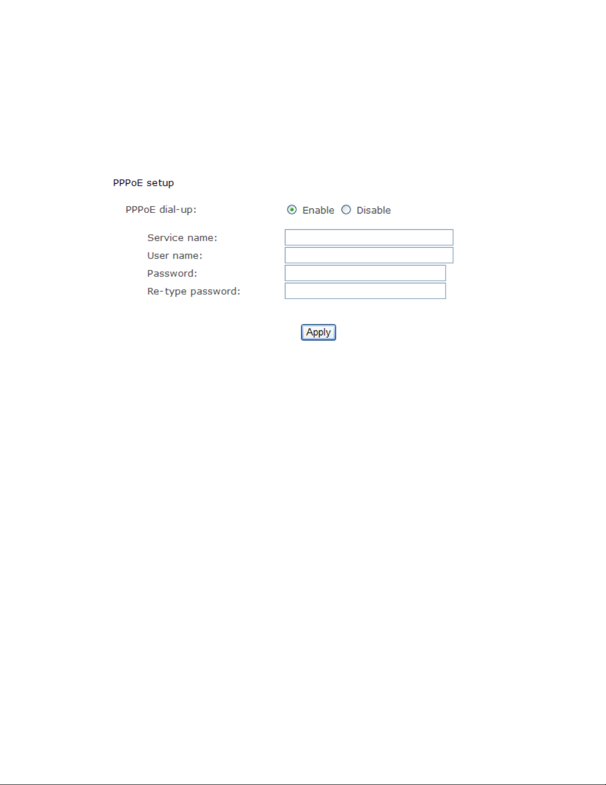
PPPoE Setup
The camera can be installed without a PC on the network. Some XDSL services use PPPoE
(Point-to-Point Protocol over Ethernet).
[PPPoE dial-up] Enable or disable PPPoE connection.
[Service name] Either an ISP name or a class of services that is configured on the PPPoE server. This field
may be left empty.
[User name] Type the user name.
[Password] Type the password.
[Re-type password] Re-confirm the password.
Click Apply to confirm your settings.
Page 39

39
DDNS Setup
Dynamic DNS (DDNS) is simply a way of using a static hostname to connect to a dynamic IP address.
When connected to your ISP, you are assigned a temporary IP address. DDNS services keep track of your
IP address and route your Domain name to that address when you wish to connect to the camera from a
remote location.
[DDNS] Enable or disable DDNS connection.
How to add DDNS
1. Enable the Dynamic DNS function.
2. Select your preferred DDNS service provider from the list then click Register.
3. Enter the Host Name details and password supplied by your DDNS service provider when you registered.
4. Click Apply to confirm your settings.
e.g.
Page 40

40
UPNP Setup
The camera supports UPnP which is enabled by default. This function requires a Windows XP/Vista
operating system. It is a quick way to discover the camera on your network. Please make sure that the
UPnP function is enabled on your PC.
[UPnP] Enable or disable the UPnP function.
[Gateway HTTP/RTSP port forwarding] Enable or disable this function.
[External HTTP/RTSP port range] Using this port, automatically adds a port forwarding rule to a router via
UPnP protocol. Please note that not all routers support this function. Refer to your router manual for further
details.
If set port range is 8150~8350, camera will ask router to add a port forwarding rule automatically. In this rule,
the internal port is camera default port 80, the external port is 8150, IP address is camera's IP. Use this
setting, users can visit the camera from Internet through the router with this URL
If there are several cameras in Local Network, the first one which first be opened will use 8150 as external
port, and second one will use 8151, third one use 8152, etc. Every camera will remember its port, it will
preferentially use this port in next power on.
[Gateway RTP port forwarding] Enable this function, users can use mobile phone , RealPlayer or
QuickTime Player to visit the camera from Internet through the router.
[External RTP port range] 30000—30200 default. (See TCP/IP setup)
Click Apply to confirm your setting.
Click System at the top right of Settings page to show the System information. See figure below.
http://routeripaddress:8150.
 Loading...