

Page 1
1
English
User's Manual
(Indoor, Infrared, Wire less Network Camera)
Firmware V0.95
Please read this manual car ef ul l y before you attempt to
Install this product and retain it for your future reference.
Page 2

2
Contents
MAIN FEATURES ............................................................................................................................................5
INSTALLATION ................................................................................................................................................8
NETWORK CAMERA INTERFACE & SETUP ............................................................................................... 13
Viewing the camera from your mobile phone ................................................................................................. 17
Network Camera Setting Interface ................................................................................................................. 18
Camera .......................................................................................................................................................... 20
Camera Setup ....................................................................................................................................... 20
Stream Setup ......................................................................................................................................... 21
How to use the URL stream list ............................................................................................................. 24
OSD Setup ............................................................................................................................................ 25
Night Vision Setup (IR IPCAM) .............................................................................................................. 26
Network .......................................................................................................................................................... 27
Wireless Setup ....................................................................................................................................... 27
TCP/IP Setup ......................................................................................................................................... 29
PPPoE Setup ......................................................................................................................................... 31
DDNS Setup .......................................................................................................................................... 32
UPNP Setup .......................................................................................................................................... 33
Alarm .............................................................................................................................................................. 36
Motion Detection .................................................................................................................................... 36
Schedule Setup ..................................................................................................................................... 38
Alarm Management ............................................................................................................................... 39
Periodic Sending .................................................................................................................................... 41
Buffer Management ............................................................................................................................... 43
Alarm Server .................................................................................................................................................. 44
FTP Server ............................................................................................................................................ 44
E-Mail Server
HTTP Server .......................................................................................................................................... 46
Storage .......................................................................................................................................................... 47
Storage setup ........................................................................................................................................ 47
Record on Alarm .................................................................................................................................... 48
Snapshot on Alarm ................................................................................................................................ 49
Continuous Record ................................................................................................................................ 50
Snapshot at Interval ............................................................................................................................... 51
FTP Sending .......................................................................................................................................... 52
Browse Storage ..................................................................................................................................... 53
Format SD Card ..................................................................................................................................... 54
Tools ............................................................................................................................................................... 55
System Identity ...................................................................................................................................... 55
User Management ................................................................................................................................. 56
Date & Time ........................................................................................................................................... 57
Backup or Reset .................................................................................................................................... 58
Firmware Upgrade ................................................................................................................................. 59
SPEEDREAD YOUR NETWORK CAMERA .................................................................................................. 60
Wizard ................................................................................................................................................... 60
System ................................................................................................................................................... 61
Support .................................................................................................................................................. 61
Reboot ................................................................................................................................................... 61
ADVANCED SETTINGS ................................................................................................................................ 62
Port Forwarding ..................................................................................................................................... 62
Proxy Server Setting .............................................................................................................................. 63
Reset the camera .................................................................................................................................. 64
DEFAULT SETTINGS .................................................................................................................................... 65
SPECIFICATIONS ......................................................................................................................................... 69
TROUBLESHOOTING ................................................................................................................................... 70
GLOSSARY OF TERMS
......................................................................................................................................... 45
................................................................................................................................ 71
Page 3

3
INTRODUCTION
Thank you for your interest and support in our product and purchasing this wireless network camera. The
camera can be accessed remotely, and controlled from any PC/laptop over the Intranet or Internet via web
browser. The user-friendly installation procedure and intuitive web-bas ed interface offer easy integration with
your LAN environment or WiFi system. The camera also comes with a lot of useful alarm tool for notice user
any situation. We feel confident that you will be pleased with the quality and features of this product.
Notice
This product may cause interferences with other wireless equipment that operates at 2.4GHz ISM band.
Please turn off one of the equipments to eliminate the interference.
Product Assurance
This camera will emit electromagnetic wave, just like other wireless products, but its transmitting power is
less than other wireless products such as mobile phones. The 2.4GHz wireless camera meets wireless
frequency security standards and recommended indexes while working. These standards and indexes are
certificated by academic organization and represent the cogitative research of the scientific workers who
continuously explore an d annotate the involved fields. So we beli ev e that our products are safe for customers.
Approval Information
All our products meet the requirements of approval FCC or CE, and are granted the FCC or CE
certification. They are authorized to bear FCC or CE mark.
FCC
This equipment has been tested and found to comply with the limits for a Class B digital device, pursuant to
Part 15 of the FCC rules. These limits are designed to provide reasonable protection against harmful
interference in a residential installation. This equipment generates, uses and can radiate radio frequency
energy and, if not installed and used in accordance with the instructions, may cause harmful i nterference to
radio communications. However, there is no guarantee that interference will not occur in a particular
installation. If this equipment does cause harmful interference to radio or television reception, which can be
determined by turning the equipment off and on, the user is encouraged to try to correct the interference by
one or more of the following measures: -Reorient or relocate the receiving antenna. -Increase the separation
between the equipment and th e r e ceiv er. -C onnect the equip ment into an out let on a circuit differ ent fr om that
to which the receiver is connected. -Consult the dealer or an experienced radio/TV technician for help.
This device complies with Part 15 of the FCC Rules. Operation is subject to the following two conditions:
(1) This device may not cause harmful interference, and
(2) this device must accept any interference received, including interference that may cause undesired
operation Changes and modification not expressly approved by the manufacturer or registrant of this
equipment can void your authority to operate this equipment under Federal Communications Commissions
rules.
CE
This product complies with standards including Low Voltage Device Directive 73/23/EEC; EMC
Directive 89/336/EEC and R&TTE Directive 1999/5/EC. It passed the subject tests by the authority
concerned and is authorized to bear CE mark.
Restrictions
1. DO NOT use this produ ct to v iolate one's pr ivacy . M onitoring one's activities without consent is illegal and
this product is not designed and manufactur ed for such purpo se.
2. DO NOT put this product near any medical equipment. Radio waves might potentially cause breakdown
of electrical medical equipment.
3. This product should be placed at least 1 foot away from any heart pacemaker. Radi o waves might
Page 4

4
potentially influence heart pacemaker.
4. DO NOT use this product for any illegal activities. It is the user’s responsibility to ensure that the
usage of this camera is of a legal nature.
Maintenance
1. Ensure that the camera and its power source have sufficient ventilation;
2. Do not shake, strike or drop the product;
3. Keep the camera dry and dustless and avoid exposing it to direct sunlight;
4. Do not place the produc t near any magnetic objects;
5. Avoid putting the product in places where there is constant temperature and humidity change;
6. Keep the product away from heat sources;
7. Do not use the camera near aggressive chemicals ;
8. Do not use this camera near water;
9. Do not use the camera in the places which are enclosed by metal . The surrounding metal may shield the
electromagnetic waves, and result in failure of signal reception;
10. Please obey the local government's environment protection policy;
11. Please turn off the power when left unused;
12. Do not disassemble or attempt to repair the camera; doing so might cause damage to the product.
Page 5

5
MAIN FEATURES
Easy Installation
The camera comes with built-in Wireless (IEEE802.11b/g/n) capability and a Web Server, therefore
there is no need to install a driver. The setup CD-ROM includes the Camera Setup software, User
Manual and Quick Installation Guide.
With ind ustry standard automatic configuration-UPnP (Universal Plug and Play), your PC will discover and
connect to your camera automatically. Once connected, using a simple Web browser you can see what the
camera sees from anywhere in the world!
The camera can be either wall-mounted or ceiling-mounted using the supplied stand. It can also be
placed on a desktop using the supplied stand, thus providing a flexi ble installation solution.
Up to1x faster than last processor
The new processor will bring you into better user’s experience, whether handling multi-client access from
different places or processes multita sk like motio n detec tion aler t and ons ite recording.
More memory, more features
With this memory expanding, we will be able to integrate more features for different purposes, and make the
product better competitive in the market.
Multi-stream & multi-video codec
In this new platform, different types of stream with different codec combinations for modern device like
iPhone, ipad & android system.
H.264 Compression
The latest H.264 compression technology allows the camera to lower bandwidth transmission, but with good
quality video. And maximum frame rate up to 30fps per second.
G.726, AMR & AAC Audio Compression
Many browsers support different types of audio format, our system has G.726, AMR & AAC audio format,
which covers all the web browser need.
802.11b/g/n Wireless LAN Connection Available
The new 802.11n Wireless LAN will enable data transmission rates up to 150M bit/s. and it’s utilizes
encryption methods such as WEP, and more power ful WPA and WPA2, so you can be sure your camera will
only be accessed by authorized users.
3GPP Mobile Surveillance
The camera provides the ability to view the cameras monitored through your mobile phone as a live video
stream, it supports the telecommunications standard of 3GPP streaming format. All 3G enabled mobile
devices and most 2G phones that support the streaming standard of 3GPP are compatible.
Simultaneous High-Speed H.264, MPEG-4 and Motion JPEG
The camera allows live the H.264, MPEG-4 and Motion JPEG streams simultaneously. The camera features
H.264, MPEG4 compression which compresses the video to make transmission faster and more efficient.
The H.264, MPEG4 and MJ PEG image can be transmitted at 30 frames per second.
Page 6

6
Simultaneous HTTP and RTSP streaming
The camera support HTTP and RTSP/RTP/RTCP protocol, and provide multiple HTTP and RTSP streams
simultaneously.
Audio Transmission
The camera comes with a built-in microphone for audio monitoring as well as video monitoring. Sound
captured by the camera is transmitted to the client’s PC.
Snapshot and Recording
You can capture a still image of the camera view on your PC and save the image as JPG or BMP format file.
You also can record the video and au dio captured by the camera on y our PC and save a s an A SF f orm at fi le.
Motion Detection Function
The camera can dete ct cha ng es in the image being monit or ed. Once a cha nge occur s it w ill send an ema il to
up to 3 email addresses with a video file or snapshot attached. The video file or snapshot can also be
uploaded to an FTP server. In addition the camera can be configured to send images at regular intervals.
OSD Function
OSD (On Screen Display) function can display system name, date and time, and user-defined on
screen.
Authentication
An authentication window requires you to enter the user ID and password. Password security can
prevent unregistered users from accessing your camera. Users can select Basic Authentication method
or Digest Access Authentication method.
Multi-Client Access
The camera allows up to 16 users to view the video simultaneously. Please note that it is possible that as the
number of simultaneously connected users to camera increases, the overall motion performance will
decrease.
Infrared Night Vision (IR IPCAM)
The camera utilizes 30 infrared LED to provide high light in darks environm ent. When the envir onment is dark,
the LED will be opened automatically due to a photosensitive component, and the moving images will be
changed to Black and White. Users can monitor clearly the things within 12 meters distance. Users also can
select open or close the infrared LED manually, and select whether change the images to black and white or
color automatically.
Page 7

7
Adapter
This product conforms with the authenticated AC adapter. The adapter is marked with one or more of the
following:
Note: When using the power adapter, make sure the rating v oltag e on it is compatible with t hat of the dev ic e
to avoid potential damages resulting from incorr ect usage of pow er supp ly.
PC System Requirements
The PC (Personal Computer) and the network must meet the following technical specifications for camera to
work properly.
1. Processor: Intel Pentium III, 1GHz or Higher (Pentium IV, 2 GHz or Higher
recommended)
2. RAM: 256 MB or more
3. Color Monitor: Suggest at least 800x600 and the latest driver for the Display Adapter
4. OS(Operating System): Windows 2000/XP/Vista
5. Web Browser: Internet Explorer Version 5.0 or above, DirectX 9.0c or later
6. Network Protocol: TCP/IP network protocol installed
7. Interface: 10/100 Mbps Ethernet® card/Wireless Network card for your network
connection
8. Other: CD-ROM Drive
Page 8
8
INSTALLATION
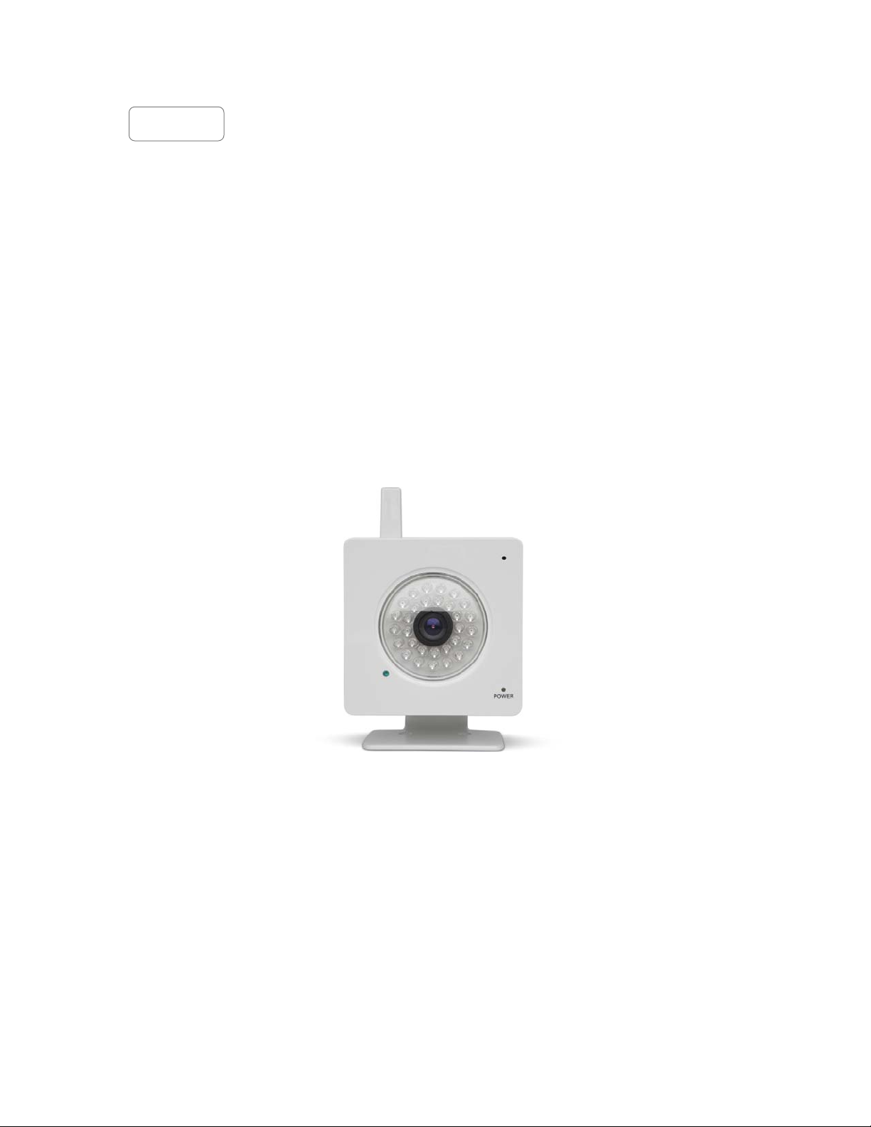
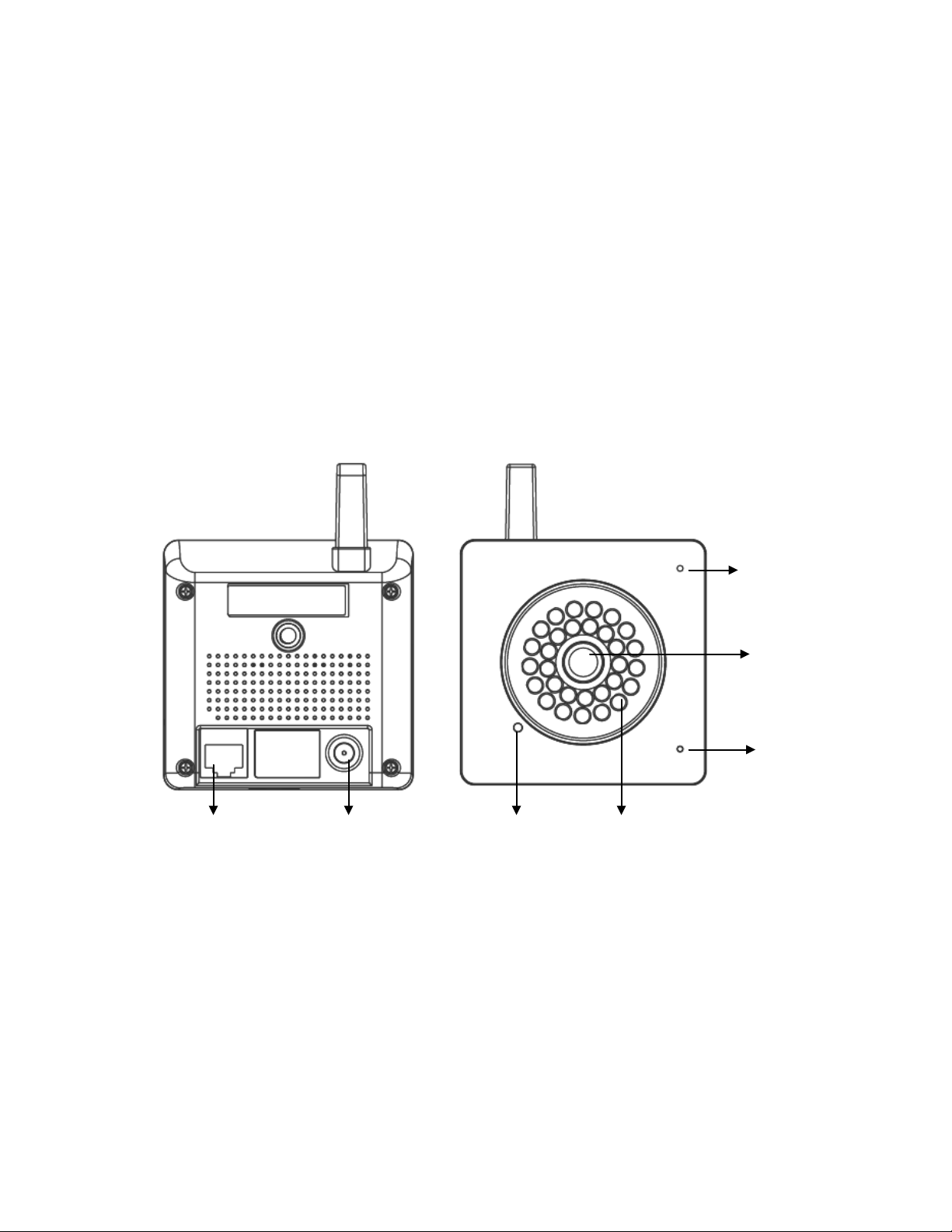
Power LED
Camera lens
Connecting the camera
Using a standard Ether net network cable, connect the camera to y our network (depending on your own setu p,
this may be to your router or switch). see figure below
Connect the included power adapter to the power port on the camera and the other end into an electrical
socket. see figure below
Check that the power indicator is lit on the front of the camera.
Note:
Please handle the power adapter carefully to avoid the risk of accidental electric shock.
Microphone
RJ45 slot power adapter slot light sensor infrared LED
Page 9
9
Camera Setup Installation & Usage
The camera Setup uti lity c an e asily a nd qu ic kly det ect ca meras connected to your local network and list th em
on the Camera Setup window, also you can use the camera Setup utility to assign an IP address to each
camera.
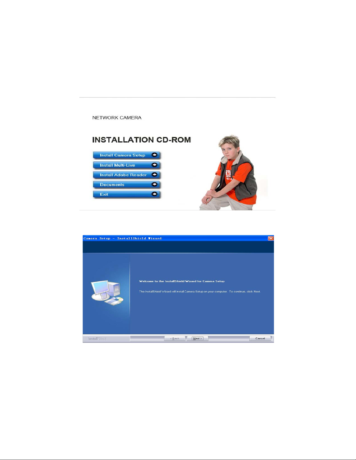
1. Insert the Installation CD into your CD-ROM drive and the installation screen should appear automatically
(See image below). If it does not, click “Start” then “Run”. In the text field enter “D:\autorun.exe” (if “D:” is the
letter of your CD-ROM Drive)
2. Click on “Install Camera Setup” and the following screen will be displayed.
3. If you want to change the default folder click “Change” to replace otherwise click “Next”
Page 10
10
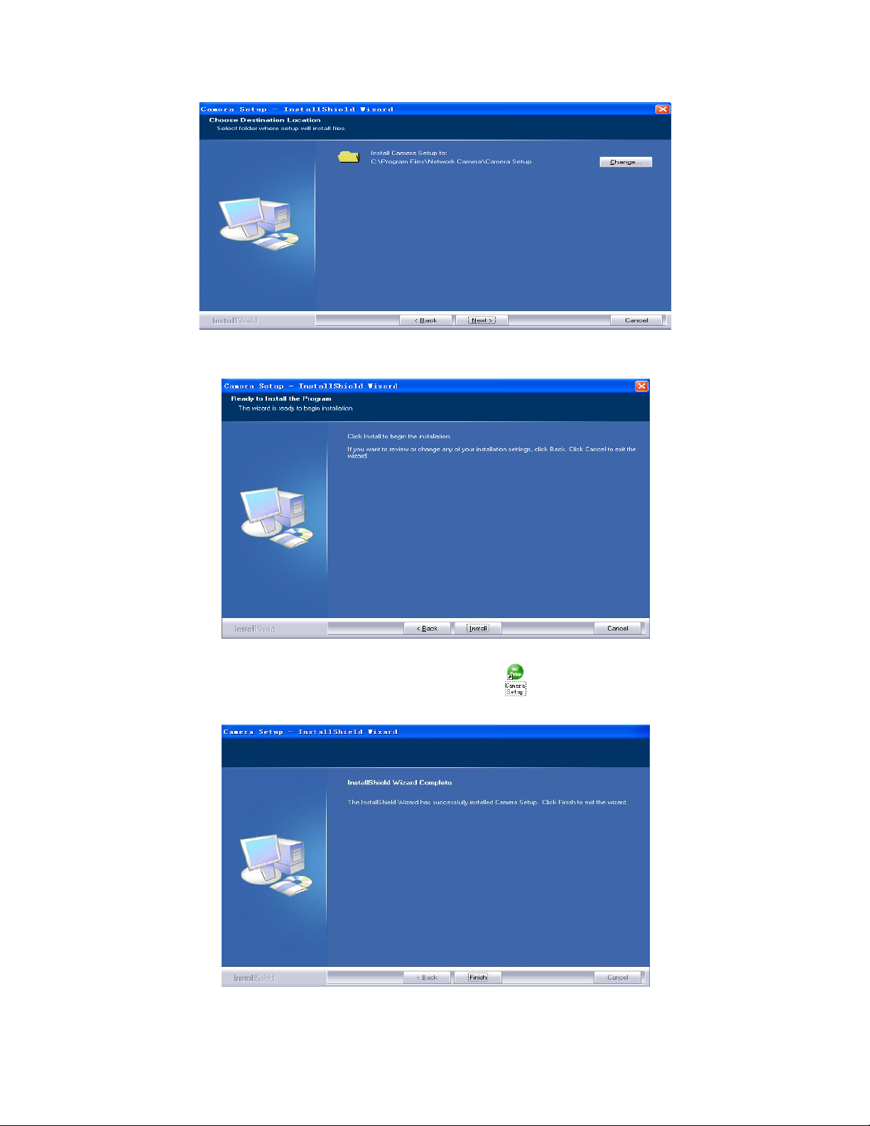
4. Click Install to install Camera Setup.
5. Click Finish to end the installation. You should now find a icon on the desktop.
Page 11

11
6. Double-click the Camera Setup icon on the Desktop to launch the program. The Camera Setup utility
should automatically find your camera if is correctly connected (See im age below) .
[Refresh] Click Refresh to search for cameras on the local network.
[Setup] Select the required camera and click Setup to configure the network settings for the camera.
[Open] Select the required camera and click Open to access the camera via a web browser.
[Exit] Click Exit to exit the Camera Setup window.
Note: Select and double click one of the cameras from the Device list, to open the camera view via the web
browser.
Assigning an IP address to the Camera with Camera Setup
1. Launch Camera Setup program to detect cameras on the local network.
2. Click on “Setup” button and the following setup interface will pop up.
Page 12

12
3. Enter a unique name for the camera, the location (optional) and leave the default port number as
80.“Obtain an IP address automatically” and “Obtain DNS server address automatically” are selected by
default, if you are confident enough to enter your own settings, you can do so by selecting “Use the following
IP address” and follow the guidelines on the next page. If however you wish to leave the default settings
please skip to NETWORK CAMERA SCREEN AND SETUP WINDOW.
4. To obtain the IP addresses specific to your network, click “Start” then “Run” and type “cmd” in the text box
and click “Ok”. The will bring up the MS-DOS prompt and in this window type “ipconfig/all” and press enter. A
screen similar to the one below will be displayed.
5. Take note of the following:
i) IP Address
ii) Subnet Mask
iii) Default Gateway
iv) DNS Servers (Both num bers with the first being the primary DNS server and the second being
the secondary DNS server)
6. Enter the details noted in step 5 into the relevant fields.
Note: The default IP address of the camera is 192.168.168.100This can be changed to any IP address on
your IP range. For example if the IP address of your PC is 192.198.1.52 then the IP address of your camera
should be unique and on the same subnet, i.e. 192.198.1.X where X is any number between 1 and 255
except 52. Ensure the IP address you chose is not the same as other network devices on your network as
this will result in conflict and may cause the device to not to work properly.
7. Once you’ve entered all the details click “Apply” then “Exit”.
Page 13

13
NETWORK CAMERA INTERFACE & SETUP
Review Images from the Network Camera
You can select one of the three ways to review pictures from the camera.
1. Input the assigned IP address (or URL) of the camera on the Web Browser. Take 192.168. 168.100 as
example. You will see the home page.
Notes:
Through this welcome page, you could choose to click on the item Enter to access the picture viewing
interface or the item Setting to access the system setti ng interface. The below dialog will appear. Input the
correct username (the default is admin, in lowercase) and password (the default is admin, in lowercase).
You are allowed to enter the picture viewing interface or the system setting interface.
The general users assigned by the administrator are not allowed to enter the system setting interface. They
can only be permitted to enter the picture viewing interface.
Page 14

14
2. If your OS is Windows XP, click [My Network Places], double click the icon
You will see the home page.
3. Run the Camera Setup and double-click the relevant camera item.
Page 15

15
Click Enter , you will see the screen as below.
to start sending audio from your computer’s
is automatically assigned the data & time of the snapshot.
[Audio Upload]
Press and release
microphone to the camera speakers.
Press and release to stop sending audio.
[Volume]
1. Click the Mute button to mute the audio.
2. Slide the Slide block horizontally to adjust volume.
[Snapshot]
1. Press the Snapshot button to capture a still image of the camera
view.
2. Press this button To change default Snapshot path, The file
Page 16

16
recording in seconds.
3. This button for Stream Type, Video Codec Settings.
[Record]
1. Press the Record button to record video and audio.
2. Recording Config. Click this button to set the recording
parameters, you can set record path, video file size and select whether to
start recording automatically when motion is detected and the length of the
[Tools]
1. For Full Screen mode click this button , Press Esc to exit.
It could also achieve same function by double click the Image Field.
2. For Fill up the Image field click this button .
Page 17

17
Viewing the came ra from your mobile phone
The camera provides the ability to view the cameras monitored through your mobile phone as a live video
stream, it supports the telecommunications standard of 3GPP streaming format. All 3G enabled mobile
devices and most 2G phones that support the streaming standard of 3GPP are compatible. Otherwise, you
also can view the pictures even if your phone is not 3GPP compatible.
For example, if camera’s external IP address is 202.96.135.206 and external port is 8151, then type
http://202.96.135.206:8151/mobile in your Internet browser address bar of mobile phone, the login screen
will appear:
To click the “Picture live” button if your mobile phone is not 3GPP standard, then you can view the pictures
which will refresh every 3 seconds.
To click the “3GPP stream live” if your mobile phone support 3GPP standard, and the following screen will
appear:
Note: You have to click “Setting” button, make sure that the Mobile stream is enabled and the RTSP
authentication is disabled before you view the 3GPP stream live.
Page 18

18
Network Camera Setting Interface
1. Click on settings from the home page. When connecting the camera for the first time or after res etti ng it to
its default settings, the set up i nter fa ce st art page below will load. It is recommend that you change the admin
password in order to avoid unauthorized access to the camera. To do this follow the instructions by clicking
on the underlined link “here” to access administrator password editing page.
2. Type the password in both fields then click Save. Please take note of the password. If you forget the
password, the camera will have to be reset to its default settings in order to gain access to the settings page
and this will also reset all other settings you may have changed.
Page 19

19
3. You are required to re-login with the changed password.
After successful login, the following page will appear.
Page 20

20
Camera
Camera Setup
From the home page click settings and enter the administrator user name and password. Click on Camera
Setup under the title Camera to change the image and audio parameters of the camera.
[Light frequency] Two options: 50Hz & 60Hz. Set ac cording to the mains frequency in the country of use.
For UK this would be 50Hz.
[Image mirror] Image can be flipped from left to right.
[Image flip vertical] Image can be flipped up and down.
[Moonlight mode] Turn On/OFF the brightness setting according to the light intensity of the area being
monitored manually. [Auto] automatic enhance ambient brightness when it is necessary.
[Power LED light] Turn on/off the power & network LED indicator of camera.
[Show FPS in ActiveX]Show FPS On/Off in ActiveX control.
[Microphone] Turn on/off the built-in microphone.
[Mic volume] Adjusts the volume of the microphone from 0~14 where 0 is the lowest.
[G.726 bit rate] pre-config the G.726 bit rate to determine the quality of the audio
[Audio bit rate] Four options: 16, 24, 32, 40(kbps). Determines the quality of the audio being transmitted.
[AMR bit rate] Eight options will Determines the quality of the audio being transmitted.
[Default audio codec] to choice default codec, when alarm triggers event to record on SD card or
somewhere else.
Click Apply to confirm your settings.
Note: If the camera is inversely installed, images flip horizontally and images flip vertically
should be turned on at the same t i me.
Page 21

21
Stream Setup
The camera supports three st r eams: primary stream, secondary stream and mobile stream.
Page 22

22
[Primary stream] cannot be disabled.
[Secondary stream] Enable or disable secondary stream.
[Mobile stream] Enable or disable Mobile stream.
You can use mobile phone, Realplayer and QuickTime Player to play the li ve stream from camera.
The size of video is 176x144.
Click Apply to confirm your setting.
[Image size] Three image resolutions available: 640 x 480(VGA), 320 x 240(QVGA), 160 x 120.
[Frame rate] Twelve options: 1/2/3/4/5/6/8/10/15/20/25/30 frames per second (fps).
[H.264 bit rate] select the bit rate for H.264, according your bandwidth.
[MPEG4 bit rate] Select MPEG4 bit rate.Eight options: 64, 128, 256, 512, 768, 1024, 1536, 2048 (kbps).
[MJPEG quality] Type MJPEG video quality. (20 – 100), 20 is low quality, 100 is high quality.
[Snapshot quality] Type snapshot quality. (20 – 100) , 20 is low quality, 100 is high quality.
The above five settings determine the image qual ity, however higher bit rates require greater bandwidth.
Please select the appropriate settings according to your connection speed and network traffic. If you are
experiencing jerky video it may be necessary to decrease the bit rate.
[Audio] Enable or disable audio.
[RTSP authentication] Enable or disable RTSP authentication.
You can use Mobile phone to play the mobile stream from camera, but generally Mobile phone do not
support authentication, s o we have to disable the RTSP authentication.
[Pre-Record Stream] is a streaming buffering to memory chips from live stream data. When alarm
triggered, the buffer stream will provide image data for a moment before the trigger starts. The
pre-record stream supported both HTTP & RTSP protocols with the URL list we provide.
[Depend on] to choice which pre-config stream from above to use on Pre-record stream.
[Pre-record time] allow you to set an accurate time to determine how many seconds stream data
should be saved before the alarm triggered.
Page 23

23
When you clicked the name of Primay stream, Secondary stream,
Mobile stream, the stream list will be open.
A sample of primary stream list as below:
[HTTP APPLE steam] M3u8 is an Apple HTTP Live streaming. It takes an MPEG-TS stream from a tool like
ffmpeg and breaks it up into multiple ts-segments.
You can use RealPlayer, VLC Player or QuickTime Player to play the live strea m from camera in
Intranet or Internet.
Page 24

24
How to use the URL stream list
http- stream.asf
http- stream1.asf
http- stream2.asf
Realplayer, support with sdp, asf stream
VLC player, support with sdp, asf,
The URL stream list helps
Primary stream
rtsp- live_h264.sdp
rtsp- live_mpeg4.sdp
rtsp- live_mjpeg.sdp
http- stream.m3u8
http- stream.jpg
Mobile stream Pre-record stream
rtsp- live_h264_3gpp.sdp
rtsp- live_3gpp.sdp
rtsp- live_amr_audio.sdp
rtsp- live_amr_audio.sdp
http- stream2.m3u8
http- audio_aac.m3u8
you to view the camera in
many ways.
You can put it into browser,
players, and web
application.
Combine with each stream
setting, like image size,
bandwidth, encode format.
You can easily manipulate
the video for different
purposes
Secondary stream
rtsp- live_h264_1.sdp
rtsp- live_mpeg4_1.sdp
rtsp- live_mjpeg1.sdp
http- stream1.m3u8
http- stream1.jpg
rtsp- pre_record.sdp
http- pre_record.m3u8
Combine with each strea m sett ing
Media player, support with asf stream
QuickTime, support with sdp stream
m3u8, jpg stream.
Page 25

25
OSD Setup
This function can display system name, date and time, or use-defined on screen.
[OSD] Enable or disable OSD function.
[Transparent] Users can select whether chan ge OSD to tra nspar ent or not.
[Display date and time] OSD is date and time of camera.
[Display system name] OSD is system name of camera.
[Display the text below] OSD is user-defined text.
[Display the text below with date and time] OSD is user-defined text with date and time of camera.
Click Apply to confirm your settings.
Page 26

26
Night Vision Setup (IR IPCAM)
Only IR IPCAM have infrared LED, which can be opened automatically when camera check dark
environment.
[Infrared LED control] When the environment is dark, the LED will be opened automatically due to a
photosensitive component. Users also can select open or close the infrared LED manually.
[Black and white mode] When the environment is dark, the moving images will be changed to Black and
White automatically. Users also can select whether change the images to black and white or color manually.
Click Apply to confirm your settings.
Page 27

27
Network
Wireless Setup
The camera corresponds to the wireless system based on IEEE802.11b/g. Encryption establishes the
security to prevent unauthorized users to access the wireless data communication.
[SSID] Type the ID of the wireles s network you want to connect to using up to 32 ASCⅡ characters or click
Search to search for available networks.
[Wireless] Enable or Disable the wireless function
[Mode] Infrastructure mode and Adhoc mode
Adhoc Mode: Select Adhoc mode when the camera is directly connected to your c omputer.
Infrastructure Mode: Select Infrastructure mode when the camera is connected via an access point or
router.
Page 28

28
When select Adhoc mode. See figure above.
[Security mode] WEP64bit or WEP 128bit
[Authentication] Select WEP authentication mode.
[WEP Key type] Select the WEP key type. Either in hexadecimal or ASCⅡ characters.
[WEP key Index] Specify up to 4 WEP keys.
[WEP Key] Type the password.
[Re-type WEP Key] Re-confirm the password.
When select Infrastructure mode. See figure above.
[Security mode] Security mode is not only WEP64bit or WEP128bit but also WPA-PSK or WPA2-PSK.
[Encryption type] TKIP and AES.
[WPA key]Type 8-63 characters as password.
[Re-type WPA key] Re-confirm the password.
Click Apply to save changes.
Click Test to test whether connection is successful.
Page 29

29
When click search ,see figure above.
[SSID] select the network name you searched .
[Mode] Infrastructure mode and Adhoc mode
[signal]It show out the strength of signal
[Encryption ] on and off.
Note: These settings have to match those of your access point or router. Please consult your access point or
router manual on how to verify or modify these settings.
TCP/IP Setup
The camera is set up to obtain the IP address automatically (DHCP) by default. Should you may wish to
assign the IP address manually, use the TCP/IP Setup page to enter the address details.
Obtain an IP address automatically (DHCP):
Page 30

30
If your network supports a DHCP server (e.g. router) select this option to have the IP address is assigned
automatically.
If you select Obtain an IP address automatically you should select Obtain a DNS Server address
automatically.
Use the following IP address:
Select this option when a fixed IP is required.
[IP address] Type the IP address of your camera.
[Subnet mask] Type the subnet mask.
[Default gateway] Type the default gateway.
Obtain DNS Server address automatically:
If your network supports a DHCP server (e.g. router) select this option to have the DNS Server address is
assigned automatically.
Use the following DNS server address:
[Primary DNS IP address] Type the IP address of the primary DNS server.
[Secondary DNS IP address] Type the IP address of the secondary DNS server, if necessary.
[HTTP/RTSP port]
The default HTTP port number is 80, it is also be used as RTSP port.
[RTP port range] It is for UPnP port forwarding, 1 camera actually use 2 RTP ports, one for video, the other
for audio. (See UPnP setup)
[HTTP/RTSP Authentication method] Select Basic Authentication or Digest Access Authentication.
Page 31

31
PPPoE Setup
The camera can be installed without a PC on the network. Some XDSL services use PPPoE
(Point-to-Point Protocol over Ethernet).
[PPPoE dial-up] Enable or disable PPPoE connection.
[Service name] Either an ISP name or a class of s ervices that is configured on the PPPoE server. This field
may be left empty.
[User name] Type the user name.
[Password] Type the password.
[Re-type password] Re-confirm the password.
Click Apply to confirm your settings.
Page 32

32
DDNS Setup
Dynamic DNS (DDNS) is simply a way of using a static hostname to connec t to a dynamic IP address. When
connected to your ISP, you are assigned a temporary IP address. DDNS services keep track of your IP
address and route your Domain name to that address when you wish to connect to the camera from a
remote location.
[DDNS] Enable or disable DDNS connection.
How to add DDNS
1. Enable the Dynamic DNS function.
2. Select your preferred DDNS service provider from the list then click Register.
3. Enter the Host Name details and password supplied by your DDNS service provider when you registered.
4. Click Apply to confirm your settings.
e.g.
Page 33

33
UPNP Setup
The camera supports UPnP which is enabled by default. This function requires a Windows XP/Vista
operating system. It is a quick way to discover the camera on your network. Please make sure that the UPnP
function is enabled on your PC.
[UPnP] Enable or disable the UPnP function.
[Gateway HTTP/RTSP port forwarding] Enable or disable this functio n.
[External HTTP/RTSP port range] Using this port, automatically adds a port forwarding rule to a router via
UPnP protocol. Please note that not all routers support this function. Refer to your router manual for further
details.
If set port range is 8150~8350, camera will ask router to add a port forwarding rule automatically. In this rule,
the internal port is camera default port 80, the external port is 8150, IP address is camera's IP. Use this
setting, users can visit the camera from Internet through the router with this URL
If there are several cameras in Local Network, the first one which first be opened will use 8150 as external
port, and second one will use 8151, third one use 8152, etc. Every camera will remember its port, it will
preferentially use this port in next power on.
[Gateway RTP port forwarding] Enable this function, users can use mobile phone , RealPlayer or
QuickTime Player to visit the camera from Internet through the router.
[External RTP port range] 30000—30200 default. (See TCP/IP setup)
Click Apply to confirm your setting.
http://routeripaddress:8150
.
 Loading...