

Page 1
ui
User's Manual
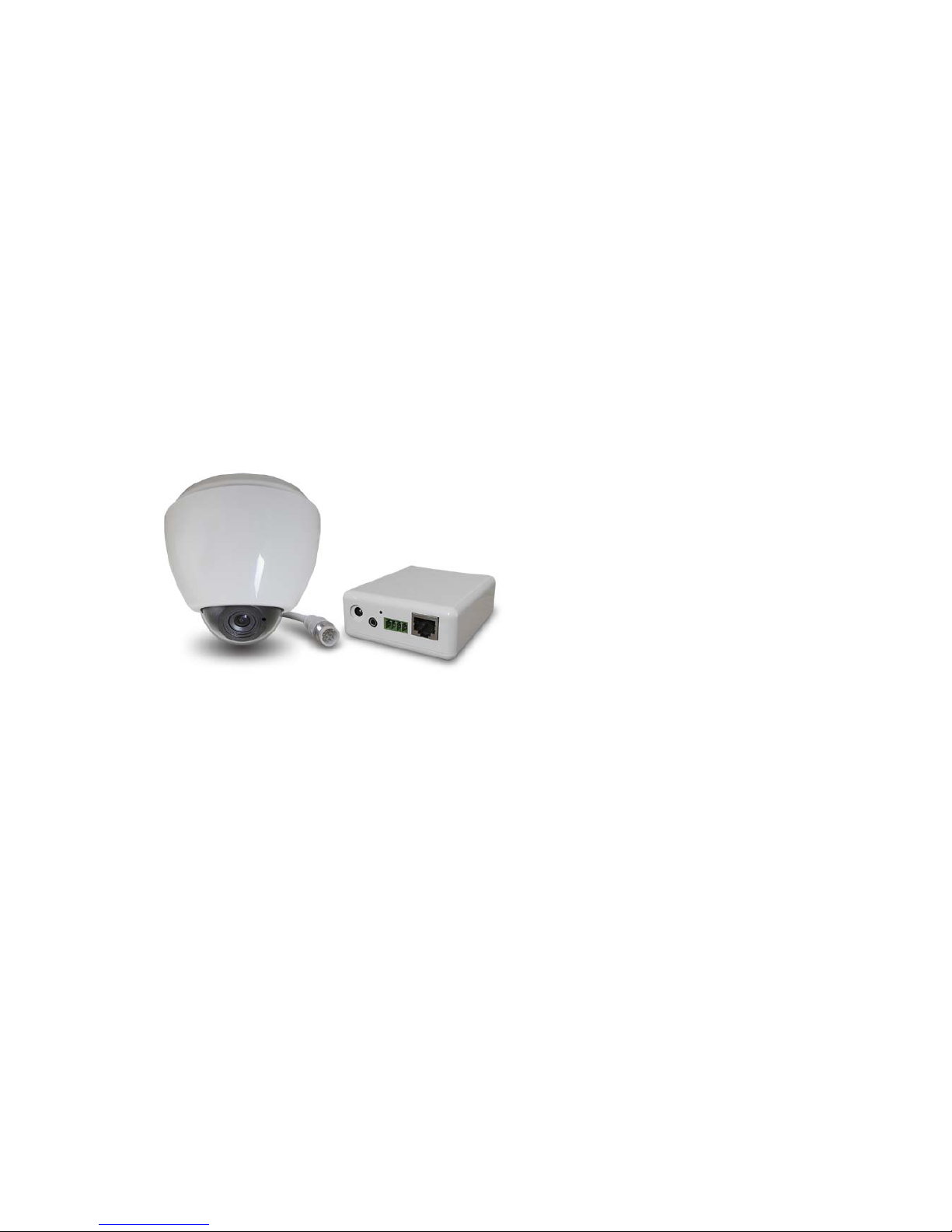
Dome IP Camera
V4.21
Please read this manual carefully before you
attempt to Install this product and retain it for your
future reference.
Page 2
9
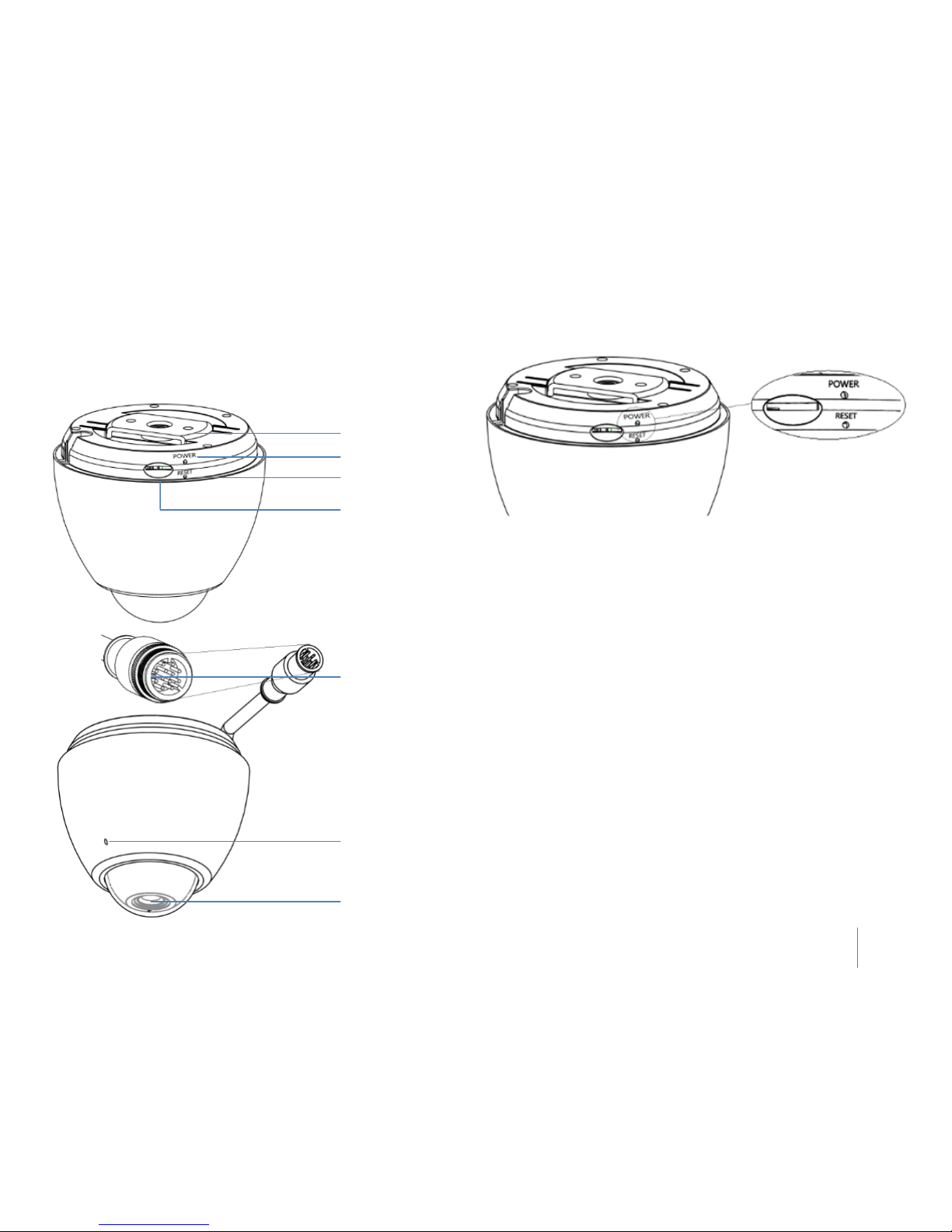
Physical Description
Dome IP Camera
Metal Mounting Kit
Status LED
Reset Button
SD Card Slot
Aviation Connect
Plug in
Built in
Microphone
LENS
Hardware Reboot & Restore
The Reset
button is used to restore the factory default settings.
Sometimes resetting the system can return the camera to normal
operation.
Restore - Press and release the reset button with a paper clip or thin
object. T
he LED light will be out, after few seconds it will relight again.
(Note: that all settings will be restored to factory default)
Status LED
The LED indicates the status of the Network Camera.
1) Green
LED - Power is being supplied to the Network Camera.
2) Blinking Orange LED –
IP camera has been connected and data is
present.
Page 3
10
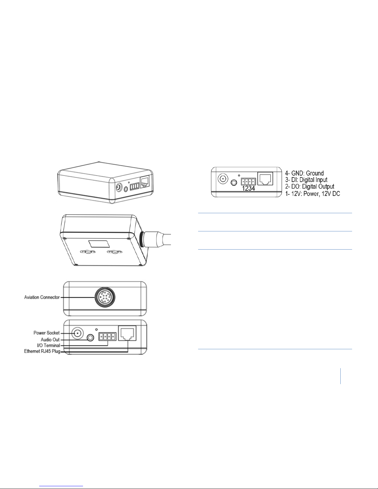
Adapter Box
General I/O Terminal Block
This Network Camera provides a general I/O terminal block which is
used to connect external input / output devices. The pin definitions
are described below.
Pin No. Name Function Description
4 GND Ground
This is a signal ground use for
DI and DO.
3 DI
Digital
Input
Connect to GND to activate or
deactivate by software setting.
2 DO
Digital
Output
With a maximum load of 1A
and maximum voltage of 60V
DV, this output has an
open-collector NPN Darlington
transistor with the emitter to
the GND pin.
If used with an external relay, a
diode must be
connected in
parallel with the load, for
protection against voltage
transients.
1 12V Power 12VDC ± 10%, max. 0.4A
Page 4
11
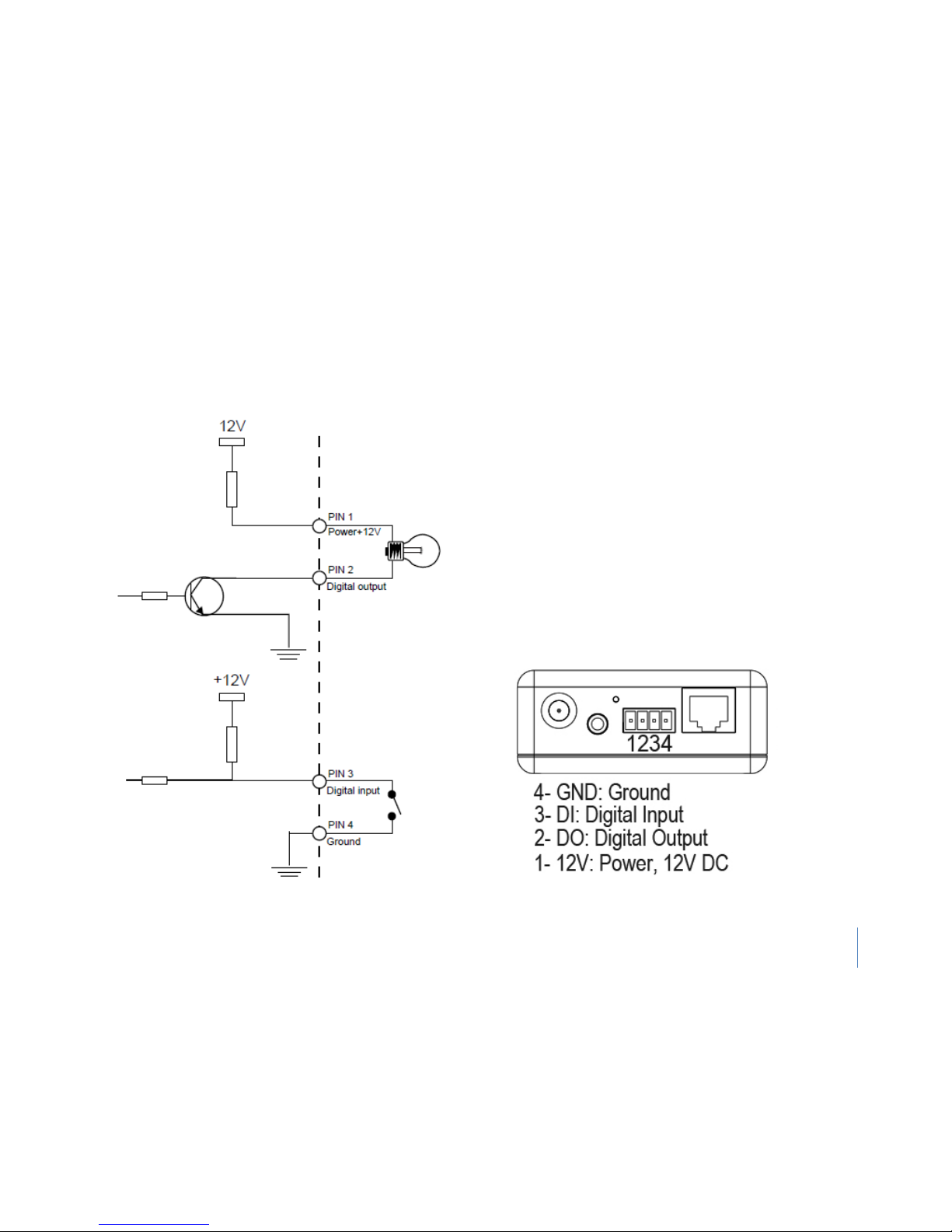
DI/DO Diagram
Please refer to the following illustration for the connection method.
Page 5
12
Installation Method
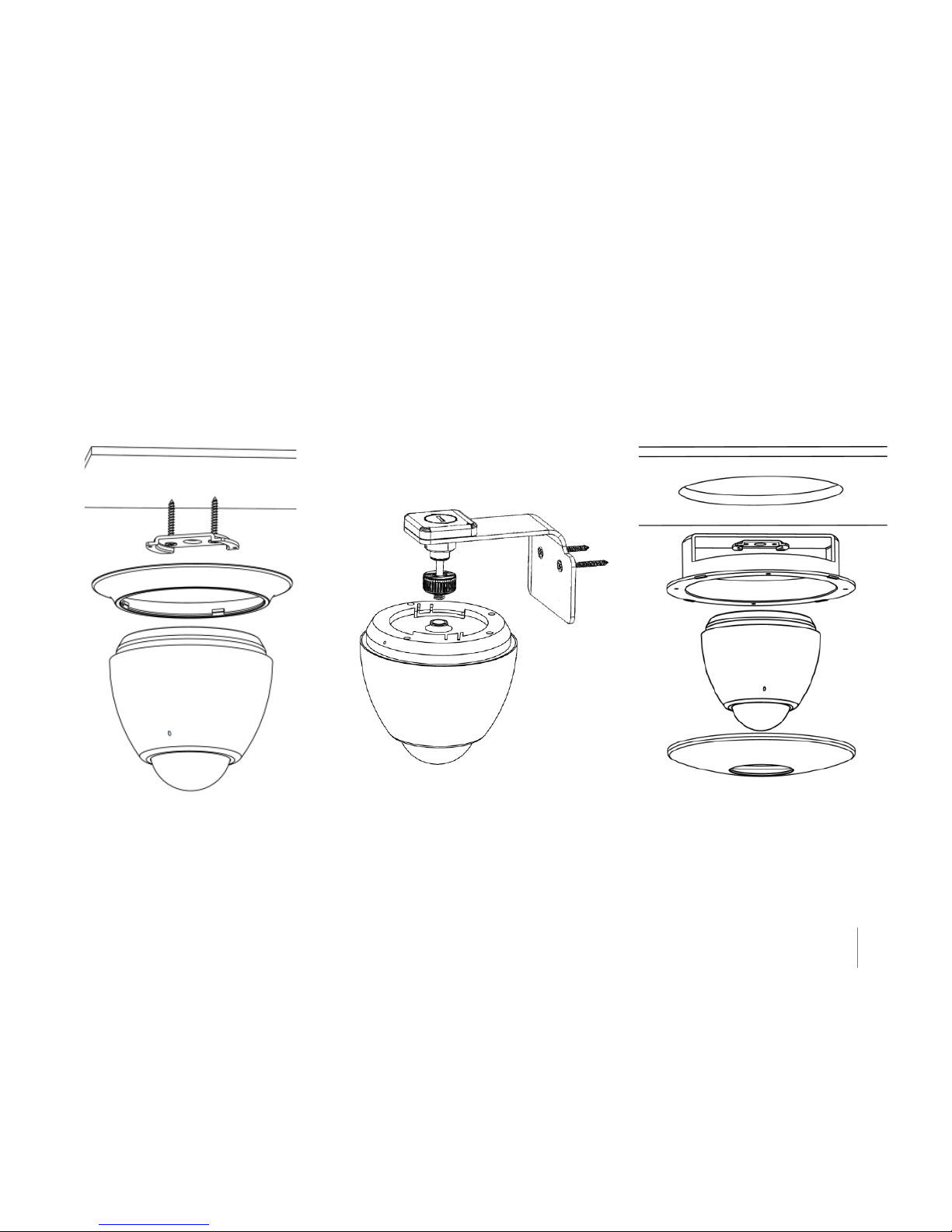
Please refer to the illustration and consider environment differences to appropriately mount the IP camera.
1)
2)
3)
Notes: This 2) 3) is extra mounting Kit and required to buy separately, please contact with
your dealer.
Page 6
13
Installation steps for metal bracket
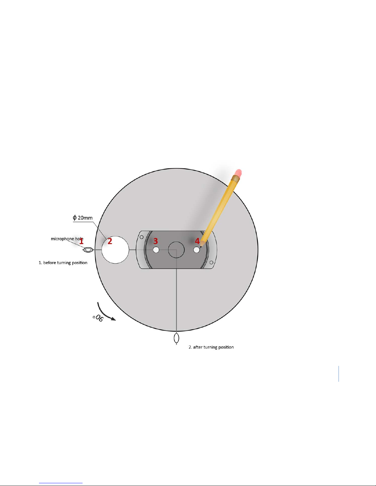
1) Take out the Installation Template (from the packing box), and stick it to the desired installation spot on your ceiling. Please mark down the 4
circles that show on the figure. (see picture below)
Page 7
14
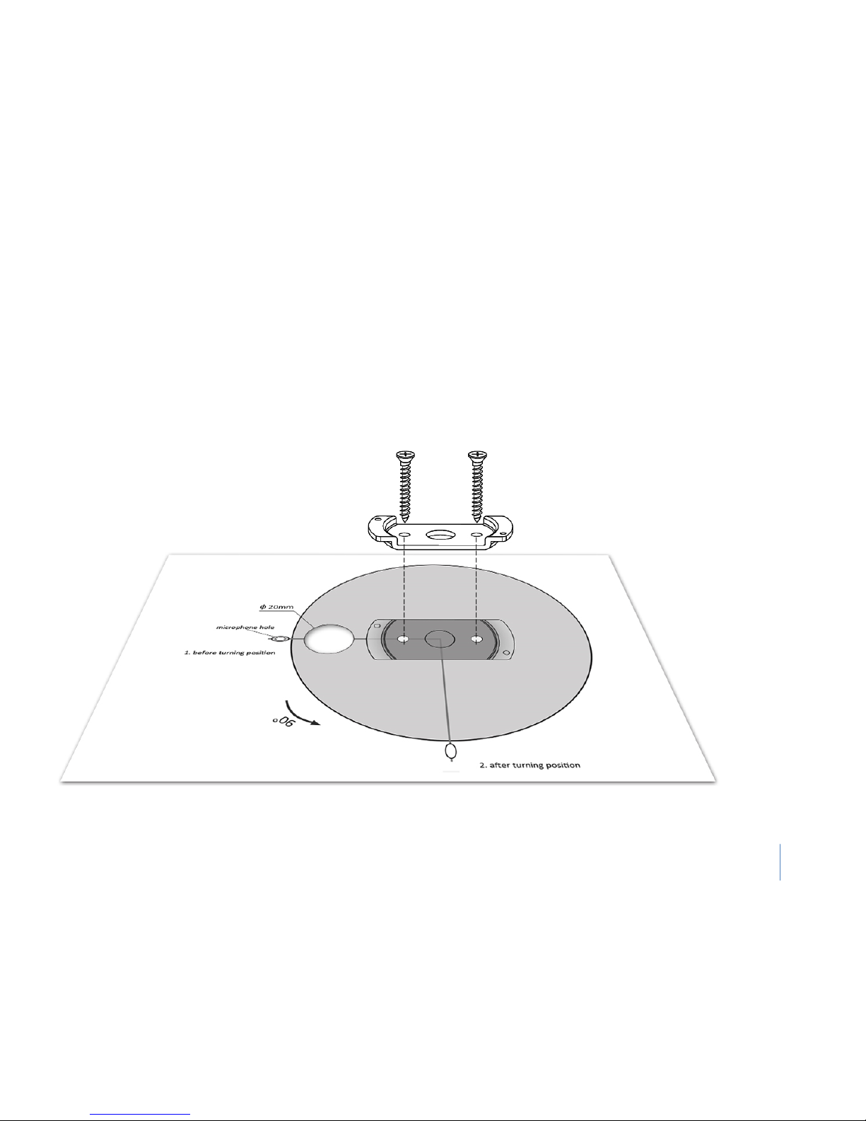
2) Screw down the metal bracket with the same position as the instruction figure, and drill the hole with at least 20mm diameter in specific
area.
Notes: this step is very important, and includes 2 key factors, 1. The centre line of the biggest circle should be on the same horizontal line as
the other circles. 2. The biggest circle should be between 20mm to 25mm in diameter.
Page 8
15
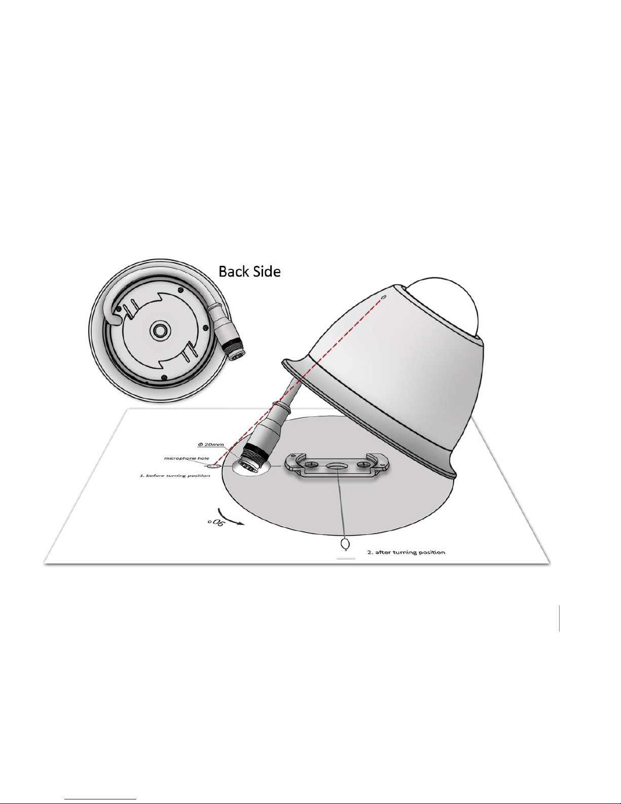
3) Before you try to attach the Dome IP camera to the ceiling, take off the white plastic chips (at cable outlet), then push the cable down into
the gap between camera and plastic ring ( see the picture below), then feed the cable connector into the biggest hole, and align the microphone
hole with the mark circle.
Page 9
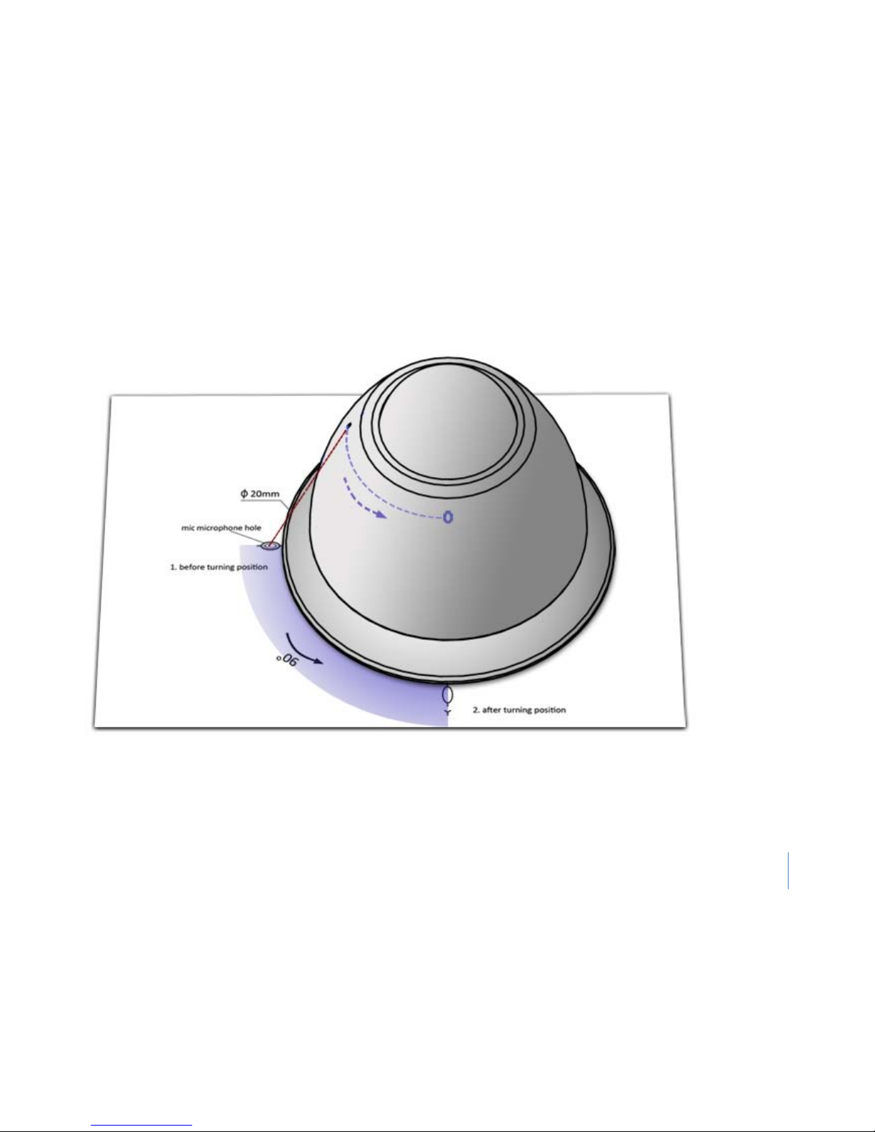
16
4) Turn the camera 90 degrees (anticlockwise), using the microphone hole as reference.
Page 10
17
Internet connection
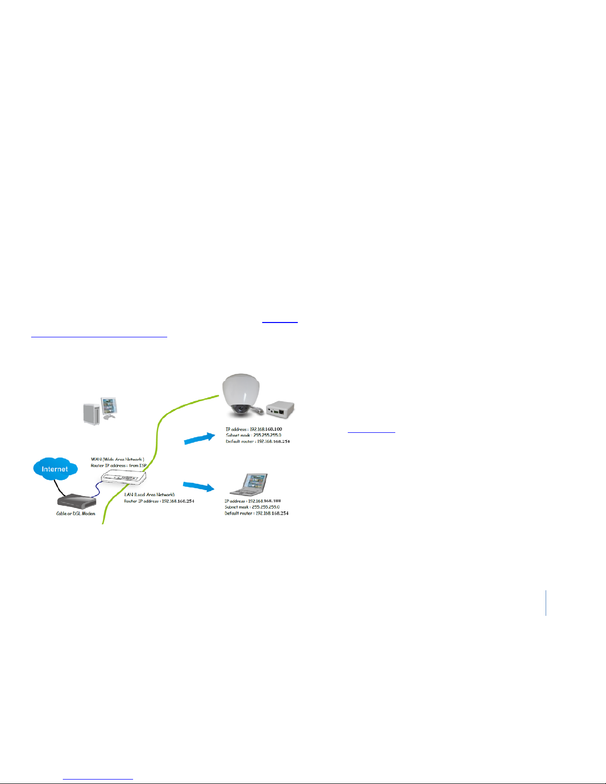
Connected Via a router
Before setting up the Network Camera over the Internet, make sure
you have a router and follow the steps below.
1) Connect
your Network Camera behind a router, the Internet
environment is illustrated below.
Regarding how to obtain your IP address, please refer to Manually
Setting TCP/IP Settings for a Camera for details.
2) In this case, if the Local Area Network (LAN) IP address of your
Network Camera is 192.168.168.100, please forward the following
ports for the Network Camera on the router.
HTTP port
RTSP port
RTP port for audio
RTCP port for audio
RTP port for video
RTCP port for video
If you have changed the port numbers on the Network page, please
open the ports accordingly on your router. For information on how
to forward ports on the router, please refer to your router’s user’s
manual.
3) Find out the public IP address of your router provided by your ISP
(Internet Service Provider). Use the public IP and the secondary
HTTP port to access the Network Camera from the Internet. Please
refer to
TCP/IP Setup for details.
Page 11

18
Connected directly to a Computer
You can also connect the IP Cam directly to a computer. Please note
that in this mode you will not be able to view your IP Cam from
anywhere else apart from the computer you are currently using.
Connect one end of the network cable in to the IP Cam Network
Connection socket, and plug the other end in to a spare network
port on your computer.
Connect the included power adapter to the power port on the
camera and the other end into an electrical socket. Do not turn the
power on at this time.
You must then assign your computer an IP address so it can talk
easily to the camera.
For Windows system:
1.
Open the Control Panel and double click on “Network
Connections” then right click on your “Local Ar
ea Network”
connection, and click Properties. Be sure to select the Network icon
that corresponds to where you have plugged the IP Cam in to – so
this would not be listed as a Wireless, WiFi or Bluetooth Network.
2. Select “Internet Protocol (TCP/IP)” then click Properties.
3.
Take note of your current TCP/IP Settings and then click on “Use
the following IP settings”
4. In the “IP Address” Field type in the number 192.168.168.20
5. In the “Subnet Mask” type in 255.255.255.0
6. Leave “Default Gateway” setting blank
(The camera will
automatically assign itself this IP address when no DHCP server is
present)
7. Leave DNS server settings blank.
8. Click “OK” then “Close” to apply these settings.
9. Turn the power on to the IP Cam.
The Connectivity Status indicator on the front of the camera will
light up.
Page 12
19
Viewing the camera from your mobile phone
The camera provides the ability to view the cameras monitored
through your mobile phone as a live video stream, it supports the
telecommunications standard of 3GPP streaming format. All 3G
enabled mobile devices and most 2G phones that support the
streaming standard of 3GPP are compatible. Otherwise, you also can
view the pictures even if your phone is not 3GPP compatible.
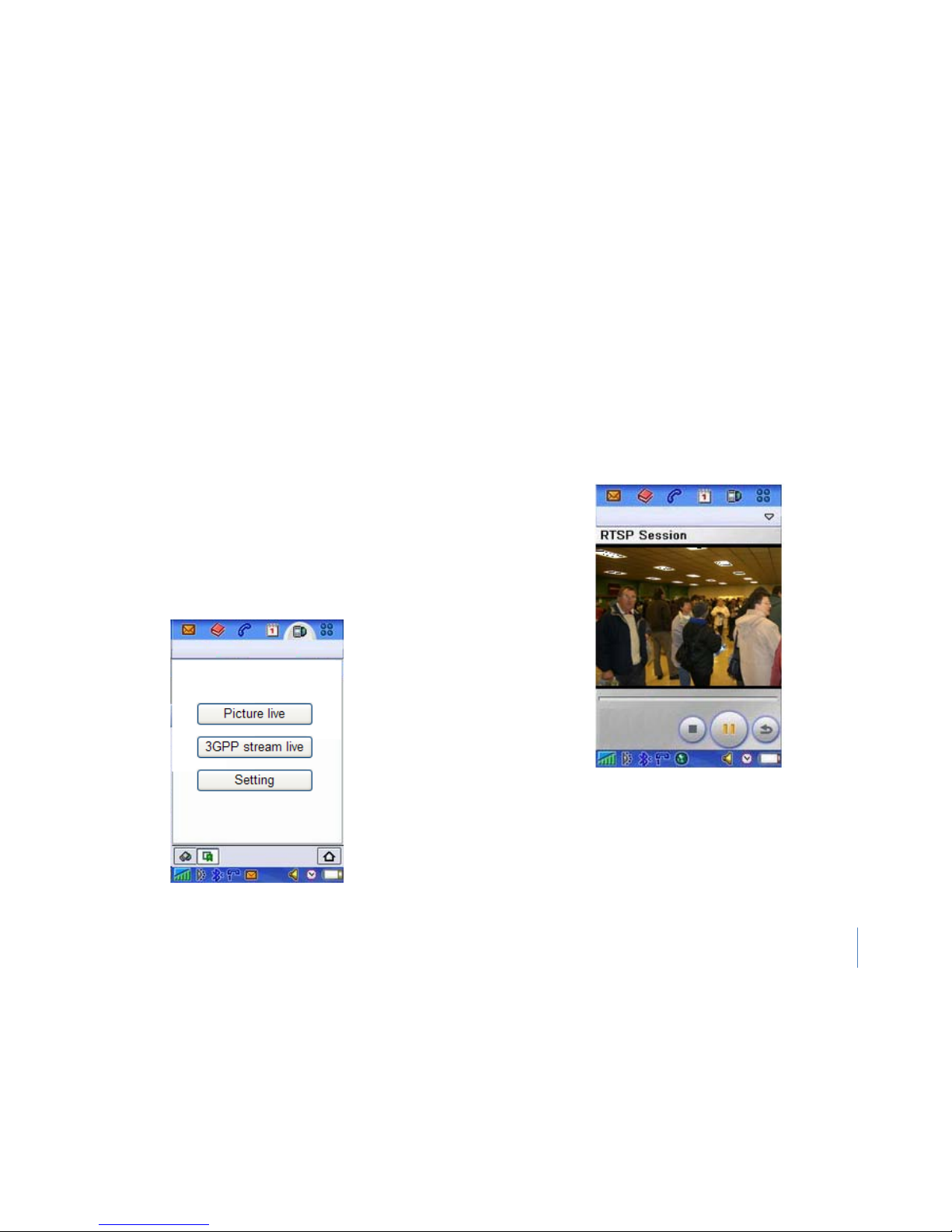
1) For example, if camera’s external IP address is 202.96.135.206 and
external port is 8151, then type http://202.96.135.206:8151/mobile
in your Internet browser address bar of mobile phone, the login
screen will appear:
2) To click the “Picture live” button if your mobile phone is not 3GPP
standard, then you can view the pictures which will refresh every 3
seconds.
3) To click the “3GPP stream live” if your mobile phone support 3GPP
standard, and the following screen will appear:
Notes: You have to click “Setting” button, make sure that the Mobile
stream is enabled and the RTSP authentication is disabled before you
view the 3GPP stream live.
Page 13
20
Manually Setting TCP/IP Settings for a Camera
In most cases, this is not required as the router will assign the correct
settings to the camera. It is however useful if you want to setup the
TCP/IP settings of the camera before you connect to it, if DHCP is
disabled across your network, or if you have subnet network
problems.
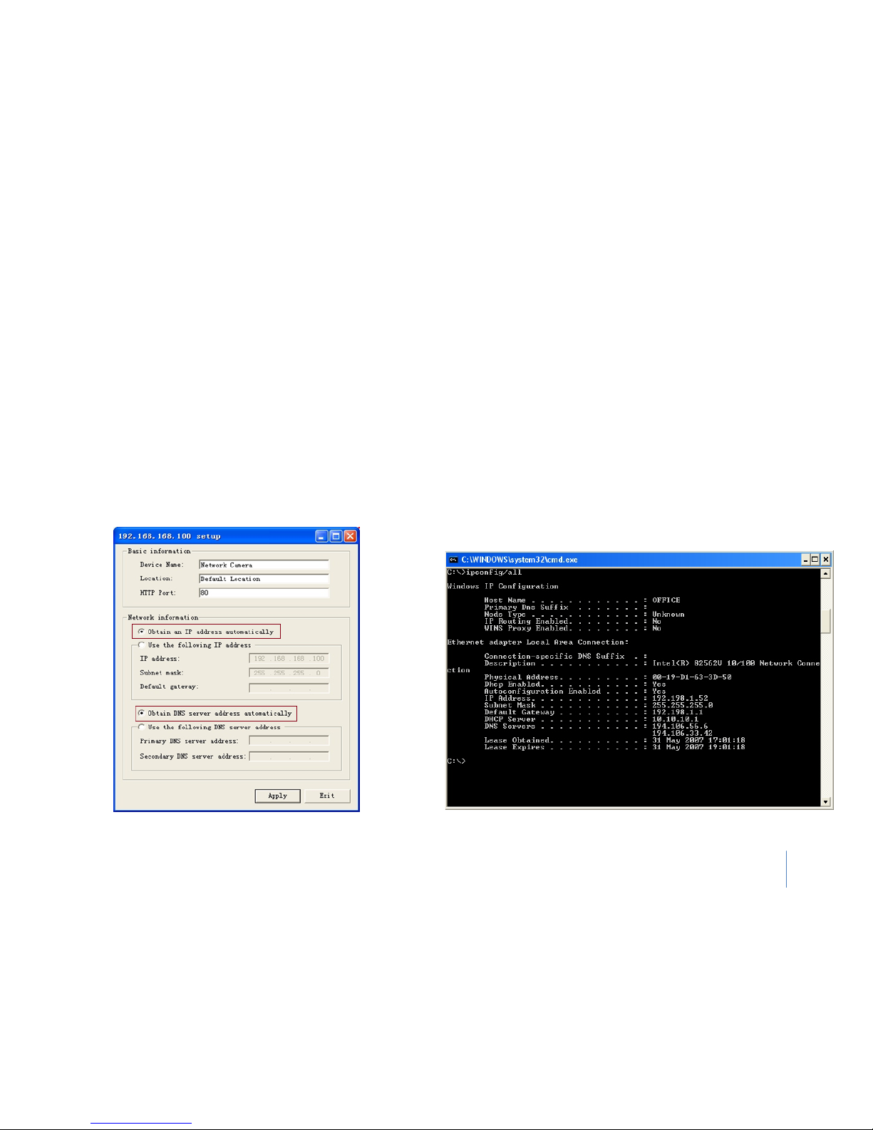
1) Launch Camera Setup program to detect cameras on the local
network.
2) Click on “Setup” button and the following setup interface will pop
up.
3)
Enter a unique name for the camera, the location (optional) and
leave the default port number as 80. “Obtain an IP address
automatically” and “Obtain DNS server address automatically” are
selected by default, if you are confident enough to enter your own
settings, you can do so by selecting “Use the following IP address” and
follow the guidelines on the next page.
4) To obtain the IP addresses specific to your network, click “Start”
then “Run” and type “cmd” in the text box and click “Ok”. The will
bring up the MS-DOS prompt and in this window type “ipconfig/all”
and press enter. A screen similar to the one below will be displayed.
Page 14

21
5) Take Notes of the following:
a. IP Address
b. Subnet Mask
c. Default Gateway
d. DNS Servers (Both numbers with the first being the primary DNS
server and the second being the secondary DNS server)
6) Enter the details Noted in step 5 into the relevant fields.
Notes: The default IP address of the camera is 192.168.168.100This
can be changed to any IP address on your IP range.
For example if the IP address of your PC is 192.198.1.52
then the IP address of your camera should be unique and on the
same subnet
i.e. 192.198.1.X where X is any number between 1 and 255 except
52
Ensure the IP address you chose is not the same as other network
devices on your network as this will result in conflict and may cause
the device to not to work properly.
7) Once you’ve entered the details click “Apply” then “Exit”.
Page 15
22
Program installation & Usage
The camera Setup utility can easily and quickly detect cameras
connected to your local network and list them on the Camera Setup
window; also you can use the camera Setup utility to assign an IP
address to each camera.
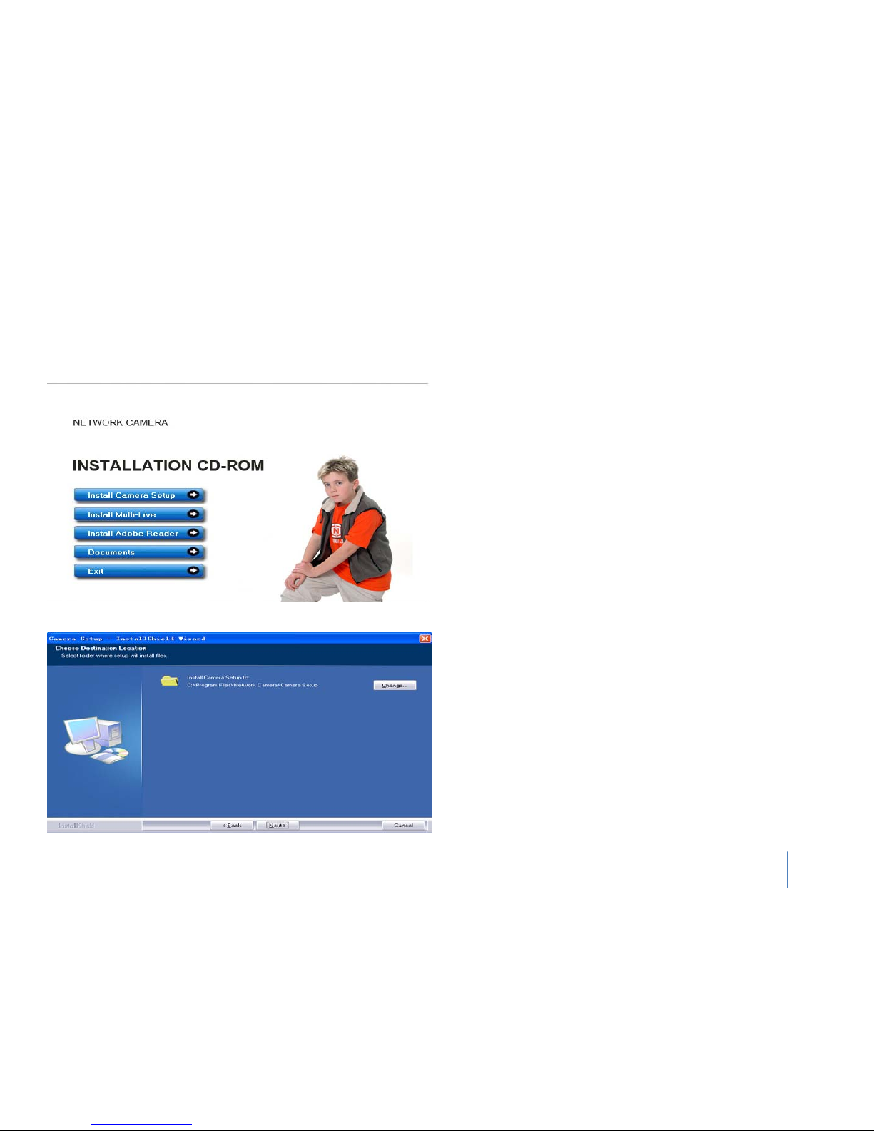
1) Insert the Installation CD into your CD-
ROM drive and the
installation screen should appear automatically (See image below). If
it does not, click “Start” then “Run”. In the text field enter
“D:\autorun.exe” (if “D:” is the letter of your CD-ROM Drive)
2) Click on “Install Camera Setup” and with the following screen Click
“Next”.
3) If you want to change the default folder click “Change” to replace
otherwise click “Next”.
4) Click “Install” to install IP Camera Software.
5) Click “Finish” to end the installation. You should now find an icon
on the desktop.
Page 16
23
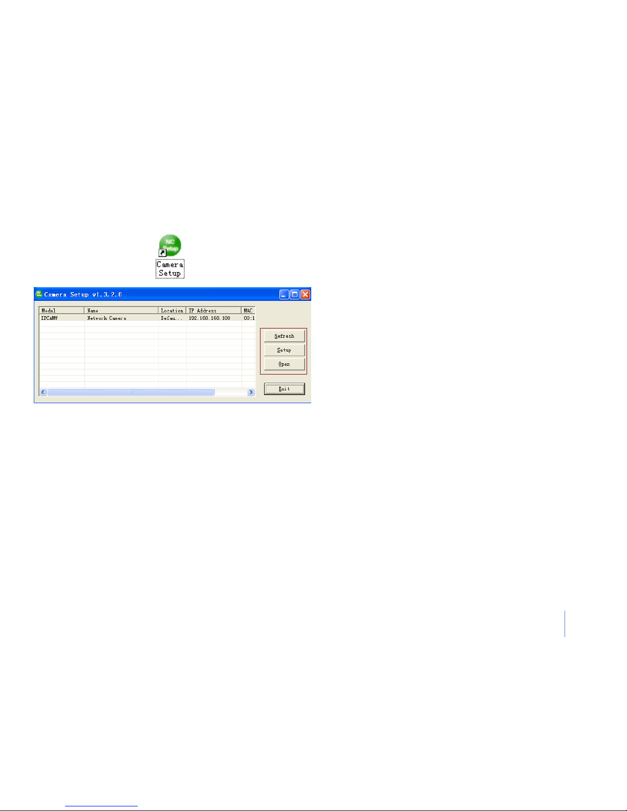
6) Double-click the Camera Setup icon on the Desktop to launch the
program. The Camera Setup utility should automatically find your
camera if is correctly connected (See image below).
Refresh - Click Refresh to search for cameras on the local network.
Setup - Select the required camera and click Setup to configure the
network settings for the camera.
Open - Select the required camera and click Open to access the
camera via a web browser.
Exit - Click Exit to exit the Camera Setup window.
Tips: Select and double click one of the cameras from the Device list, to
open the camera view via the web browser.
Page 17
24
Launch the Program
1) Find Icon from the desktop and double click it,
2) Find IP Camera from the pop up window
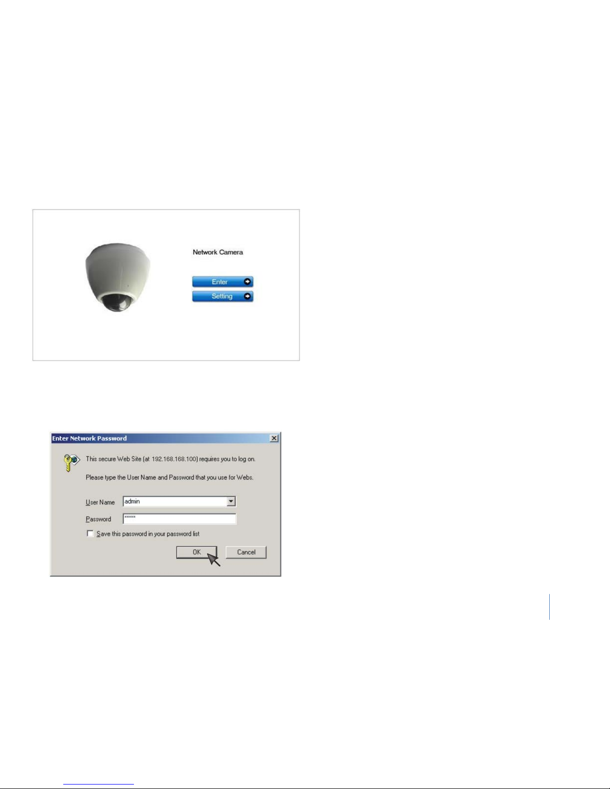
3) Double click the relevant IP Camera item or click “Open” button, the
IP camera homepage will shows up with your default Internet explorer.
Login in
You could choose to click on the item Enter to access the picture
viewing interface or the item Setting to access the system setting
interface.
The dialog will appear. The default username and password for IP
Camera is:
Username: admin
Password: admin
Tips: The general users assigned by the administrator are not allowed
to enter the system Setting interface. They can only be permitted to
Enter the picture viewing interface.
Page 18
25
User Interface
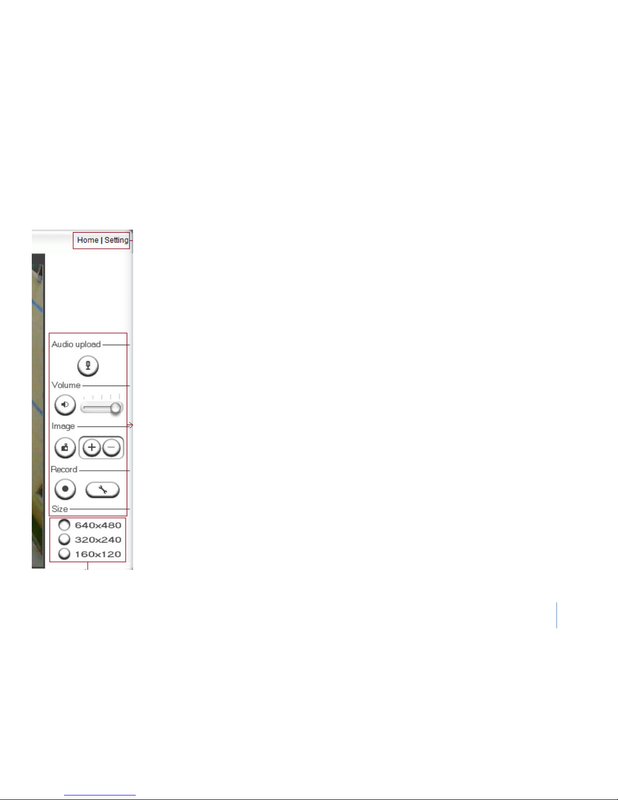
Home - takes you back to your Homepage.
Settings - will take you to the cameras internal settings.
Audio Upload - Press and release to start sending audio from your computer’s microphone to the camera
speakers.
Press and release to stop sending audio.
Volume----
Mute - Click the Mute button to mute the audio.
Slider - the slide block horizontally to adjust volume.
Image----
Snapshot -
Press the Snapshot button to capture a still image of the camera view. Click Save to store the
snapshot on your computer, the file is automatically assigned the data & time of the snapshot. Press Cancel to
exit.
Zoom - Click on the + button and the cursor turns to a magnifier. Move the magnifier to the desired location
and click on an image area. Press - button to return to the normal view.
Record-----
Recording - Press the Record button to record video and audio (if enabled). This will save the file in ASF
format on your PC.
Recording options -
Click this button to set the recoding parameters. You can set record path, video file size
and select whether to star recording automatically when motion is detected and the length of the recording in
seconds.
Size-----
Image size - There are three Image Size options: [640x480] [320x240] [160x120] Please Notes that this only
changes the image size being viewed not the image size the camera is transmitting and/or recording. To
change the transmitting/recording image size, please refer to the Stream Setup.
Page 19
26
Network Camera Interface Setting
Change the passwords
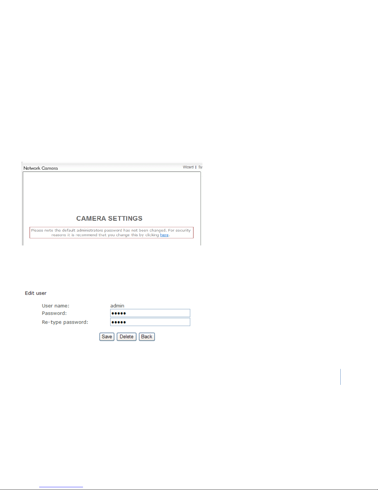
1) Click on Settings from the home page. When connecting the
camera for the first time or after resetting it to its default
settings, the setup interface start page below will load.
It is recommended that you change the admin password in
order to avoid unauthorized access to the camera. To do this
follow the instructions by clicking on the underlined link “here”
to access administrator password editing page.
2) Type the password in both fields then click Save. Please take
Notes of the password. If you forget the password, the camera
will have to be reset to its default settings in order to gain
access to the settings page and this will also reset all other
settings you may have changed.
Page 20
27
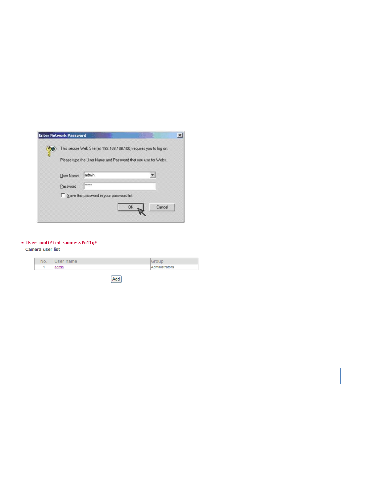
3) You are required to re-login with the changed password.
Notes: After successful login, the following page will appear.
Page 21
28
Camera
Camera Setup
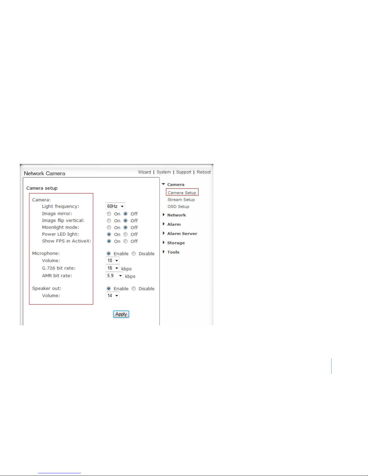
From the home page click settings and enter the administrator user name and
password.
Notes: If the camera is inversely installed, images flip horizontally and images flip
vertically should be turned on at the same time.
Camera:
Light frequency- Two options: 50Hz & 60Hz. Set
according to the mains frequency in the country of
use. For UK this would be 50Hz.
Image mirror- Image can be flipped from left to right.
Image flip vertical- Image can be flipped up and
down.
Moonlight mode- Turn On/off the brightness setting
according to the light intensity of the area being
monitored manually.
Power LED light- Turn on/off the power & network
LED indicator of camera.
Show FPS in ActiveX- Show FPS On/Off in ActiveX
control.
Microphone-Turn on/off the built-in microphone.
Volume- Adjusts the volume of the microphone from
0~14 where 0 is the lowest.
G.726 bit rate- Four options: 16, 24, 32, and 40(kbps).
Determines the quality of the audio being
transmitted.
AMR bit rate- Eight options will Determines the
quality of the audio being transmitted.
Speaker out – enable or disable speaker out function
Volume – control the Volume of the sound
Click Apply to confirm your settings.
Page 22
29
Camera
Stream Setup
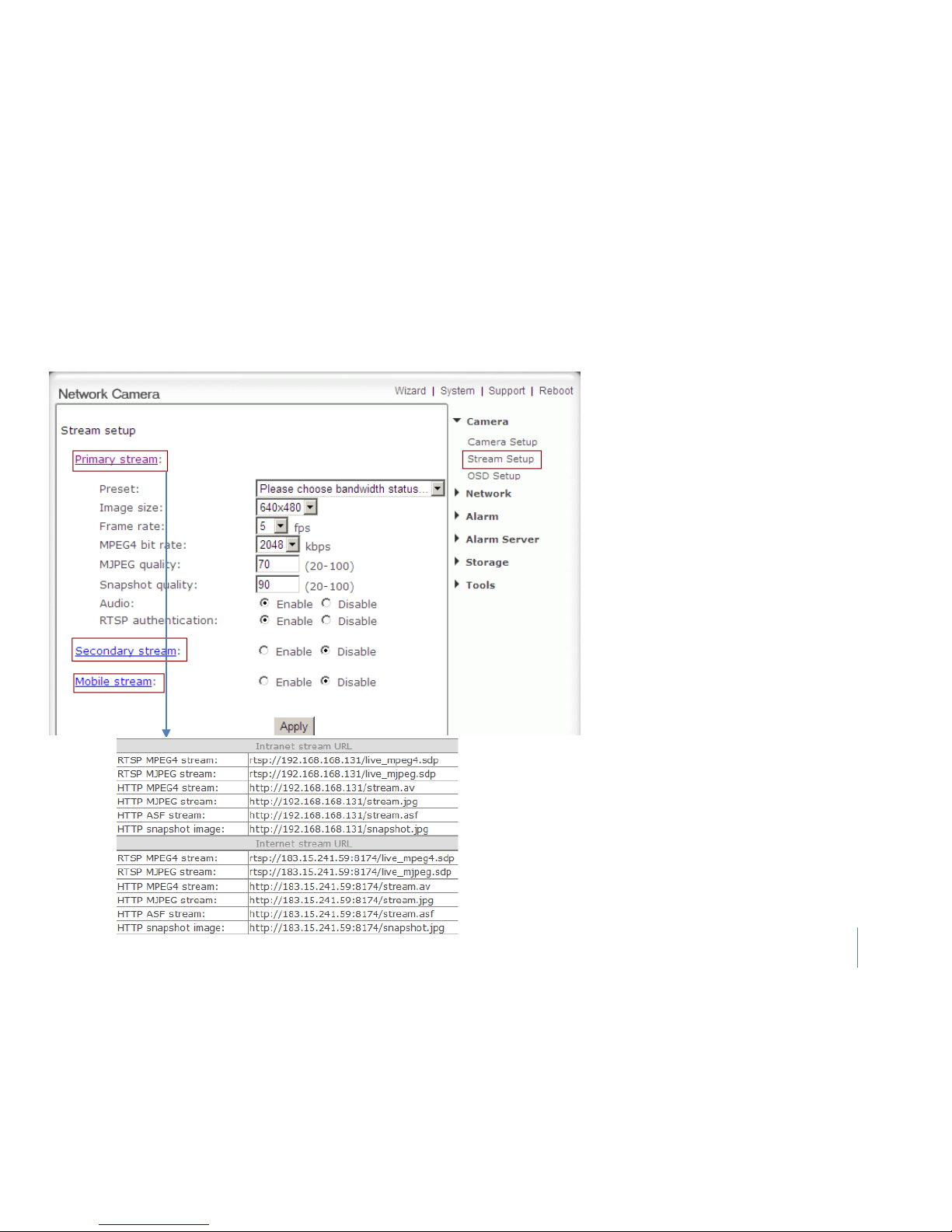
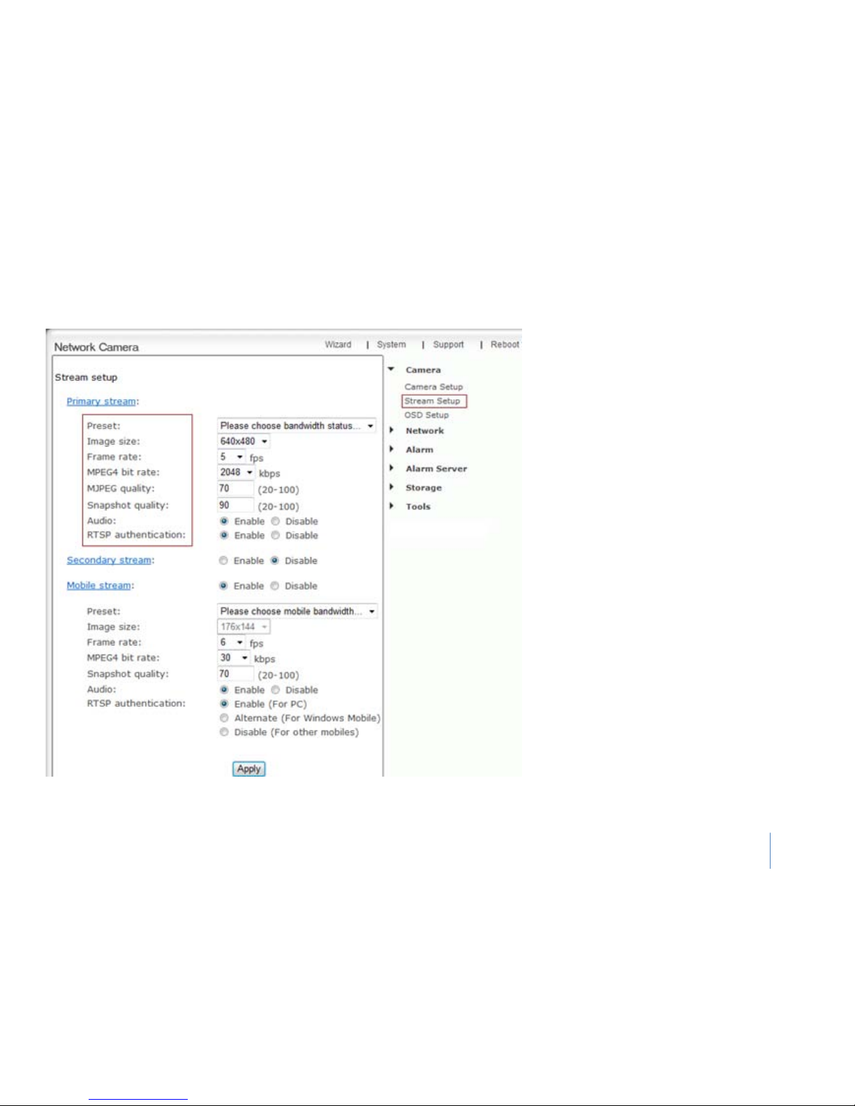
The camera supports three streams: Primary
stream, Secondary stream and Mobile stream.
Steam setup
Primary stream- cannot be disabled. You can
use RealPlayer, VLC Player or QuickTime Player
to play the live stream from camera in Intranet
or Internet.
Secondary stream- Enable or disable secondary
it
Mobile stream- You can use mobile phone,
RealPlayer and QuickTime Player to play the live
stream from camera. The size of video is 176 x
144.
A stream list page will be shown after clicking the
stream name such as “Primary stream”. A sample
of primary stream list as left:
Page 23
30
Camera Stream Setup (2)
Notes: Use Mobile
phone to play the mobile stream from camera, but generally Mobile
phone do not support authentication, so we have to disable the RTSP authentication.
Preset- choose bandwidth status at your place
Image size- Three image resolutions available:
640 x 480(VGA), 320 x 240(QVGA), 160 x 120.
Frame rate - Twelve options:
1/2/3/4/5/6/8/10/15/20/25/30 frames per
second (fps).
MPEG4 bit rate - Select MPEG4 bit rate. Eight
options: 64, 128, 256, 512, 768, 1024, 1536,
2048 (kbps).
MJPEG quality - Type in MJPEG video quality
value (20 – 100), 20 is low quality, 100 is high
quality.
Snapshot quality- Type snapshot quality. (20 –
100), 20 is low quality, 100 is high quality.
Audio- Enable or disable audio.
RTSP authentication- Enable or disable RTSP
authentication.
TIPS: The above five settings determine the image
quality, however higher bit rates require greater
bandwidth. Please select the appropriate settings
according to your connection speed and network
traffic. If you are experiencing jerky video it may be
necessary to decrease the bit rate.
Page 24
31
Camera
OSD Setup
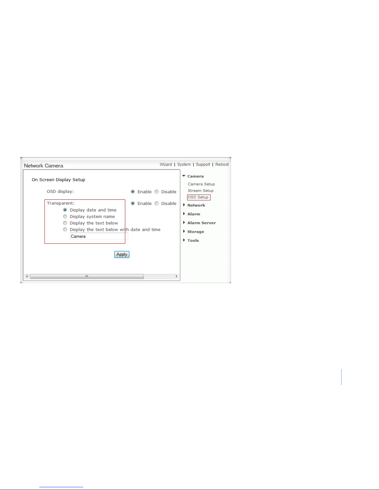
This function can display system name, date and
time, or use-defined on screen.
OSD display - Enable or disable OSD function.
Transparent - Users can select whether change
OSD to transparent or not.
Display date and time - OSD is date and time of
camera.
Display system name - OSD is system name of
camera.
Display the text below - OSD is user-defined
text.
Display the text below with date and time -
OSD is user-defined text with date and time of
camera.
Click Apply to confirm your settings.
Page 25
32
Network
Wireless Setup
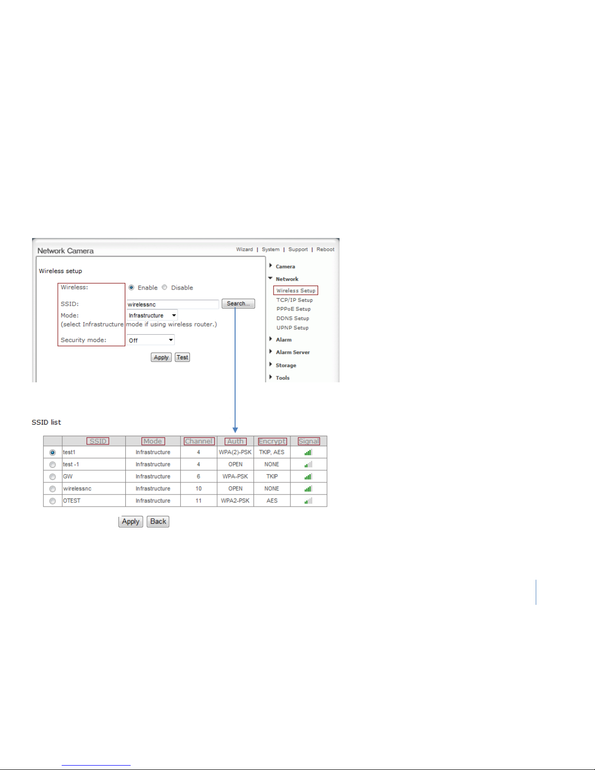
The camera corresponds to the wireless system based on
IEEE802.11b/g. Encryption establishes the security to
prevent unauthorized users to access the wireless data
communication.
Wireless Setup
Wireless- Enable or Disable the wireless function
SSID- Type the ID of the wireless network you want to
connect to using up to 32 ASCⅡ characters or click
Search to search for available networks.
Mode- Infrastructure mode and Adhoc mode
1) Adhoc Mode - Select Adhoc mode when the
camera is directly connected to your computer.
2) Infrastructure Mode - Select Infrastructure mode
when the camera is connected via an access point or
router.
When click Search (see figure left)
SSID- selects the network name you searched.
Mode- Infrastructure mode and Adhoc mode
Channel - Wifi channel
Auth – security mode
Encryption – None, TKIP, AES
Signal - It show out the strength of signal
Notes: These settings have to match those of your access
point or router. Please consult your access point or router
manual on how to verify or modify these settings.
Page 26
33
Network
Wireless Setup
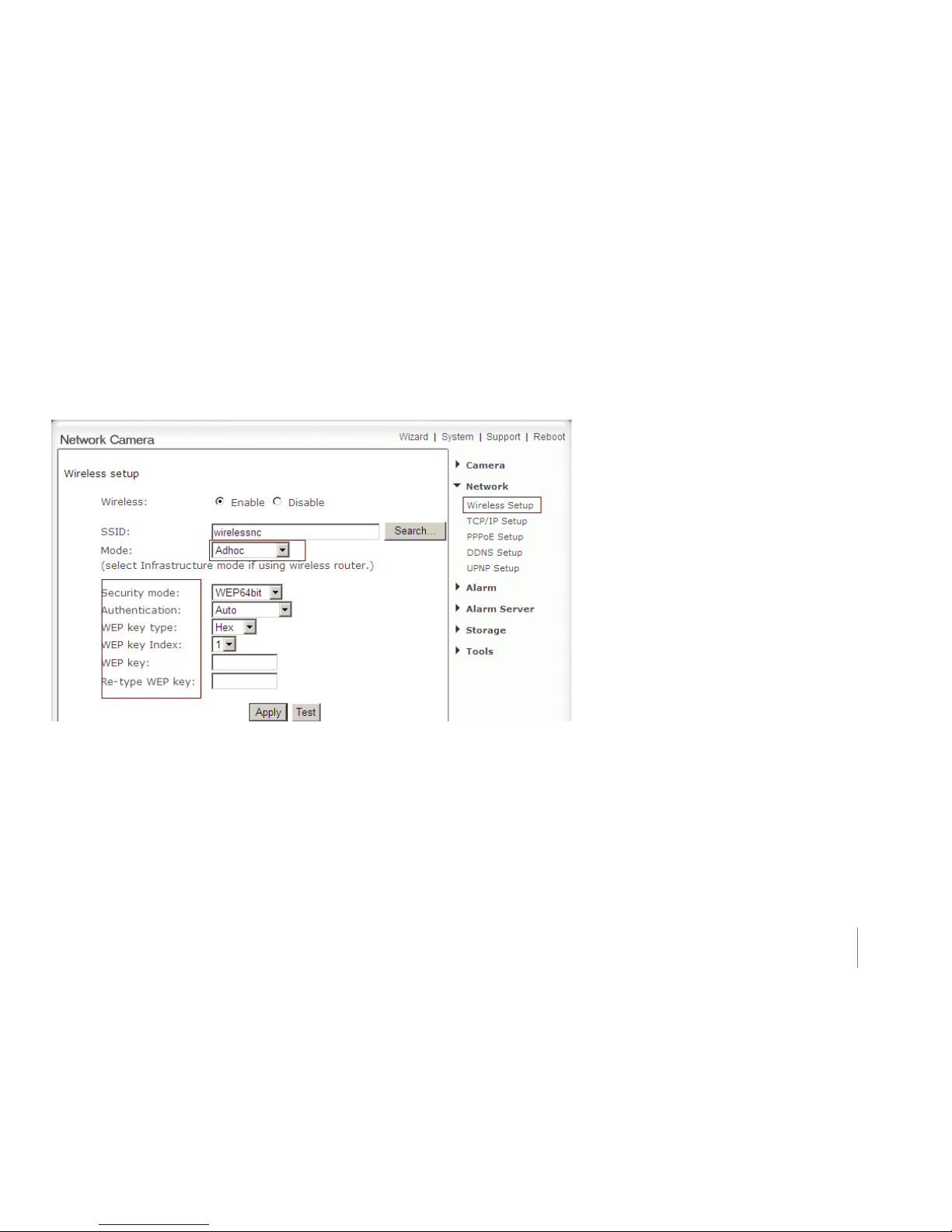
Adhoc Mode
When you select Adhoc mode. (See figure left)
Security mode - WEP64bit or WEP 128bit
Authentication - Select WEP authentication mode.
WEP Key type - Select the WEP key type. Either in
hexadecimal or ASCⅡ characters.
WEP key Index - Specify up to 4 WEP keys.
WEP Key - Type the password.
Re-type WEP Key - Re-confirm the password.
Click Apply to save changes.
Click Test to test whether connection is successful.
Page 27
34
Network
Wireless Setup
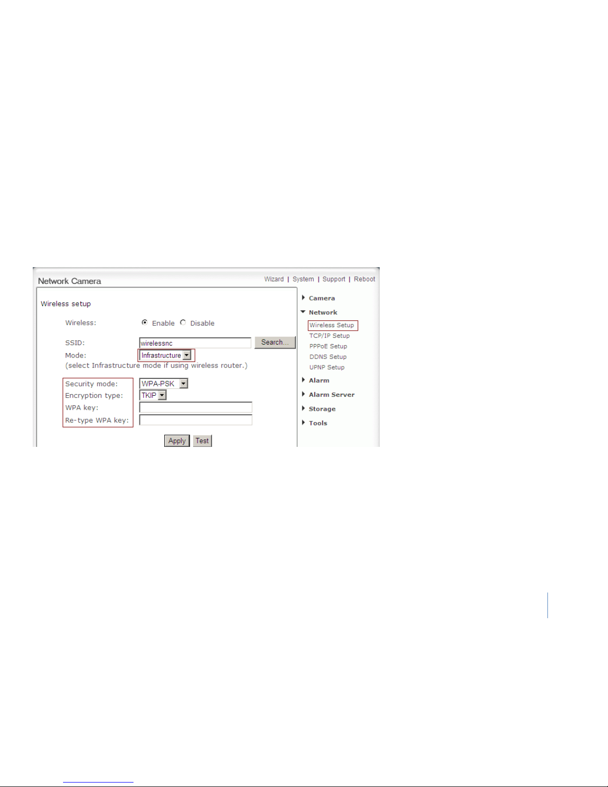
Infrastructure mode
When you select Infrastructure mode. (See figure
below)
Security mode- Security mode is not only
WEP64bit or WEP128bit but also WPA-PSK or
WPA2-PSK.
Encryption type- TKIP and AES.
WPA key-Type 8-63 characters as password.
Re-type WPA key- Re-confirm the password.
Click Apply to save changes.
Click Test to test whether connection is successful.
Page 28
35
Network
TCP/IP Setup
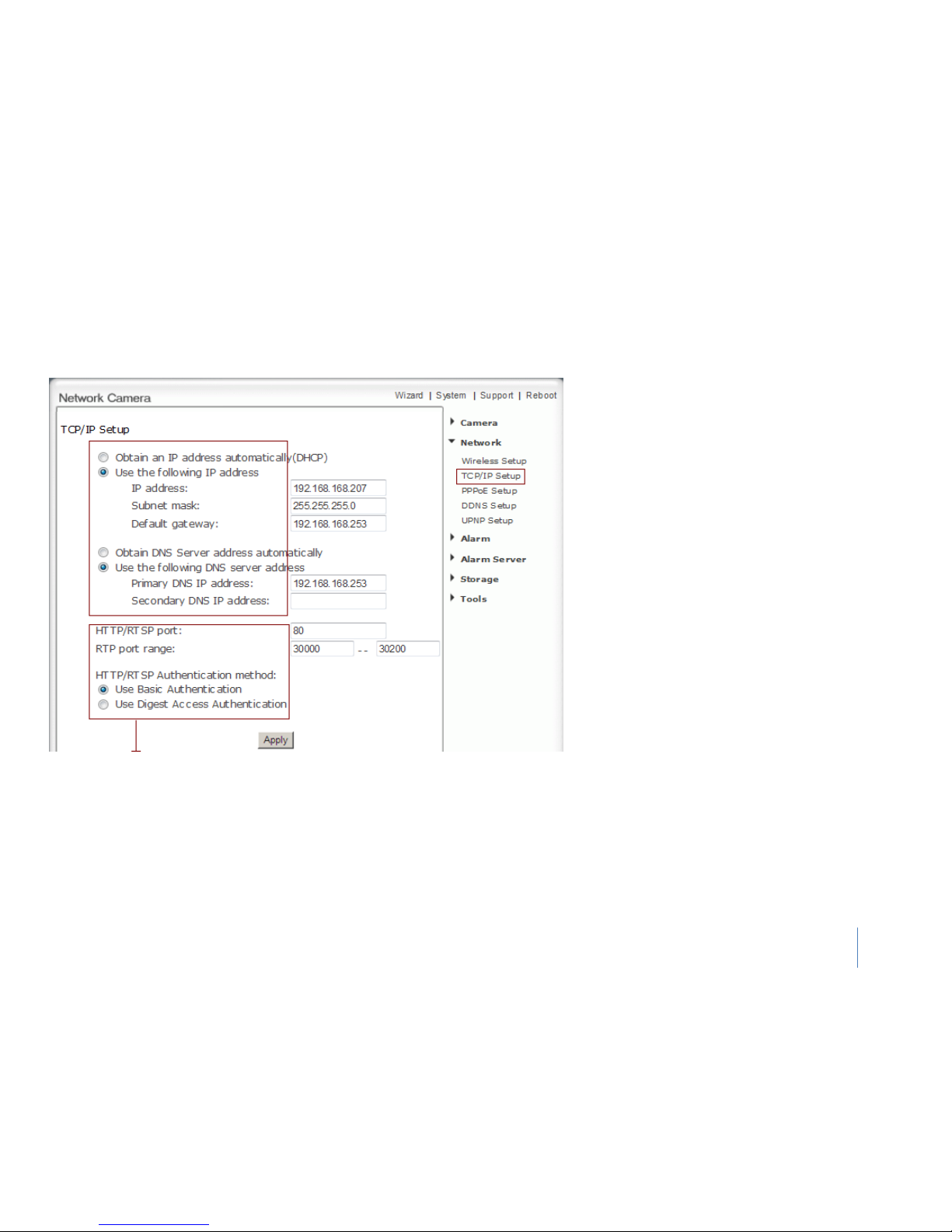
HTTP/RTSP port -The default HTTP port is 80, it is also be used as RTSP port.
RTP port range - It is for UPnP port forwarding, 1 camera actually use 2 RTP ports, one
for video, the other for audio. (See UPnP setup)
HTTP/RTSP Authentication method - Select Basic Authentication or Digest Access
Authentication.
The camera is set up to obtain the IP address
automatically (DHCP) by default. Should you may wish
to assign the IP address manually, use the TCP/IP Setup
page to enter the address details.
Obtain an IP address automatically (DHCP):
1) If your network supports a DHCP server (e.g.
router) select this option to have the IP address is
assigned automatically.
2) If you select Obtain an IP address automatically
and you should select Obtain a DNS Server address
automatically.
Use the following IP address: Select this option when a
fixed IP is required.
IP address - Type the IP address of your camera.
Subnet mask - Type the subnet mask.
Default gateway - Type the default gateway.
Obtain DNS Server address automatically:
If your network supports a DHCP server (e.g. router)
select this option to have the DNS Server address is
assigned automatically.
Use the following DNS server address:
Primary DNS IP address - Type the IP address of the
primary DNS server.
Secondary DNS IP address - Type the IP address of
the secondary DNS server, if necessary.
Page 29
36
Network
PPPoE Setup
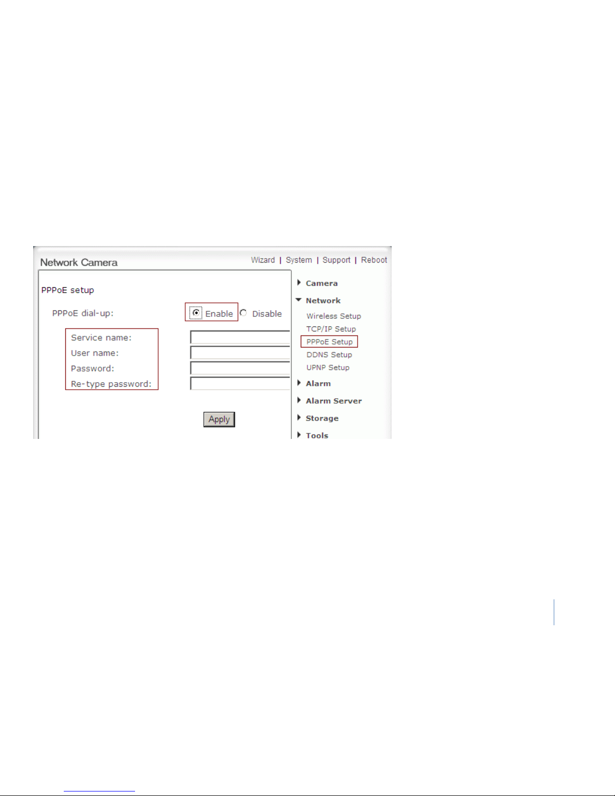
The camera can be installed without a PC on the
network. Some XDSL services use PPPoE
(Point-to-Point Protocol over Ethernet).
PPPoE dial-up - Enable or disable PPPoE
connection.
Service name - Either an ISP name or a class of
services that is configured on the PPPoE
server. This field may be left empty.
User name - Type the user name.
Password - Type the password.
Re-type password - Re-confirm the password.
Click Apply to confirm your settings.
Page 30
37
Network
DDNS Setup
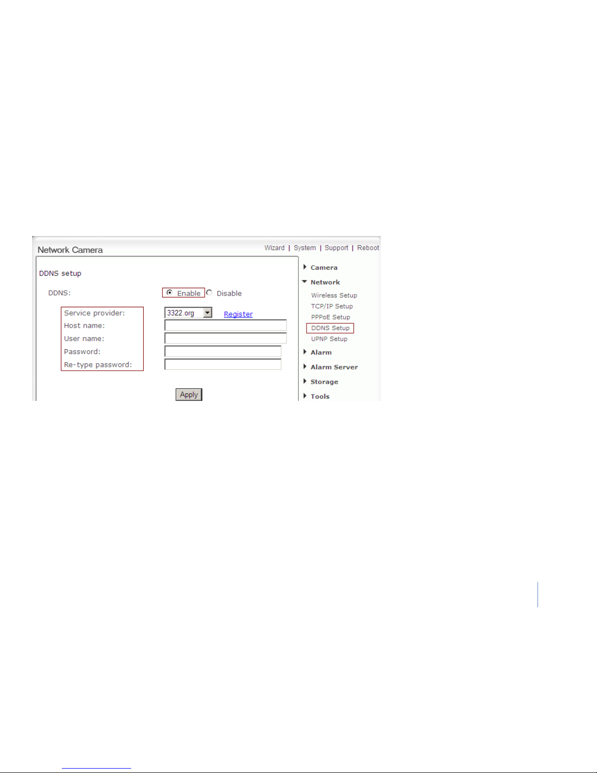
Dynamic DNS (DDNS) is simply a way of using a
static hostname to connect to a dynamic IP
address. When connected to your ISP, you are
assigned a temporary IP address. DDNS services
keep track of your IP address and route your
Domain name to that address when you wish to
connect to the camera from a remote location
DDNS - Enable or disable DDNS connection.
How to add DDNS
1. Enable the Dynamic DNS function.
2. Select your preferred DDNS service
provider from the list then click Register.
3. Enter the Host Name details and password
supplied by your DDNS service provider
when you registered.
Click Apply to confirm your settings
Page 31
38
Network
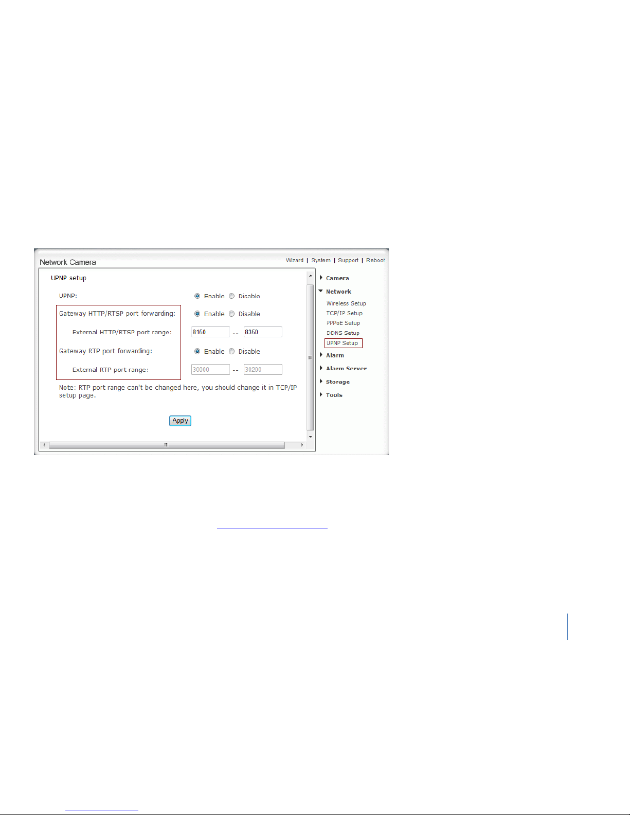
UPNP Setup
1. Tips: If set port range is 8150~8350, camera will ask router to add a port forwarding
rule automatically. In this rule, the internal port is camera default port 80, the external
port is 8150, and IP address is camera's IP. Use this setting, users can visit the camera
from Internet through the router with this URL
http://routeripaddress:8150.
2. Tips: If there are several cameras in Local Network, the first one which first be opened
will use 8150 as external port, and second one will use 8151, third one use 8152 etc.
Every camera will remember its port, it will preferentially use this port in next power on.
The camera supports UPnP which is enabled by
default. This function requires a Windows XP/Vista
operating system. It is a quick way to discover the
camera on your network. Please make sure that
the UPnP function is enabled on your PC.
UPnP - Enable or disable the UPnP function.
Gateway HTTP/RTSP port forwarding - Enable
or disable this function.
External HTTP/RTSP port range - Using this
port, automatically adds a port forwarding rule
to a router via UPnP protocol. Please Notes that
not all routers support this function. Refer to
your router manual for further details.
Gateway RTP port forwarding - Enable this
function, users can use mobile phone,
RealPlayer or QuickTime Player to visit the
camera from Internet through the router.
External RTP port range - 30000—30200
default. (See TCP/IP setup)
Click Apply to confirm your setting.
Page 32
39
System
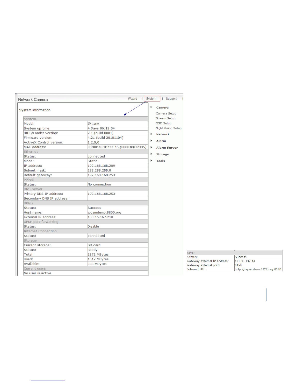
System information
Click System at the top right of Settings page to
show the System information. See figure
This is a very useful screen as it shows you what
parts of your Camera are properly or incorrectly
setup.
Use it to find your DDNS address, static IP,
internal IP, gateway and much more.
It also shows you which Users are currently
viewing the camera, and from what IP address
they come from.
If DDNS setup successfully and go into effect,
Internet URL will show DDNS host name instead.
(See figure below for example)
Page 33
40
Alarm
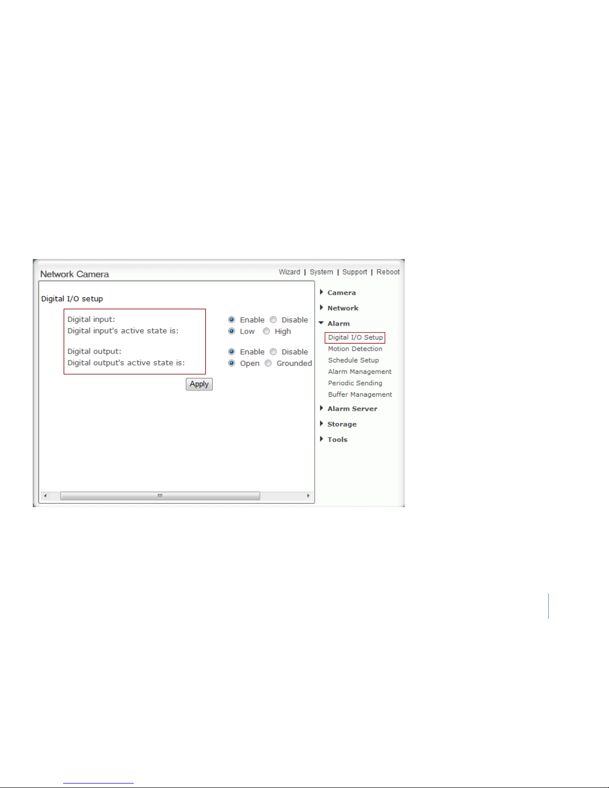
Digital I/O Setup
Digital I/O Setup:
Digital input –Enable or Disable the
function
Digital input’s active state is:
Low – with low active method
High – with High active method
Digital output – Enable or Disable the
function
Digital output’s active state is:
Open – open the circuit
Grounded – with grounded situation
Page 34
41
Alarm
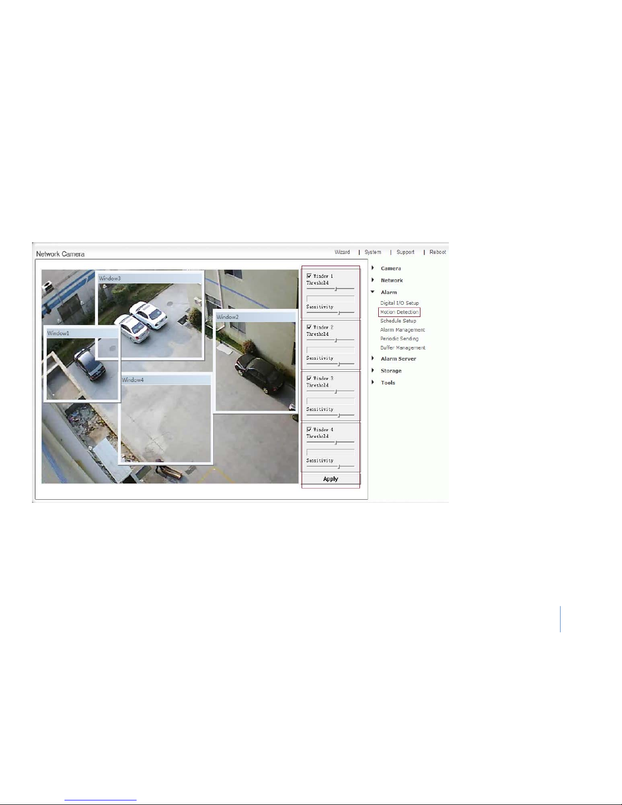
Motion Detection
Motion Detection can trigger an alarm that sends images or video feed via e-mail or FTP (File Transfer Protocol). You can set up to four different
Motion Detection windows.
Window - Check this box to enable the window.
Threshold - Set the threshold bar to the amount of motion required to trigger the alarm.
Sensitivity- Set the measurable difference between two sequential images that would indicate motion.
Click Apply to confirm your setting.
Page 35
42
Alarm
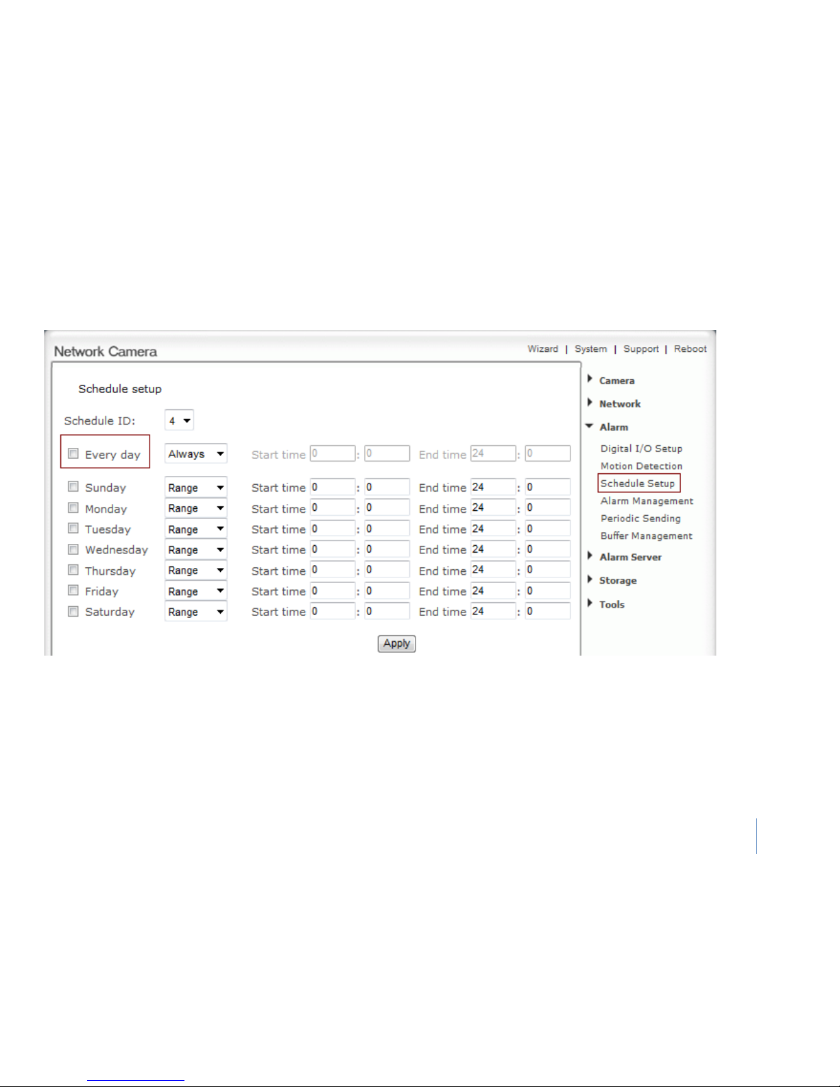
Schedule Setup
Alarm Sending, Periodical Sending and Buffer Sending sends images via e-mail or FTP according to schedule setup
Schedule ID – you could setup with 4 period of time
Every day- Select every day or not. Sunday ~ Saturday- Select Sunday ~ Saturday or not.
Always- Enable in any time.
Range- Enable between start time and end time.
Except- Enable except start time to end time.
Click Apply to confirm your setting.
Page 36
43
Alarm
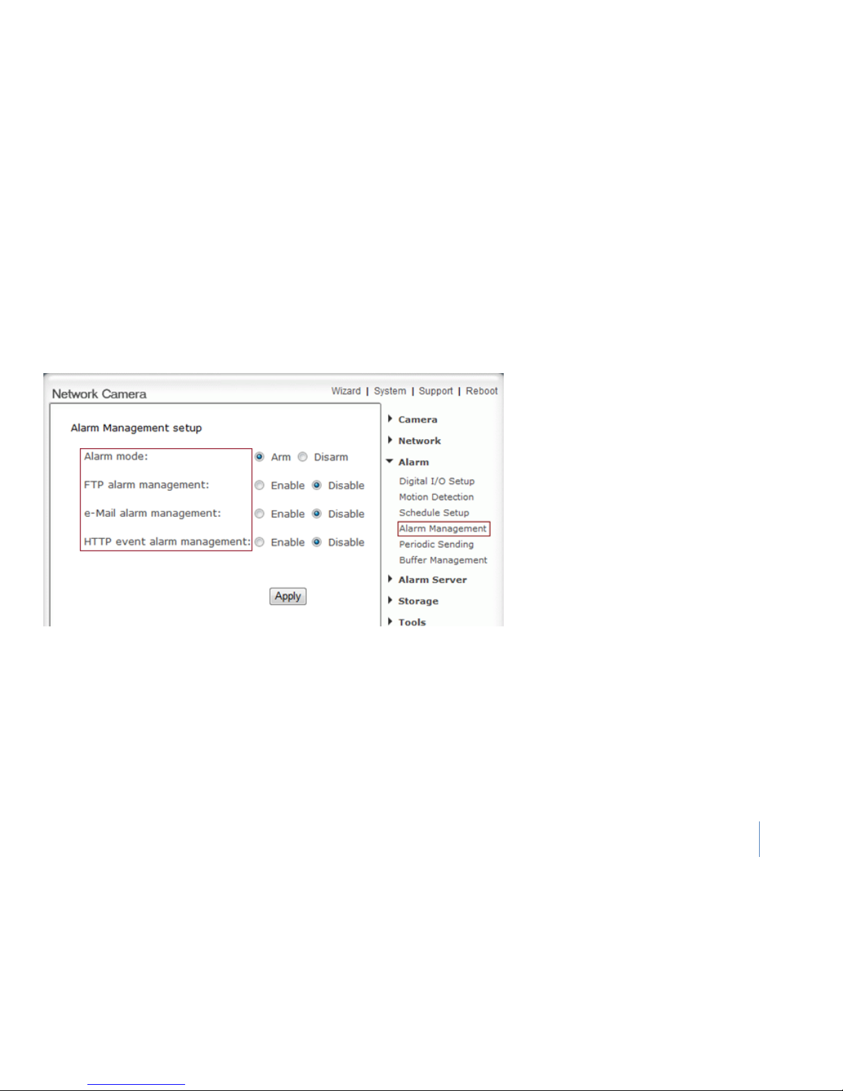
Alarm Management
FTP alarm management
Motion Detection can trigger an alarm that sends
images via FTP or e-mail and send URL via HTTP.
Alarm management setup:
Alarm mode - Enable or disable all alarm.
FTP alarm sending - Enable or disable FTP alarm
sending function.
e-Mail alarm sending - Enable or disable e-Mail
alarm sending function.
HTTP event alarm sending -
Enable or disable
HTTP event alarm function.
Page 37
44
Alarm
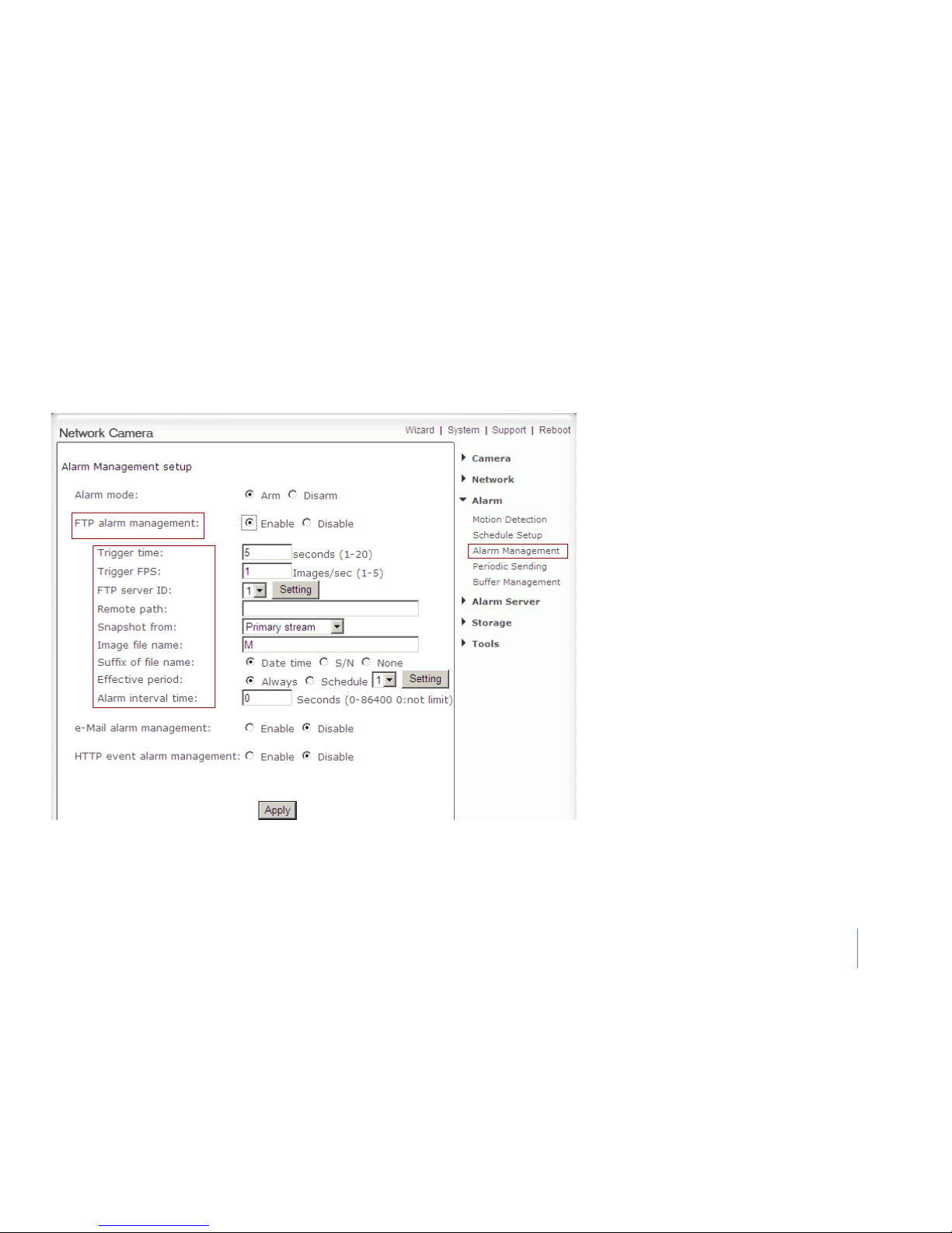
Alarm Management
FTP alarm management
FTP alarm management:
Trigger time - How many seconds does camera
keep snapshot the images after get a motion
alarm.
Trigger FPS - How many images does camera
snapshot every second after get a motion alarm.
FTP server ID - Select one FTP server, click Setting
to set FTP server.
Remote path - Path where to save the image file
on the FTP server.
Snapshot from -
Select source stream that
snapshot from.
Image file name - Type image file name.
Suffix of file name - Select suffix of file name.
Effective period - Select Effective period. If select
schedule, click Setting to set schedule.
Alarm interval time - Scope: 0-86400 sec, when
the alarm time remains at 0 second, no alarm
trigger restricted. Otherwise, the triggering
interval will just be the setting alarm time. Alarm
within the time will not be triggered.
Page 38
45
Alarm
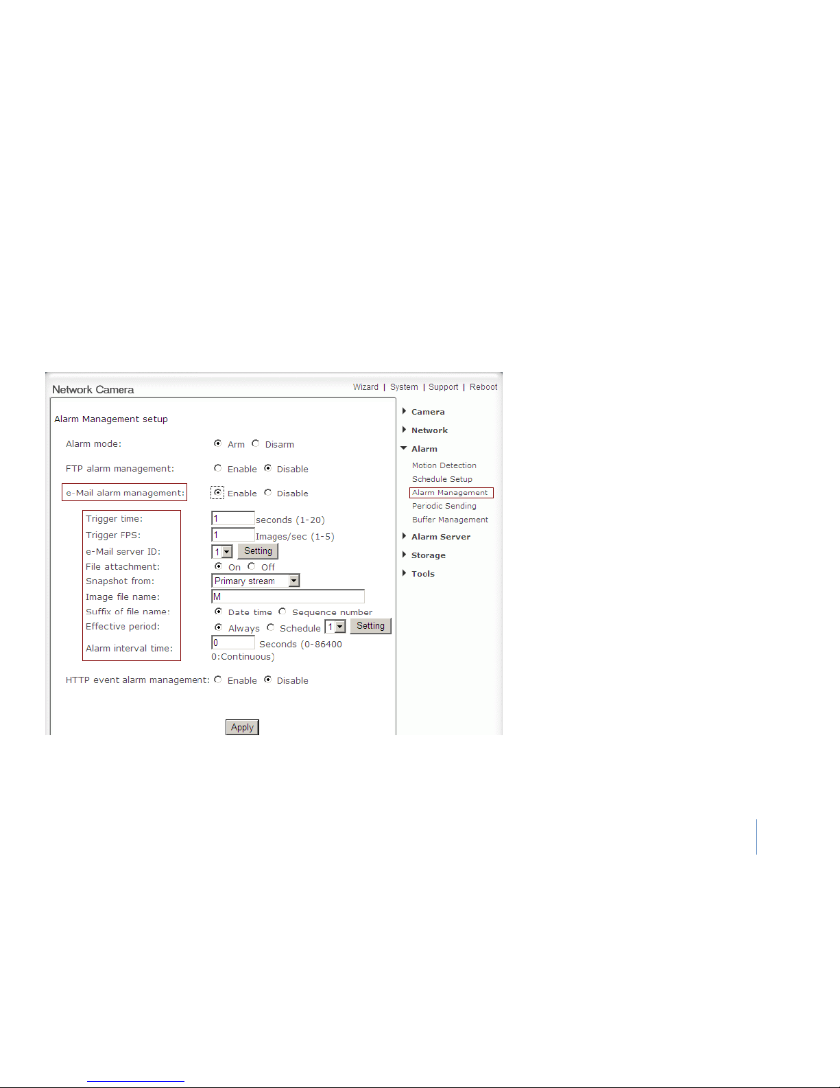
Alarm Management
e-Mail alarm management
e-Mail alarm management:
Trigger time - How many seconds does camera
keep snapshot the images after get a motion
alarm.
Trigger FPS - How many images does camera
snapshot every second after get a motion alarm.
e-Mail server ID - Select one e-Mail server, click
Setting to set e-Mail server.
File attachment - Switch file attachment on or off.
Snapshot from -
Select source stream that
snapshot from.
Image file name - Type image file name.
Suffix of file name - Select suffix of file name.
Effective period - Select Effective period. If select
schedule, click Setting to set schedule.
Alarm interval time - Scope: 0-86400 secs, when
the alarm time remains at 0 second, no alarm
trigger restricted. Otherwise, the triggering
interval will just be the setting alarm time. Alarm
within the time will not be triggered.
Click Apply to confirm your setting.
Page 39
46
Alarm
Alarm Management
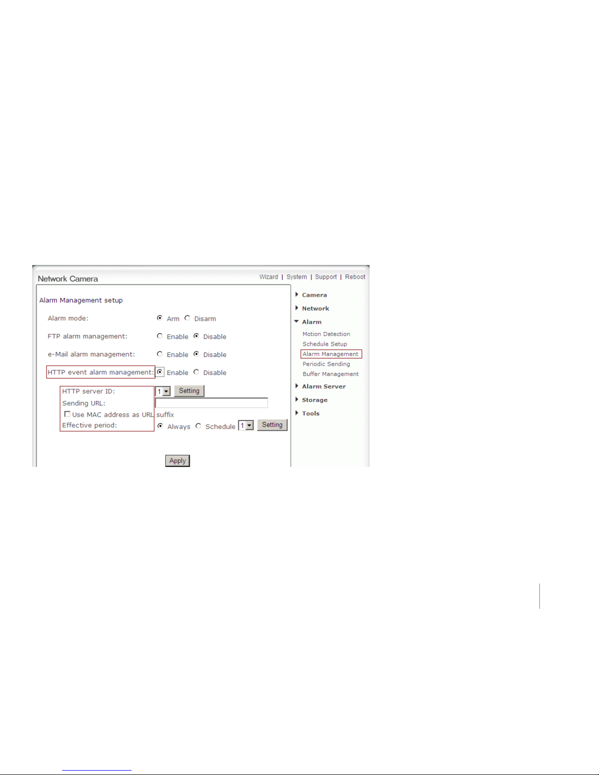
HTTP event alarm management
HTTP event alarm management
HTTP server ID - Select HTTP server ID, click
Setting to set HTTP server.
Sending URL - Type URL which will be sent to
HTTP server.
Use MAC address as URL suffix - Enable or
disable this function.
Effective period - Select effective period. If
select schedule, click Setting to set schedule.
Click Apply to confirm your setting.
Page 40
47
Alarm
Periodic Sending
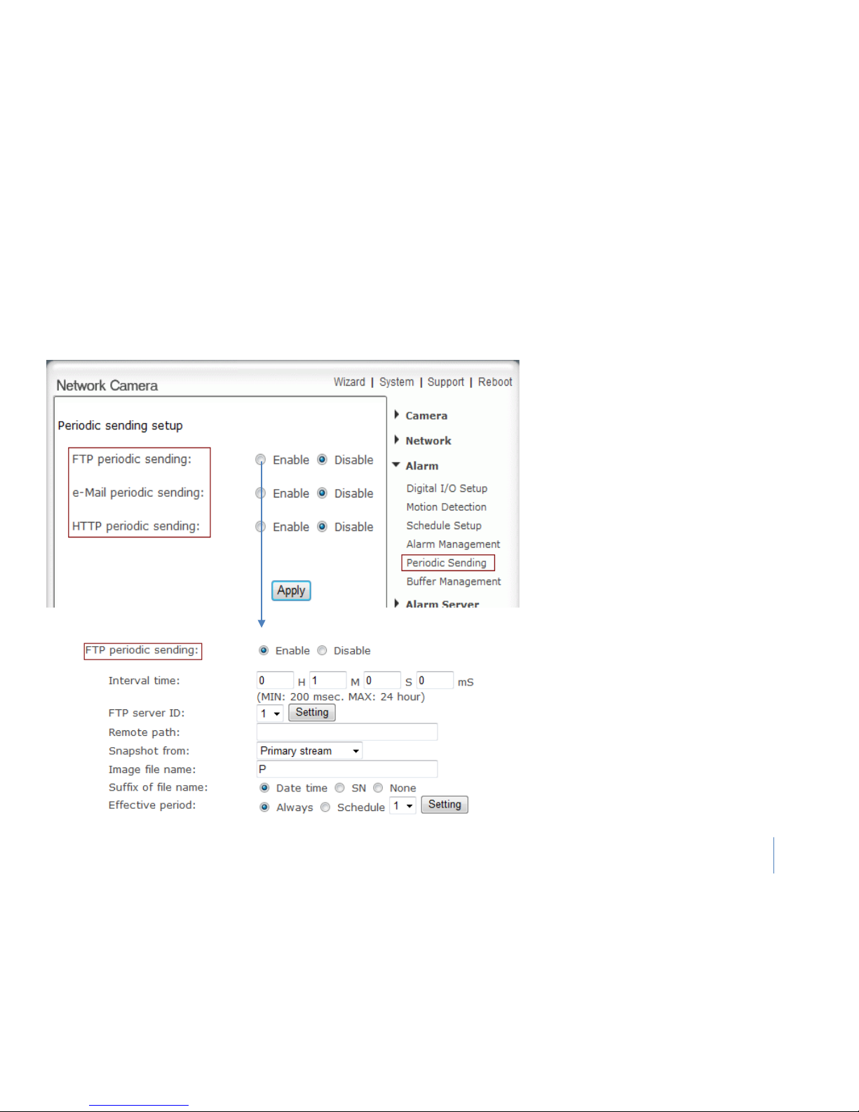
FTP periodic sending
The camera can send images via FTP or e-mail and
send URL via HTTP periodically.
Periodic sending setup:
FTP periodic sending - Enable or disable FTP
upload periodically.
e-Mail periodic sending - Enable or disable e-Mail
upload periodically.
HTTP periodic sending - Enable or disable HTTP
upload periodically.
FTP periodic sending
Interval time -
Type the interval at which you
want to send the images periodically.
FTP server ID - Select one FTP server, click Setting
to set FTP server.
Remote path - Path where to save the image file
on the FTP server.
Snapshot from -
Select stream that snapshot
from.
Image file name - Type image file name.
Suffix of file name - Select suffix of file name.
Effective period - Select Effective period. If select
schedule, click Setting to set schedule.
Notes: The notifications use the camera’s internal
clock. Please make sure the camera’s Date and Time
are correct.
Page 41
48
Alarm
Periodic Sending
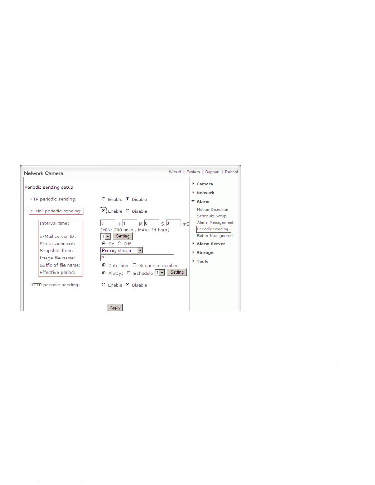
e-Mail periodic sending
e-Mail periodic sending
Interval time - Type the interval at which
you want to send the images periodically.
e-Mail server ID - Select one e-Mail server,
click Setting to set e-Mail server.
File attachment - switch file attachment on
or off.
Snapshot from -
Select stream that
snapshot from.
Image file name - Type image file name.
Suffix of file name - Select suffix of file
name.
Effective period - Select Effective period. If
select schedule, click Setting to set schedule.
Click Apply to confirm your setting
Page 42
49
Alarm
Periodic Sending
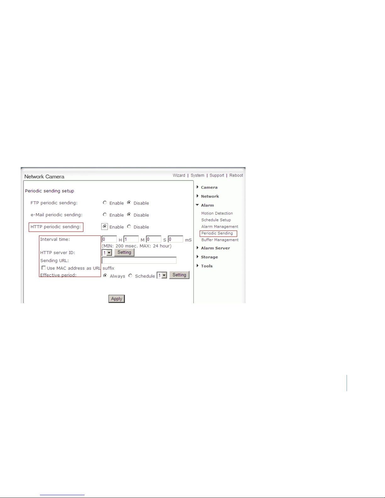
HTTP Periodic sending
HTTP Periodic sending
Interval time - Type the interval at which you
want to send the URL periodically.
HTTP server ID - Select HTTP server ID, click
Setting to set HTTP server.
Sending URL - Type URL which can be sent to
HTTP server..
Use MAC address as URL suffix - Enable or
disable this function.
Effective period - Set Effective period. If
select schedule, click Setting to set schedule.
Click Apply to confirm your setting
Page 43
50
Alarm
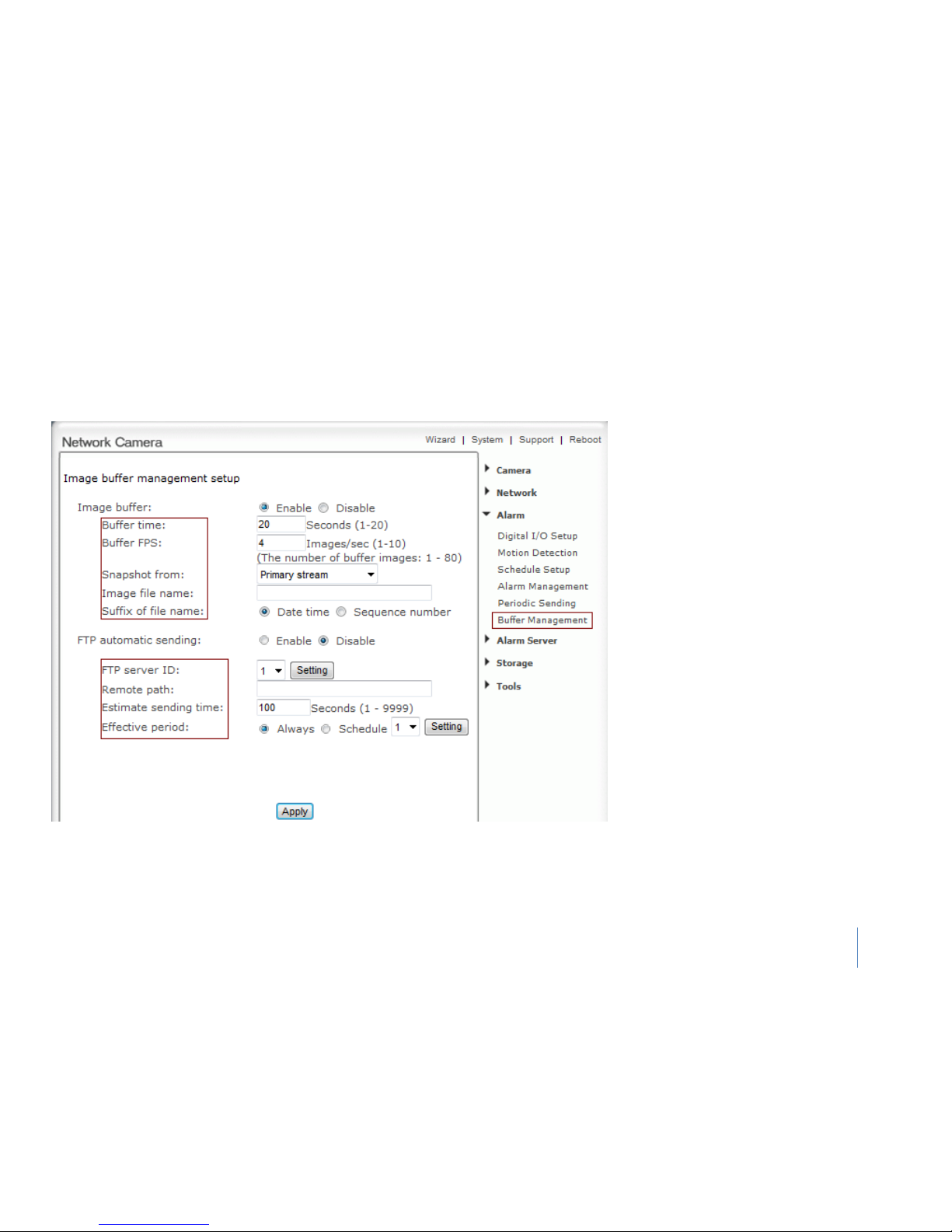
Buffer Management
.
Notes: This function just can be used when SD card does not plug in the SD slot of cameras.
The camera can be configured to send images
via FTP when the Motion Detection alarm is
triggered
Image buffer - Enable or disable this function.
Click Browse to preview images.
Buffer time - Type buffer time.
Buffer FPS - Type buffer FPS.
Snapshot from - Select stream that snapshot
from.
Image file name - Type image file name.
Suffix of file name - Select suffix of file
name.
FTP automatic sending - Enable or disable this
function.
FTP server ID - Select one FTP server, click
Setting to set FTP server.
Remote path - Path where to save the image
file on the FTP server.
Estimate sending time - Type estimate time
that all buffer images send completed.
Effective period - Select Effective period. If
select schedule, click Setting to set schedule.
Click Apply to confirm your setting.
Page 44
51
Alarm Server
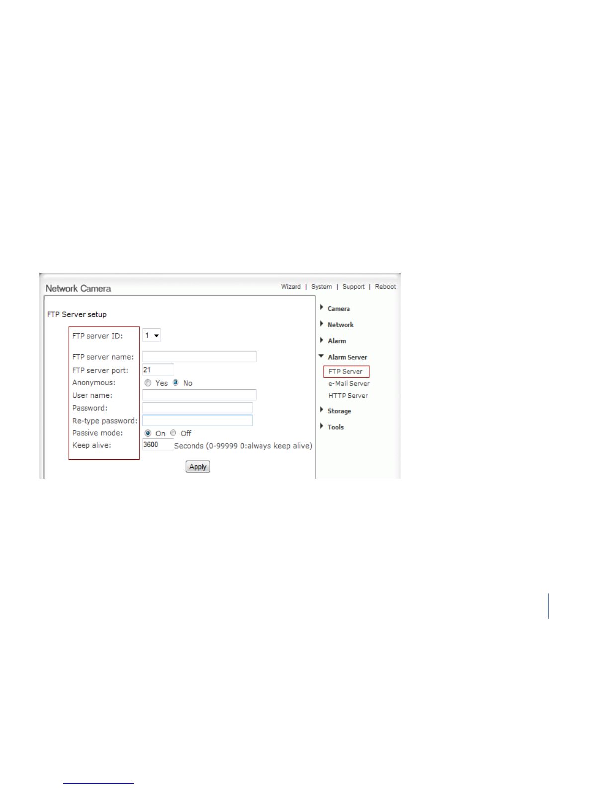
FTP Server
FTP server setup
FTP server ID - Select FTP server ID.
FTP server name - Type the name or IP
address of the FTP server.
FTP server port - The default port
number is 21.
Anonymous - Enable or disable
anonymous login.
User name - Type your user name.
Password - Type your password.
Re-type password - Re-type your
password.
Passive mode - Switch passive mode on
or off.
Keep alive - Type the time which keep
alive with FTP server.
Click Apply to confirm your settings.
Page 45
52
Alarm Server
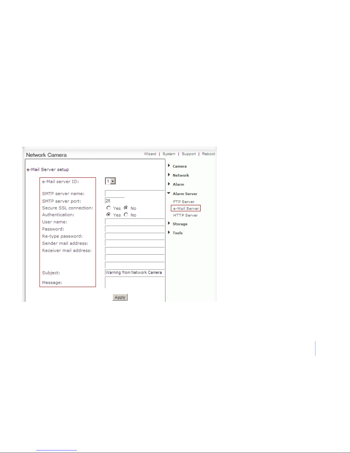
e-Mail Server
Subject - Subject of the e-mail, entering a relevant subject will help identify the alarm
better.
Message - Type the text you wish to appear in the e-mail.
e-Mail Server setup:
e-Mail server ID - Select e-Mail server ID.
SMTP server name - Type the name or IP
address of the SMTP server you want to use
for sending the e-Mails. Please Notes that
networks do not allow e-mail relaying. Check
with your system administrator for more
details.
SMTP server port - The default value is 25.
Secure SSL connection - Select whether use
SSL connection.
Authentication - Select the authentication
required by the SMTP server.
User name- & Password - Type the user name
and password of the e-Mail account you wish
to use.
This field is required if your SMTP server
requires authentication.
Re-type password - Re-type the password.
Sender e-mail address - Type the e-mail
address of the account you are using to send
the e-Mail.
Receiver e-mail address - Type the recipients’
e-mail addresses (Up to 3 addresses can be
entered).
Click Apply to confirm your settings.
Page 46
53
Alarm Server
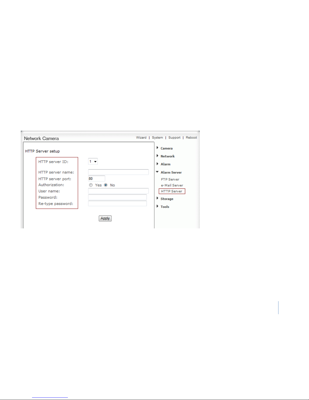
HTTP Server
HTTP Server setup:
HTTP server ID - Select HTTP server ID.
HTTP server name - Type the HTTP server
name.
HTTP server port - Type the HTTP server
port.
Authentication - Select the authentication
required by the HTTP server.
User name - Type the user name.
Password - Type the password.
Re-type password - Re-confirm the
password.
Click Apply to confirm your settings.
Page 47
54
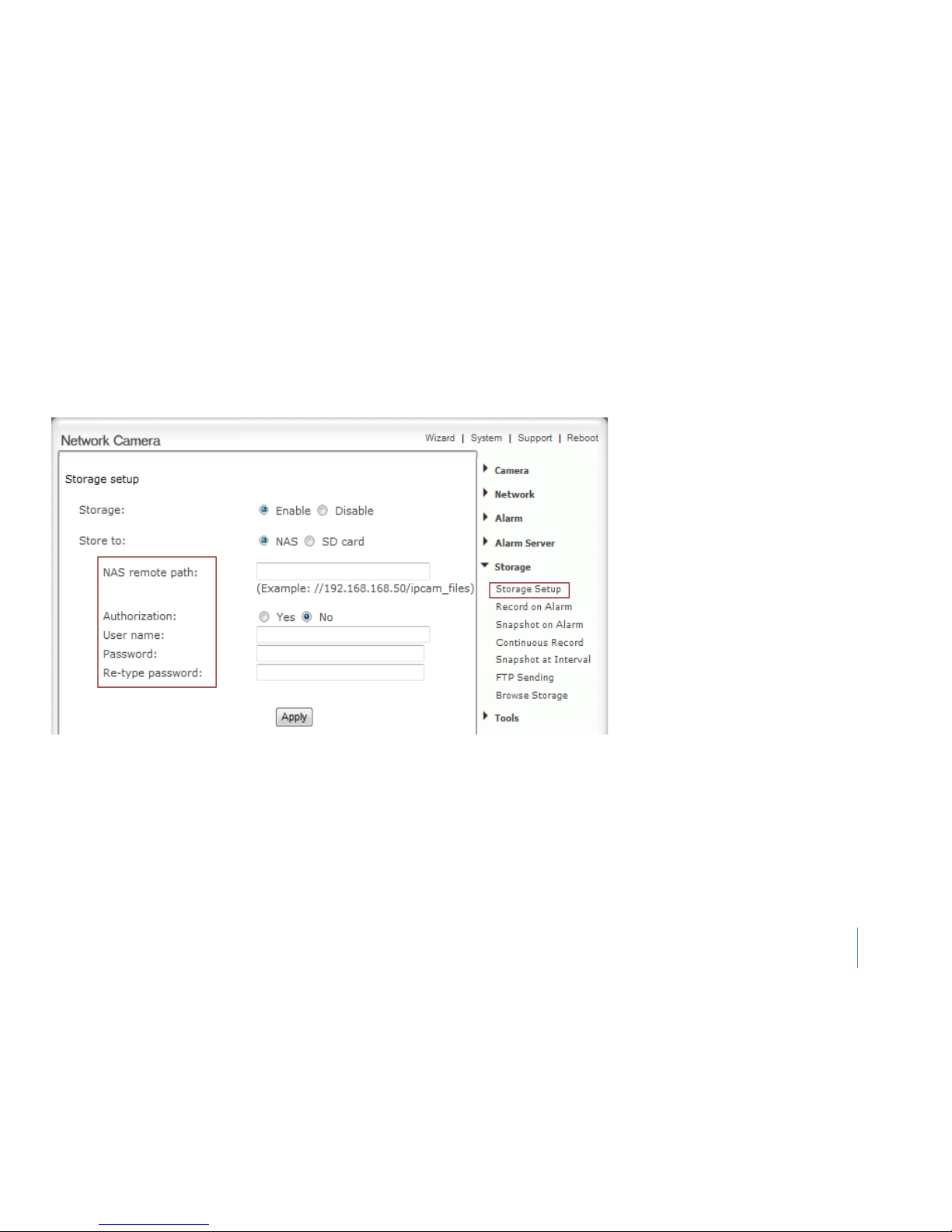
Storage
Storage setup
Notes:
PC could serve as NAS as long as the PC support SMB/CIFS protocol and set shared
folders.
Select storage destination to NAS or SD card.
Storage setup:
Storage - Enable or Disable the storage
function.
Store to - When select storage destination
for videotape and photograph, NAS (network
attached storage) or SD card can be used.
While choosing NAS, SMB/CIFS should be
used as File transmission protocol.
NAS remote path - Appoint NAS remote link
address and shared folders.
Authorization - Identity authentication of
accessing shared folders in NAS.
User name - Type the user name.
Password - Type the password.
Re-type password - Re-confirm the
password.
Click Apply to confirm your settings.
Page 48
55
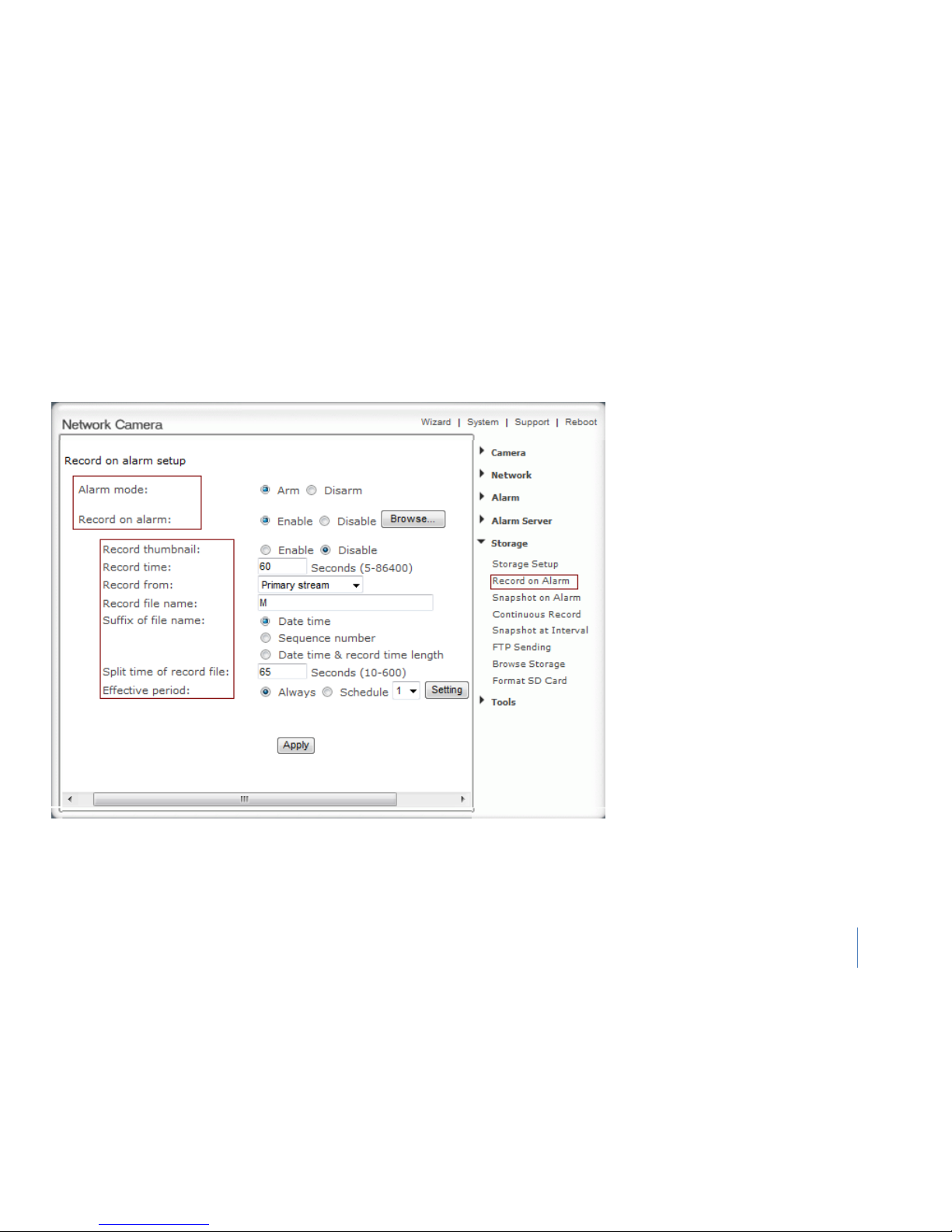
Storage
Record on Alarm
Record on alarm setup:
Alarm mode - Enable or disable all alarm.
Record on alarm - Enable or disable alarm
recording function.
Record thumbnail –this function will be able
to view the thumbnail image of the .MOV
files by .THM files created in the browse
storage
Record time - how
many seconds does
camera keep recording after a motion alarm.
Record from - Select source stream that
record from.
Record file name - Type record file name.
Suffix of file name - Select suffix of file
name.
Split time of record file - How many seconds
does every recording file save video and
audio.
Effective period - Select Effective period. If
select schedule, click “Setting” to set
schedule
Click Apply to confirm your settings.
Page 49
56
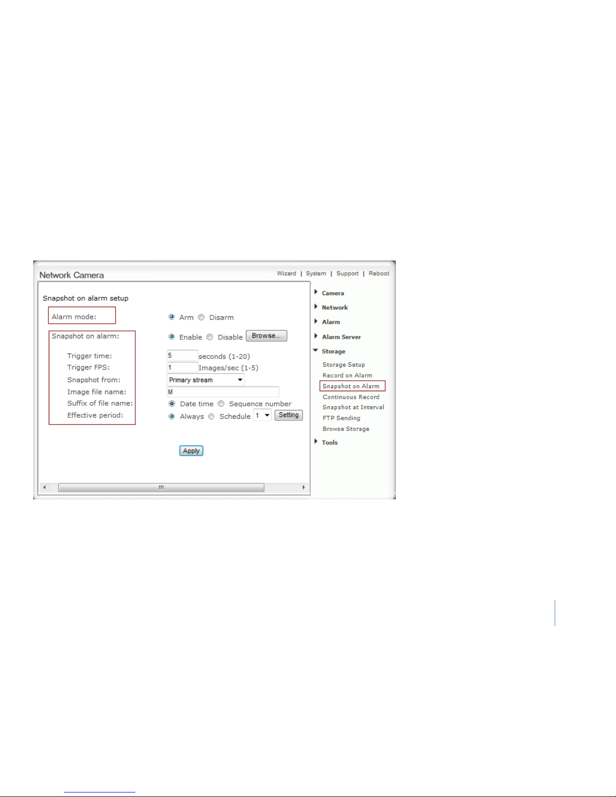
Storage
Snapshot on Alarm
Snapshot on alarm setup:
Alarm mode - Enable or disable all alarm.
Snapshot on alarm -
Enable or disable
alarm snapshot function.
Trigger time - How many seconds does
camera keep snapshot the images after
get a motion alarm.
Trigger FPS - How many images does
camera snapshot every second after get
a motion alarm.
Snapshot from - Select source stream
that snapshot from.
Image file name - Type image file name.
Suffix of file name- Select suffix of file
name.
Effective period -
Select Effective
period. If select schedule, click “Setting”
to set schedule.
Click Apply to confirm your settings.
Page 50
57
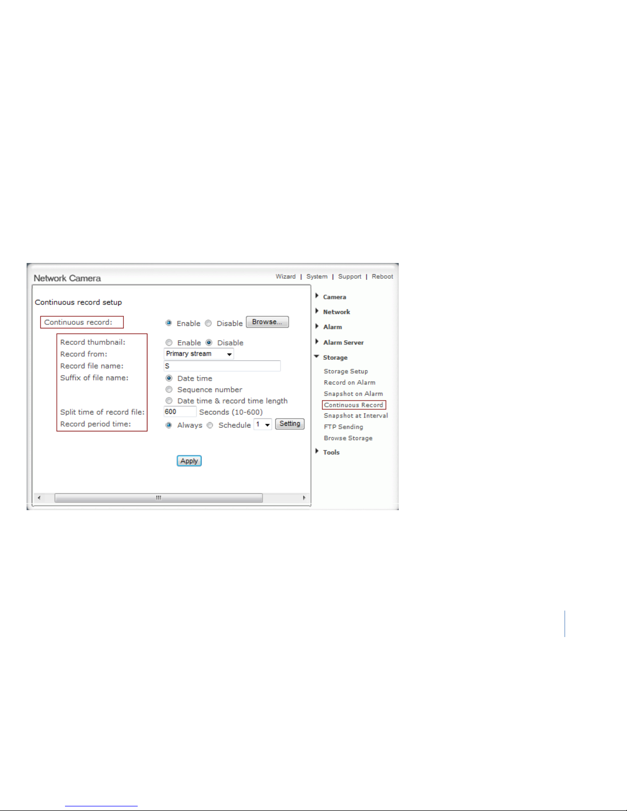
Storage
Continuous Record
Continuous record setup
Continuous record -
Enable or disable
continuous recording function.
Record thumbnail – this function will be able
to view the thumbnail image of the .MOV files
by .THM files created in the browse storage
Record from - Select source stream that record
from.
Record file name - Type record file name.
Suffix of file name - Select suffix of file name.
Split time of record file - How many seconds
does every recording file save video and audio.
Record period time - Select record period
time. If select schedule, click “Setting” to set
schedule.
Click Apply to confirm your settings.
Page 51
58
Storage
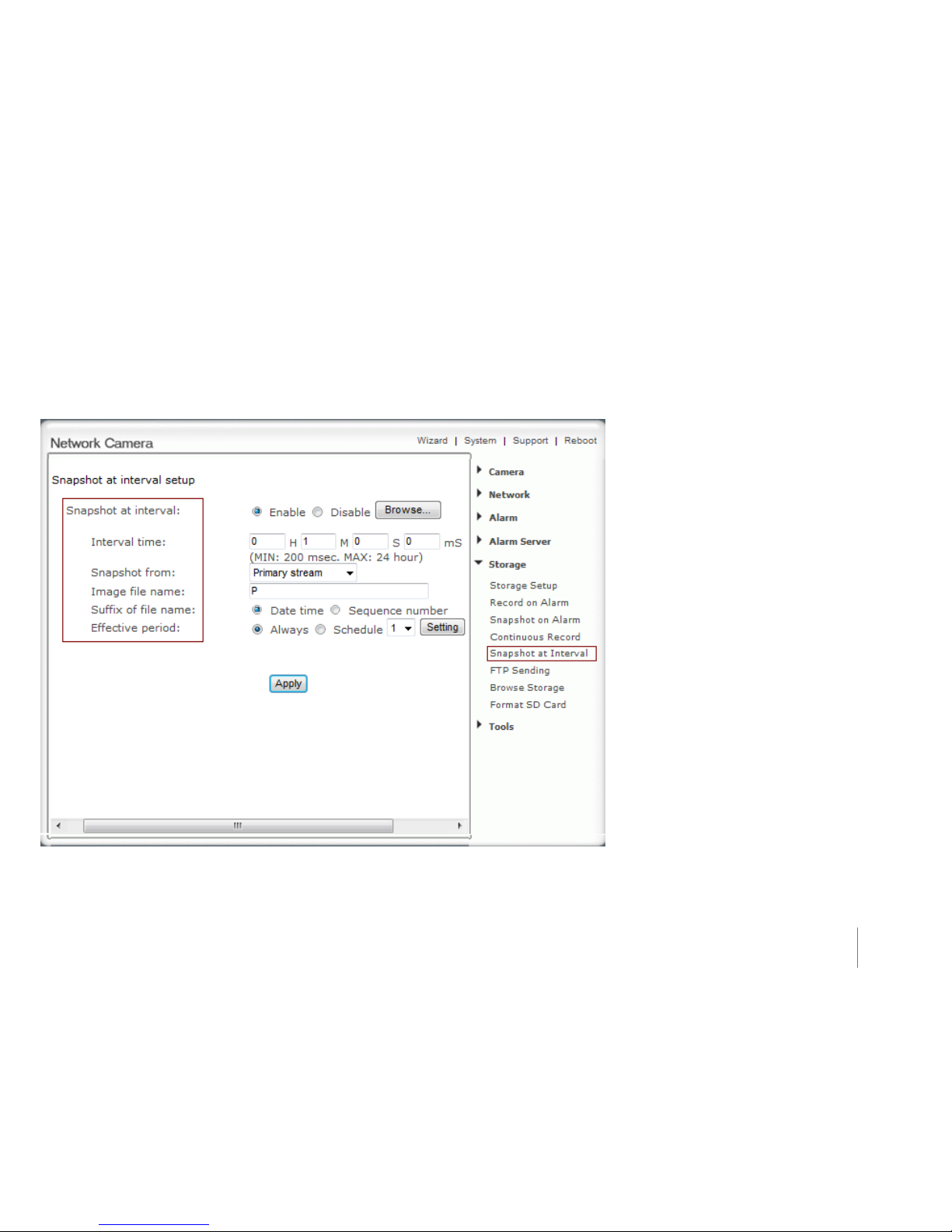
Snapshot at Interval
Snapshot at interval setup:
Snapshot at interval - enable or disable interval
snapshot function
Interval time - Type the interval at which you
want to save snapshot to SD card periodically.
Snapshot from - Select stream that snapshot
from.
Image file name - Type image file name.
Suffix of file name - Select suffix of file name.
Effective period - Select Effective period. If
select schedule, click “Setting” to set schedule.
Click Apply to confirm your settings.
Page 52
59
Storage
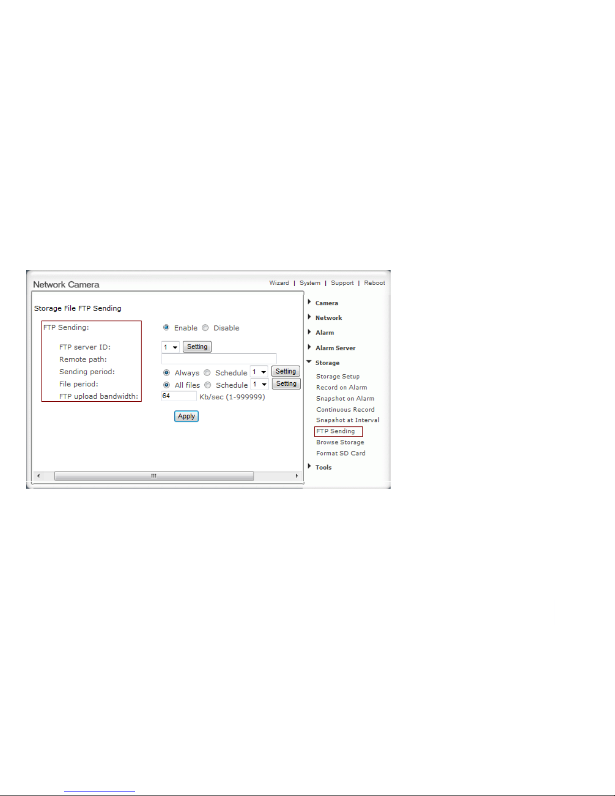
FTP Sending
.
Notes:
when users visit the video, uploading will automatically interrupt, and will restart when
users stop visit the video
This function is used for sending the files to
FTP server.
Storage File FTP Sending:
FTP Sending – Enable or Disable the FTP sending
function
FTP server ID - Select one FTP server, click
“Setting” to set FTP server.
Remote path - Path where to save the file on
the FTP server.
Sending period -
Select sending period. If
select schedule, click “Setting” to set schedule.
File period - Select the files which creation
time is in period to sending. If select schedule,
click “Setting” to set schedule.
FTP upload bandwidth - Evaluate the
uploading speed of FTP sending files.
Click Apply to confirm your settings.
Page 53
60
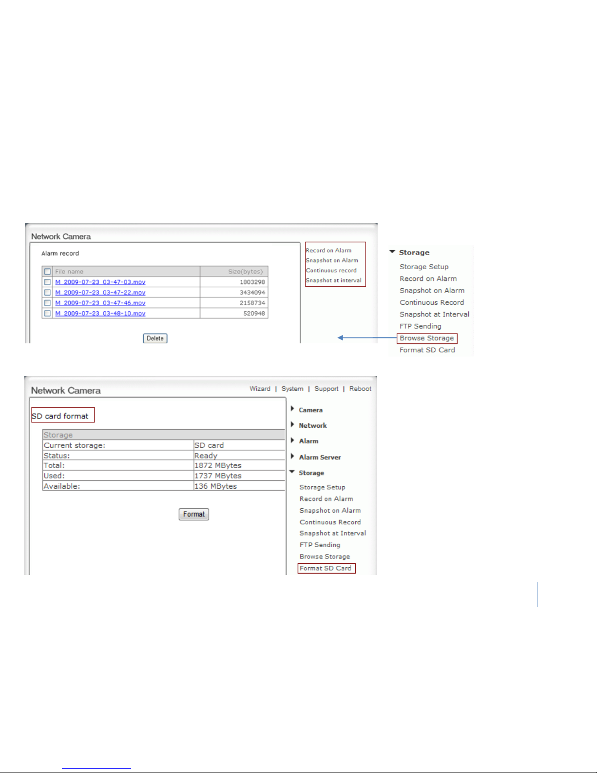
Browse Storage
Format SD Card
When click Browse Storage and see figure left,
you can browse, download, and delete the
snapshot and recording files in it.
To format SD card, all files will be lost after
format
Page 54
61
Tools
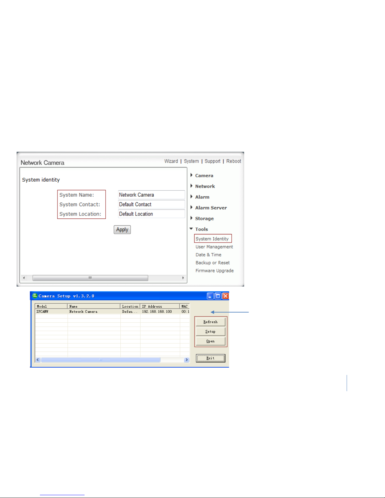
System Identity
System identity:
System Name - Type a name to easily identify
the camera.
System Contact - Type the contact name of
the administrator of the camera.
System Location - Type the location of the
camera.
Tips: The information you fill in can be displayed
on the camera. It can help to distinguish different
Network Cameras in the network. (See figure left)
Page 55
62
Tools
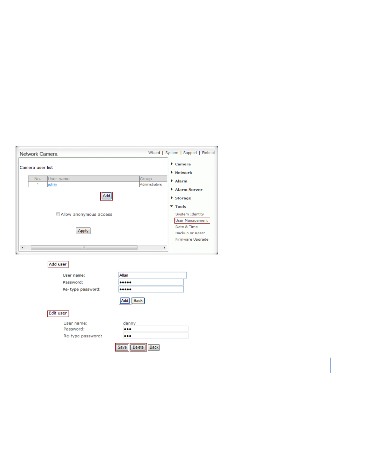
User Management
Notes:
1) A maximum of 16 users are allowed to access the
camera simultaneously.
2) As the number of simultaneously users increase, the
overall performance will decrease. This is dependent
on the Network bandwidth.
Adding users
1. Click “Add” on the “Camera User List” page.
2. Enter the User name, Password and re-confirm
the password then click “Add”.
Edit user
To edit a user’s password, click on the user name then
enter the new password for that user twice and click
“Save”. To delete a user, click on the user name then
click “Delete”.
Page 56
63
Tools
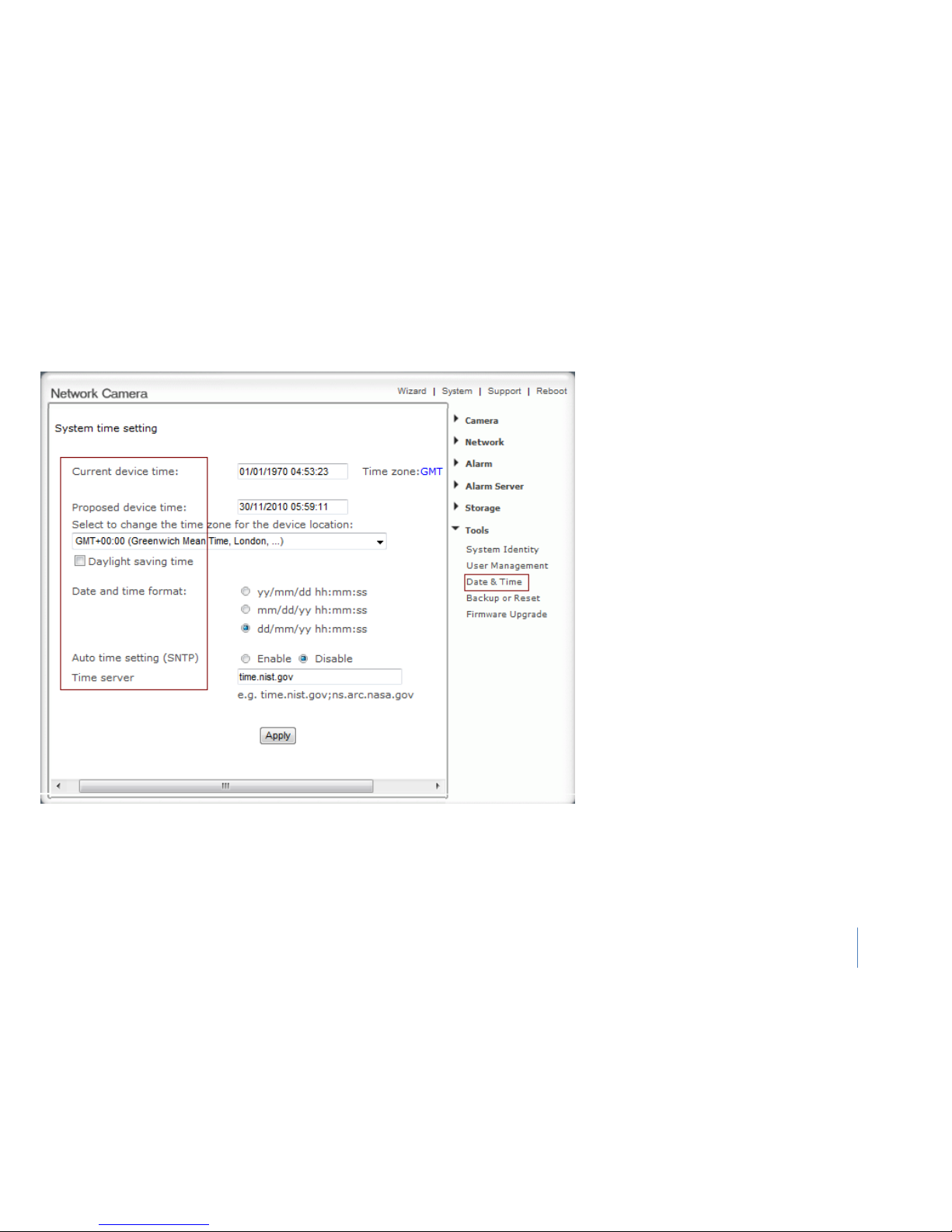
Date & Time
Notes:
1) If the SNTP server is not found the camera’s time will be synchronized with the PC time.
2) The camera has a built-in RTC (Real-time Clock) that keeps track of the time even when
power is disconnected.
System time setting:
Current device time – camera’s Internal time.
Proposed device time -
PC system time. On
clicking Apply the camera’s Internal time will be
changed to this time.
Select to change the time zone for the device
location - choose proper time zone.
Daylight saving time - Daylight Saving Time (or
summertime as it is called in many countries) is a
way of getting more light out of the day by
advancing clocks by one hour during the summer.
Date and time format - Select date and time
format.
Auto time setting (SNTP) - Enable or disable this
function.
Time server - Type one SNTP server name in the
box.
Click Apply to confirm your settings.
Page 57
64
Tools
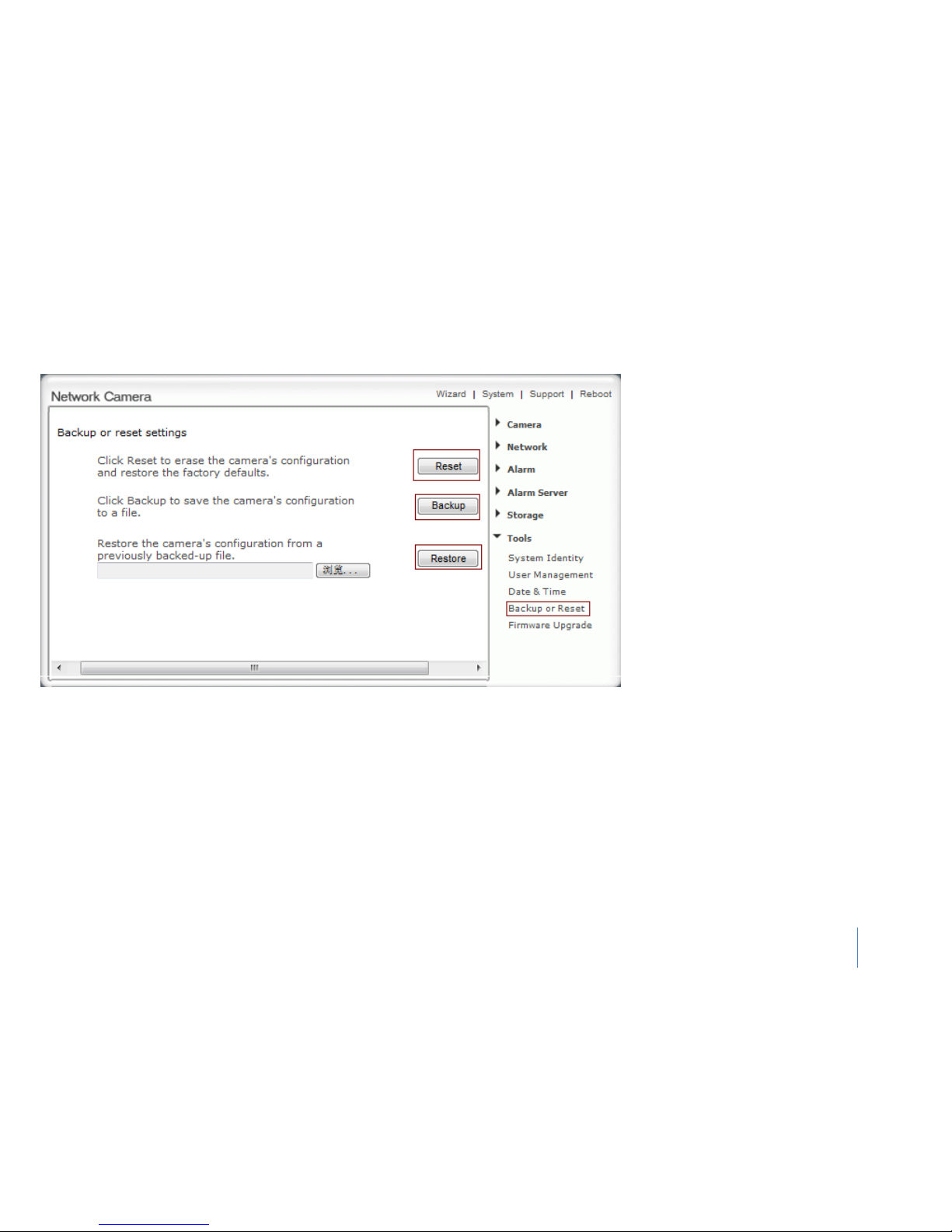
Backup or Reset
Notes: Do not turn off the power during the Reset, Backup or Restore functions since this might
corrupt the camera’s firmware
Backup or reset settings
Reset - Click “Reset” to initialize the
camera to default factory setting. All users
and settings will be lost, requiring you to
reconfigure the camera.
Backup - Click “Backup” to backup the
current configuration of the camera for
future reference.
Restore - Click “Browse” to search for a
backup configuration you wish to upload to
the camera, and then click “Restore”.
Tips: The camera can also be reset to the
default settings by pressing the “RESET”
switch on the side of the camera.
Page 58
65
Tools
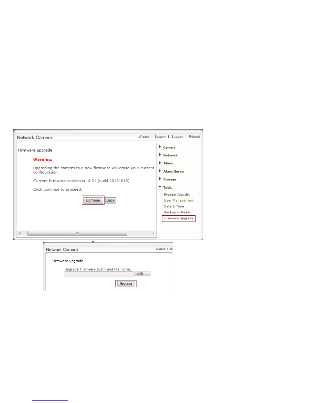
Firmware Upgrade
In order to upgrade your camera’s firmware
you first need to download this firmware from
Network Camera Technical Support Site.
1) Click “Continue”.
2) Click “Browse...” to search for the newest
Firmware you downloaded, and then Click
“Upgrade”.
IMPORTA NT:
Do not unplug or power off the camera while the
upgrade is in progress.
Page 59
66
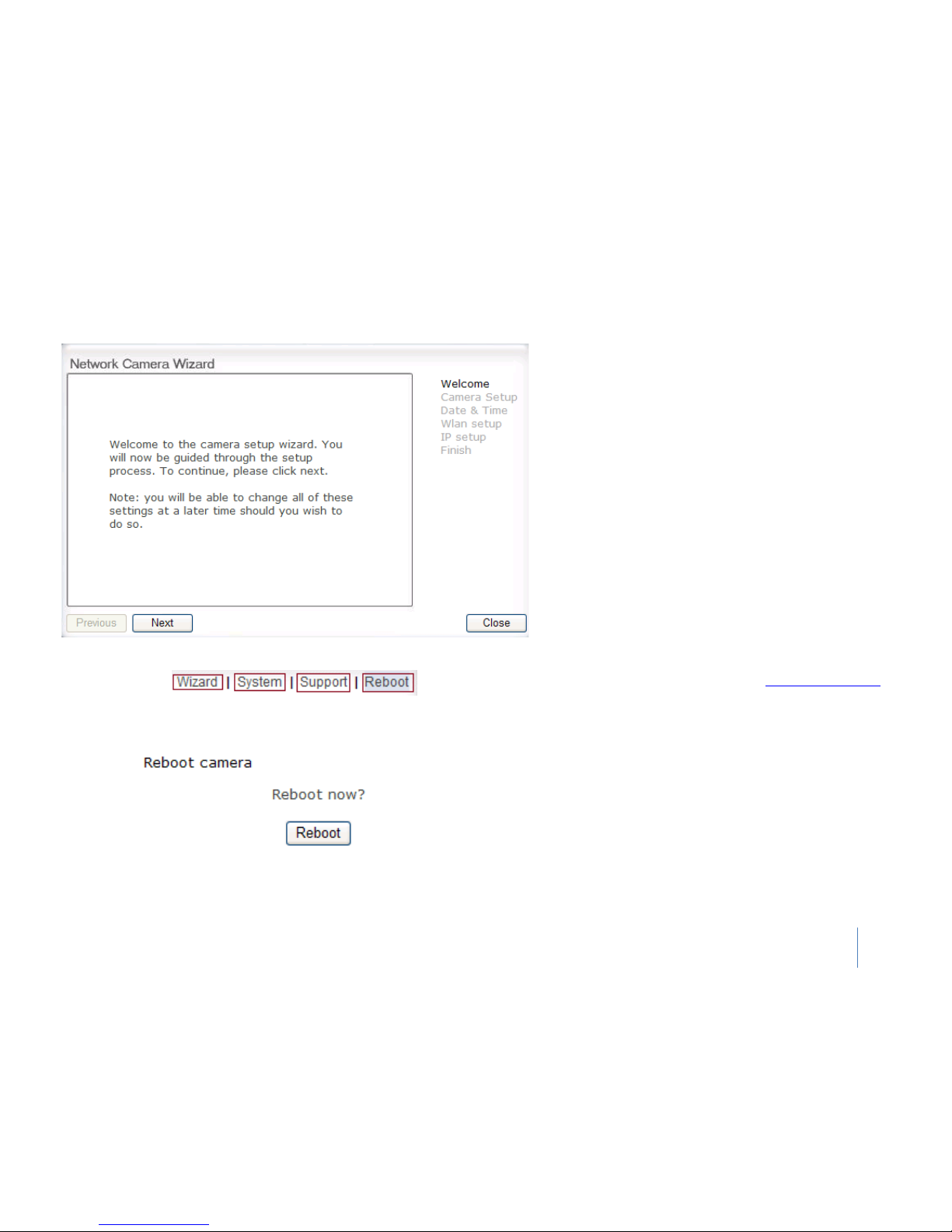
Wizard, system, support & Reboot
Wizard
In order to facilitate the setup of the camera there is a
Wizard that helps non technical users setup the camera
easily. Click on Wizard at the top of the window to launch
the wizard.
The Quick setup interface will pop up. Follow the simple
instructions on the screen and enter the required details,
clicking next to proceed to the Next page.
System
Click System to see over system information about your
camera. The data of the software activity of the camera
and recorded in here. It includes data that are useful
when a problem occurs. (click here
system information to
find details)
Support
Click Support to see the support information
Reboot
Click Reboot to restart the camera. Rebooting the camera
will retain all the settings and configurations.
Page 60

67
ADVANCED SETTINGS
Port Forwarding
The UPnP Setup of camera show a method of Port Forwarding(see page 40 for details), but some routers maybe can’t support UPnP Port
Forwarding, therefore, users need to configure Port Forwarding manually.
Firewall security features built into the router may prevent users from accessing the camera over the Internet. The router connects to the
Internet over a series of “ports”. The default ports used by the camera are usually blocked from access over the Internet, therefore, these ports
need to be made accessible. This is achieved using the Port Forwarding function on the router. The ports used by the camera must be opened
through the router for remote access to your cam
era. Check your router’s user manual for specific instructions on how to open and route ports
on you router.
Important: Some ISPs block access to port 80 and other commonly used Internet ports. Check with your ISP in order to open the appropriate
ports. If your ISP does not pass traffic on port 80, you will need to change the camera’s default port number from 80 to a different number such
as 9000.
Viewing Your Camera
To access the camera from a computer on your local network, simply enter the IP Address of the Camera followed by a colon and the camera’s
port number. It is not necessary to enter the colon and port number if you are using the camera’s default port 80.
To access the camera from the internet, type the external IP Address of the router,
followed by a colon, and the port number of your camera
(e.g., Http://210.118.166.68:9000).
Page 61
68
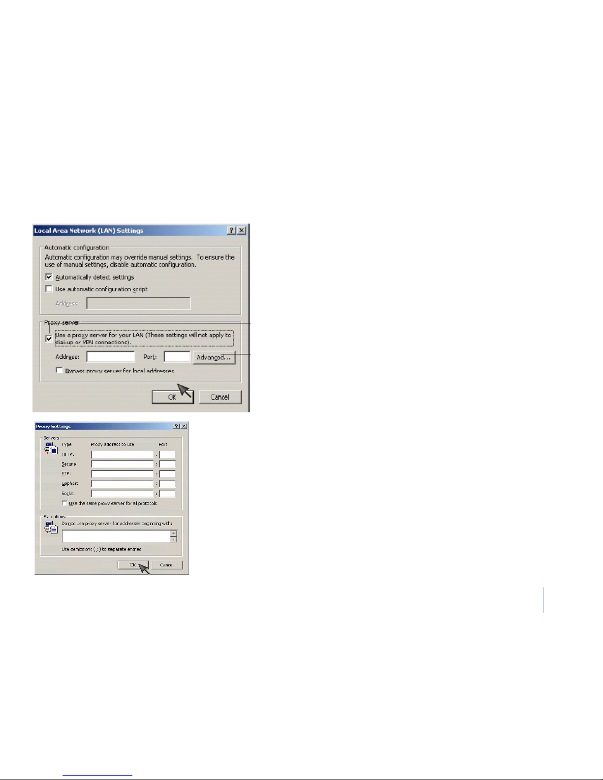
Proxy Server Setting
A proxy server may prevent you from connecting to the camera in some corporate
environments. The web browser can set up the IP address communication without
using a proxy server. Consult your ISP or network administrator for further details.
1. Start Internet Explorer.
2. Select [Tools] –> [Internet Options...] –> [Connections] tab and click [LAN
Settings].
Verify that the Use a proxy server check box is not checked. When checked, click
[Advanced...].
When not checked, click [Cancel]. Your proxy server settings should not cause any
problems.
Notes: A proxy server is generally used to maintain security on a network when
connected to the internet. The proxy server may cause lack of image quality and
delays in refresh intervals. Consult your ISP or network administrator for further
details.
3. Enter the IP address of your camera into the Do not use proxy server for
addresses beginning with data field
4. Click [OK] on all of the opened windows.
Page 62

70
Specification
Camera
Wireless LAN
(Optional)
Image device 1/4" CMOS Wireless technology IEEE802.11b/g/n
Pixels 310000 Frequency 2.412-2.462GHz
White Balance Auto Transmission speed
54Mbps/22Mbps/11Mbps/5.5Mbps/2M
bps/1Mbps (Auto Switch)
Exposure mode Auto Security
WEP (64/128 bit), WPA-PSK(AES/TKIP),
WPA2 -PSK(AES/TKIP)
Gain Auto
External Port
Viewing angle Horizontal:100°, Vertical:75° Built-in microphone Electret Condenser Microphone
Focal length f=2.5mm Audio output Yes (2 way audio)
Aperture F2.0 SD slot Yes
Min.llumination 1.0 Lux Digital I/O 1 input, 1 output
Network
General
Image compression MPEG-4 MJPEG Power requirements DC 12V
Image resolution
640x480(VGA),320x240(QVGA),
160x120(QQVGA)
Power consumption
Power over Ethernet (POE)
2.5W
Yes (optional)
Max. frame rate 30fps @640x480 Operating temperature -5 to +45 °C (+22 to +113 °F)
Audio compression
AMR(4.75 -- 12.2Kbps),
G.726 (40/32/24/16Kbps)
Supplied accessories
AC adaptor (x1), CD-
ROM(x1 setup
program and user manual), Stand(x1),
Simultaneous viewers 16 Storage temperature -20 to +60 °C (-4 to +140 °F)
Authentication Administrator/General User (Up to 64) Operating humidity
20~80%RH(Non-condensing)
Network protocols
TCP,UDP,IP,ARP,ICMP,DHCP,DNS,HTTP,FTP,SMT
P,NTP,PPPoE,UPnP,DDNS
Storage humidity
20~95%RH(Non-condensing)
Stream type RTSP/RTP/RTCP, 3GPP, ASF, HTTP Dimensions(W x D x H) 90mm x 90mm x 90mm
Network connection Ethernet (10BASE-T/100BASE-TX) Weight 160g(Main Body)
Page 63

71
Glossary of Terms
1. Network Camera: A stand-alone device which allows users to view
live, full motion video from anywhere on a computer network, even
over the Internet, using a standard web browser.
2. JPEG: A standard image format, used widely for photographs, also
known as JPG.
3. IEEE 802.11b/g: The specifications developed by the IEEE for
wireless network technology. It provides 11 Mbps transmission in the
2.4GHz band usage.
4. WEP: Wireless Equivalent Privacy. A security protocol for wireless
network defined in the IEEE 802.11b/g standard. WEP aims to provide
security by encrypting data over radio waves so that it is protected as
it is transmitted from one end point to another.
5. AdHoc Mode: A wireless network system in which devices
communicate directly with each other, without the use of a wireless
router.
6. Infrastructure Mode: One of the wireless network system in which
devices communicate with each other by first going through the
wireless router.
7. IP Address: The unique 32 bit number assigned to each computer
connected to the Internet. IP numbers are used by the TCP/IP protocol
to route packets of data to their destinations.
8. TCP/IP: The collection of "protocols" underlying the functioning of
the Internet. Each computer connected to the Internet is identified by
a unique IP Address.
9. SMTP: Simple Mail Transfer Protocol.
10. FTP: File Transfer Protocol. Network cameras equipped with an
embedded operating system, such as Linux, can use FTP to send
images to a website.
11. DHCP: Dynamic Host Configuration Protocol is a set of rules used
by communications devices such as a computer, router or network
adapter to allow the device to request and obtain an IP address from a
server which has a list of addresses available for assignment.
12 UPnP: Universal Plug and Play is an architecture for pervasive
peer-to-peer network connectivity of intelligent appliances and
wireless devices.
13. DDNS: DDNS is a method of keeping a domain name linked to a
dynamic IP address with your Network Camera. You can set up your
DDNS service and the device will automatically update your DDNS
server each time it alter a different IP address.
14. Time server: A time server consists of a computer networking
device that reads the actual time from a reference clock and
distributes this information to its clients using a computer network.
15. WPA: Wi-Fi Protected Access (WPA and WPA2 ) is a class of systems
to secure wireless (
Wi-Fi) computer networks. WPA implements the
majority of the
IEEE 802.11i standard, and was intended as an
intermediate measure to take the place of WEP while 802.11i was
prepared.
Page 64
72
IPCAM 201012(V4.21)
 Loading...