

OrangeRx TX6i Instruction Manual

INSTRUCTION MANUAL
6 CHANNEL TRANSMITTER

2
6 CHANNEL TRANSMITTER
DIGITAL PROPORTIONAL RADIO
CONTROL SYSTEMPROGRAMABLE SYSTEM
Introduction
Thank you for purchasing our product, an ideal radio system for beginners or experienced users
alike. Read this manual carefully before operation in order to ensure your safely and the safely of
others or the safe operation of your system. If you encounter any problem persists, contact your
local deal or visit our service and support website for www.hobbyking.com
Safely
1. Safely Symbols
Pay close attention to the following symbols and their meaning. Failure to follow these warning
could cause damage, injury or death.
DANGER – Not following these instructions may expose the user to serious injuries or death
WARNING – Not following these instructions may expose the user to serious injuries
ATTENTION – Not following these instructions may expose the user to minor injuries and
even to serious injuries
Do not use at night or during a lightening storm, as bad weather will adversely affect the
control of your system
Make sure that the motors are all moving the same direction as the operating direction
The shutdown sequence: 1. Disconnect the receiver battery 2. Switch off the transmitter.
Failure following this sequence may result in uncontrolled movement and damage to the
system.
Do not use the product when visibility is limited
Interference may cause loss of control. To ensure the safely, do not operate in the followingplaces:
Near any site where other radio control activities may occur
Near high power lines or communication broadcasting antennas
Near any site where overcrowded and traffic congestion
On water or on boats and ships
Do not use this product when you are tired, uncomfortable or under the influence of alcohol or
drugs.
Never grip the transmitter antenna during operation. It significantly degrades signal quality
and strength and may cause loss of control
Safety guide
PROHIBITED
MANDATORY

3
6 CHANNEL TRANSMITTER
DIGITAL PROPORTIONAL RADIO
CONTROL SYSTEMPROGRAMABLE SYSTEM
Do not touch any part of the model that may generate heat during operation. The engine,
motors and speed control may be hot and cause injury.
Do not grasp the transmitter’s antenna during flight. It may be degraded the quality of the
radio frequency transmission.
Make sure the model flies within a certain distance range.
FCC statement
Note:
This device complies with part 15 of the FCC Rules.Operationis subject to the following two
conditions: (1) this device may not causeharmful interference, and (2) this device must
accept any interference received, including interference that may cause undesiredoperation.
4
6 CHANNEL TRANSMITTER
DIGITAL PROPORTIONAL RADIO
CONTROL SYSTEMPROGRAMABLE SYSTEM
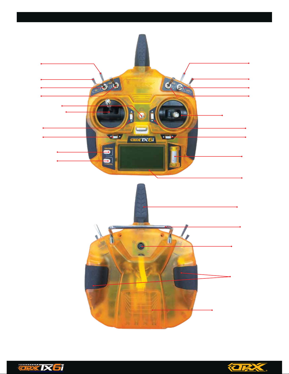
Transmitter Overview
S6
S5
S1
S2
Trim Trim
TrimTrim
Lanyard hook
Throttle/Rudder
Binding key
Cancel key
Elevator/Aileron
Wheel
LCD
Antenna
Handle
Trainer port
Grip
Bettery compartment
S8
S7
S4
S3
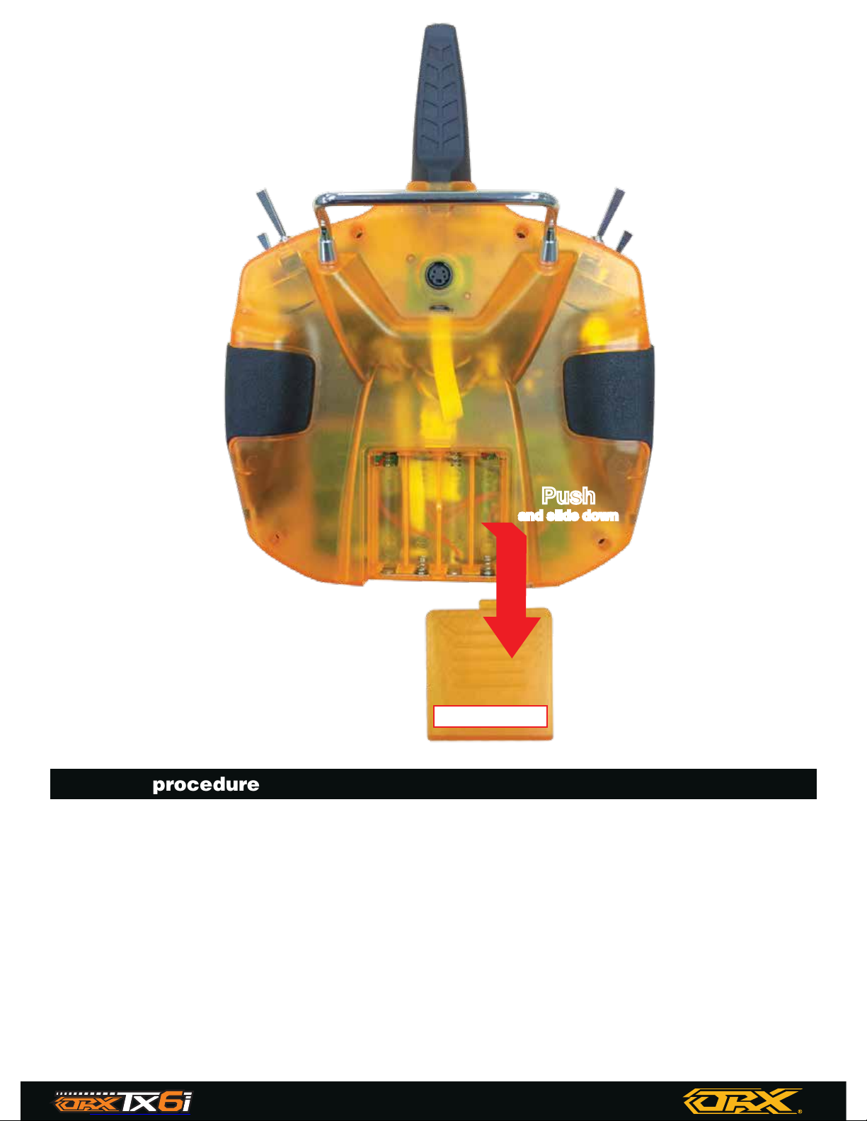
Installation and removal of the transmitter battery
The T6i transmitter is designed to work with four x (LR6) AA alkaline dry cell batteries
Binding procedure
1. Install a bind plug into BIND connector. In case if you want to disable telemetry function on the
receiver, install second bind plug into THRO connector.
2. Apply power to the receiver. It can be from 3.7 to 9.6 volts DC. Please refer to indicator on the
receiver for the correct pinout (GND, VCC, SIGNAL)
3. You will see the orange LED rapidly blinking. That means the receiver is in Bind mode.
4. Press and hold the binding key and turn on the transmitter. (Or, turn on the transmitter, press
and hold the wheel to enter the main menu to select model setup, then choose the bind menu to
enter binding mode)
5
6 CHANNEL TRANSMITTER
DIGITAL PROPORTIONAL RADIO
CONTROL SYSTEMPROGRAMABLE SYSTEM
(Take ORX receiver as example)
Battery cover
Push
and slide down
Push
and slide down

Airplane
Servo setup
Servo Setup adjusts the Servo Reverse, End point, Sub-Trim for all six channels.
Press and hold the Roller button to main menu and select “Servo Setup”
Press the Roller button to select “Reverse”, “End point” and “Subtrim”
Reverse
The Reverse function is used to correct a servo or motor’s direction in relation to the systems
controls. For each channel the user can toggle a reverse state based on demand.
This Reverse function individually reverses the direction of operation of servos on the 6 channels.
This menu contains 6 check boxes, one of each channel.
Setup:
1. Press the Roller button to select channel
2. Move the Roller button to left or right to select “Nor” (Normal) and “Rev” (Reverse)
3. Press and hold the Roller button to save and exit
4. OR press the cancel key to exit without saving
6
6 CHANNEL TRANSMITTER
DIGITAL PROPORTIONAL RADIO
CONTROL SYSTEMPROGRAMABLE SYSTEM
5. The system will display “RX Binding..”. After successfully binding, the transmitter will automati
cally exit this binding menu.
6. Remove the bind plug(s) from the BIND on the receiver
NOTICE:
Remove the bind plug to prevent the system from entering bind mode the next time the power is
turned on.
Sometimes servo inputs or ESC-s with high input load can cause receiver binding in “No teleme-
try” mode. During this binding you will see both orange and red LED blinking. If you want to have
telemetry function enabled please make sure that nothing is connected to Throttle channel during
binding procedure.
Setup:
1. Press the Roller button to select channel
2. The right-side value represents high limit / The left-side value represents low limit. Move the
stick to the desired low or high value.
3. Move the Roller button left or right to change the value.
4. Press and hold the wheel to save an exit
5. Or press the cancel key to exit without saving.
Setup:
1. Press the Roller button to select channel.
2. Move the Roller button left or right to change the subtrim’s value.
3. Press and hold the wheel to save an exit
4. Or press the cancel key to exit without saving.
7
6 CHANNEL TRANSMITTER
DIGITAL PROPORTIONAL RADIO
CONTROL SYSTEMPROGRAMABLE SYSTEM
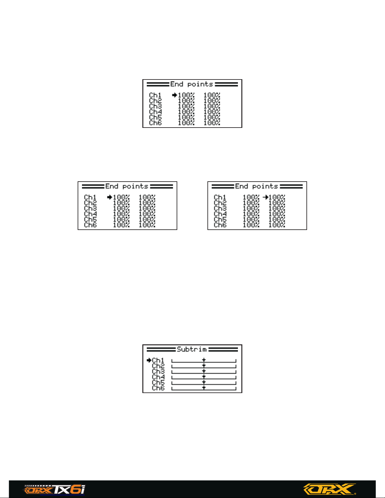
End points
End points controls the low and high travel limits for each servo. For each channel the user can set
the low and high limits. This ensures that the channel date for the servo is consistent with structur-
al design and performance requirements to ensure the best results. Adjustment can be made for
any channel.
Subtrim
Subtrim controls the structure and angle different of each channel on the servo. It individually
adjusts the center position of each servo of the 6 channels. This is particularly useful when the
servo mechanics can’t allow very fine tuning.
Point to high value Point to low value
8
6 CHANNEL TRANSMITTER
DIGITAL PROPORTIONAL RADIO
CONTROL SYSTEMPROGRAMABLE SYSTEM
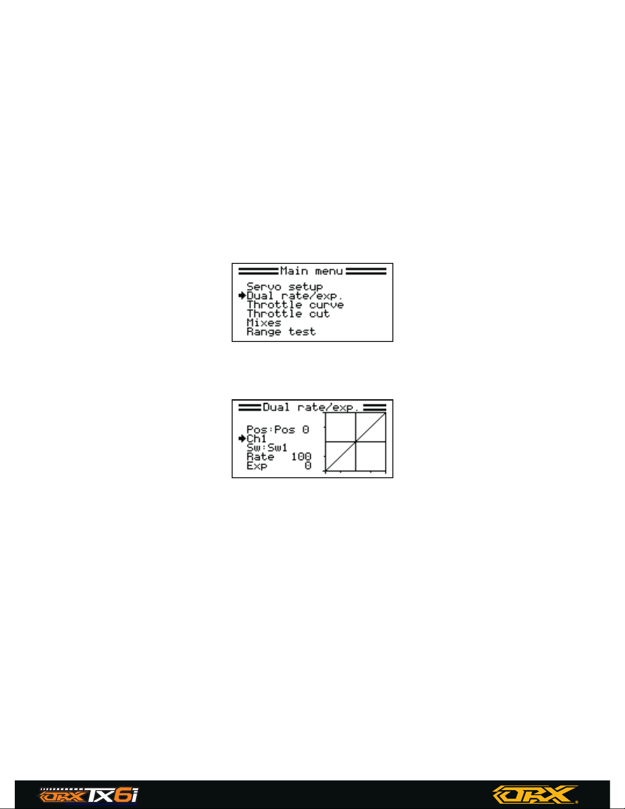
Dual rate/exp.
This function is use to add a curve to the channels input. This means that the ratio of stick to
channel movement can be changed in order to add or remove sensitivity at different parts of the
sticks range of motion. It can available on the aileron, elevator and rudder channels. This function
sets the rate and exp. for channels 1, 2 & 4 and the switches from Sw 1 to 8, Disable and ON
Rate – Adjust the slope of the curve. The smaller is the slope, the shorter is the throw of the corre-
sponding servo
Exp – Adjust the linearity curve of the sticks and knobs. A value of 0 corresponds to a perfectly
linear curve. A positive value increases the sensitivity near the neutral position and decreases it on
the extreme sides.
Throttle curve
This function enables the user to adjust the ratio between stick and servo movement using linear
or nonlinear curves.
This is useful to change how the throttle reacts at different stick positions. The 5 points (L, 1, 2, 3,
H) of throttle curve can be adjusted from 0% to 100%. The horizontal dotted line displays in real
time the throttle stick position. The vertical dotted line displays in real time the position of the
throttle output after the throttle curve function has been applied. For example, having a smaller
throttle change when the stick is between 0-30%, then a larger throttle change between 30% and
100%. If your models throttle is not linear, it is possible to use this function to create a more linear
movement.
Setup:
1. In main Menu, Press the Roller button to select “Dual rate/exp”
2. Press the Roller button to select Channel / Switch / Rate / Exp
3. Move the Roller button left or right to select value
4. Press and hold the wheel to save an exit
5. Or press the cancel key to exit without saving.
 Loading...