


0.1uF 0.1uF
C4
C1
0.1uF
Y1
C2
Instructions
C3
13
AREF
GND
12
11
10
9
⁓
DIGTAL
L ON
22pF
8
⁓
⁓
7
PWM–
RESET
16.000
6
⁓
⁓
⁓
Build
5
4
3
2
⁓
1
0A5
TX
RX
9-12V
0.1uF
RESET
3.3V
5V
GND
GND
Vin
0.1uF
ANALOG INPOWER
A0
A1
A2
A3
ICSP
22pF
A4

Check contents before you build!
1x
Orangepip Segments PCB
1x
Tactile switch
2x
1x
16MHz crystal
1x
Red LED
2x
1x
ATmega328 Microcontroller
1x
Green LED
1x
1x
Dual in line socket
1x
6-pin dual row header
1x
8-pin single row sockets
1x
10K resistor
1x
1N4007 diode
6-pin single row sockets
2x
330R resistors
1x
7805 voltage regulator
USB socket
2x
1K resistors
1x
7133 voltage regulator
5x
Power supply jack socket
2x
47uF electrolytic capacitors
1x
PTC resettable fuse
2x
2
0.1uF ceramic capacitor
22pF ceramic capacitor

How to build your …
Orangepip Segments328
To put your Orangepip Segments328 together you will need basic soldering skills. When soldering
you should always work on a at surface in a well-ventilated environment. Make sure you have plenty
of room on your workspace.
Equipment you will need …
Soldering Iron Solder Side Cutters Snipe nose pliers Multimeter Assembly aid/
helping hand
Check your kit before starting, to make sure you are not missing any components.
The circuit diagram for your Orangepip Segments
3
1.0
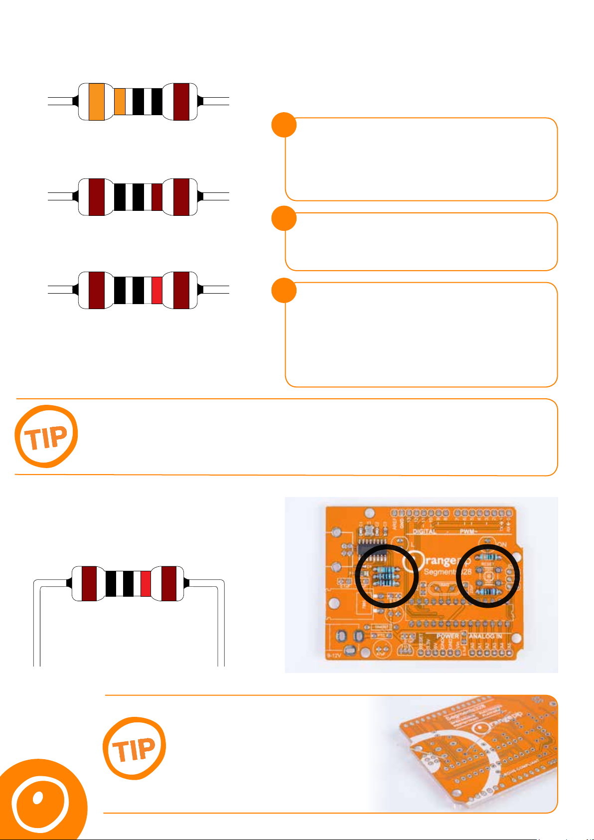
Locate the bag containing the resistors. This will include 5 pieces in total. Sort them carefully into their
respective values using the illustrations below.
There are three ways to identify the value
of a resistor:
1
330R x 2 pieces.
Orange, Orange, Black, Black, Brown
1K x 2 Pieces. Brown, Black, Black, Brown, Brown
Using a Multimeter
• Polarity doesn’t matter to the measurement.
• It removes the possibility of misreading one of the resistor
colour bands.
• It can be a quick way to check when you have multiple resistors.
2
Resistor Card
• It doesn’t need power or the Internet so you can use it anywhere
• It teaches you to read the values without the aid of any equipment
3
Online guide
10K x 1 piece. Brown, Black, Black, Red, Brown
To be 100% sure you can use a multimeter to check the value of the resistors.
It can be easy to misread a 1% tolerance brown band as the 1st digit!
SEE OUR MULTIMETER VIDEO FOR DETAILS.
1.1
Bend the resistor legs 90° and then insert each
resistor into the indicated location on the board
and solder in place
• Inputting the resistor colour bands will give you the exact value
of the resistor
• The calculations are done for you which makes it easier to use
than a resistor card.
• You just need to accurately identify the colours to get the
correct result.
Bend the legs outwards to
prevent the components from
dropping out of the PCB while
soldering.
4

2.0
Locate the crystal and place into the board.
Use the leg bending tip from earlier to keep
the crystal ush to the PCB and solder in place.
2.1
Locate the bag containing the microcontroller and the DIL socket.
The chip carrier socket is not polarity sensitive, but you will notice that there is a notch in one end.
This is used to assist with the correct placement of the Microcontroller, which is polarity sensitive.
The PCB, the DIL socket and the Microcontroller all share the notch marking to aid correct placement.
Place the correctly orientated DIL socket into the PCB and solder into place.
2.2
Next it’s the 1N4007 diode. This is the rst polarity sensitive item that we are going to add to the
board. A polarised component must be connected to the circuit the correct way round. Diodes only
allow current to ow in one direction from the anode to the cathode. We can identify the cathode by
the silver band. The PCB has a corresponding mark to match this up with.
Place the component into the PCB with
the silver band matching the marking on
the PCB and solder in place.
5

2.3
Separate the ceramic capacitors from the
other components. The 0.1uF capacitors are
marked with the number 104 and the 22pF
are marked with the number 22.
2.4
Place the 0.1uF (104) capacitors into the
marked locations on the PCB and solder in
place.
5x 2x
0.1uF 22pF
2.5
Place the 22pF (22) capacitors into the marked
locations on the PCB and solder in place.
2.6
Locate the 7805 voltage regulator (L7805CV).
Just like the diode the voltage regulator needs
to be placed in the PCB the correct way round.
The diagram on the right shows the pinout.
Output
GND
Input
6

2.7
In the image on the right you can see that the
component has been laid at against the PCB
to oer a lower prole. This can be done with
a pair of needle nose pliers or by pushing the
component into the board and applying pressure
to atten the device.
If you have any doubts about doing this,
the product can be soldered upright with
no negative eects other than an increased
height prole. If you decide to do this then
we recommend saving it until last.
2.8
Next, the tactile switch. Push the tactile switch
into the PCB. The component is not polarity
sensitive and can be inserted either way round.
The kink in the legs will ensure it stays in place
while being soldered.
2.9
Locate the 7133 regulator. This regulator is polarity sensitive and needs to be inserted into the PCB
the correct way round. The marking on the PCB is shaped to match the component. The at face
of the regulator should be facing away from the Orangepip logo towards the edge of the board.
7

2.10
Locate the PTC resettable fuse.
This component is not polarity sensitive so
place into the PCB and solder in place.
2.11
Locate the 47uF electrolytic
capacitors. These are polarity
sensitive, so you need to ensure they
are mounted the correct way round.
To assist with this the capacitors
have two indicators to help identify
the orientation. The rst is that the
positive (anode) leg is longer than the
negative (cathode). The second is
that the body is marked with a silver
line with minus signs to indicate the
negative (cathode). Match the longer
leg with the + marking on the PCB.
3.0
Locate the I/O sockets. There are 2x 6 way and 2x 8 way. The 8 way sockets are to be placed
in the ’DIGITAL’ and ‘PWM’ slots shown at the top of the picture. The 6 way sockets are to be placed
in the ‘POWER’ and ‘ANALOG IN’ slots shown at the bottom of the image.
8

3.1
Locate the ICSP 6 pin header. This is not polarity
sensitive, but you will notice that the legs either side
of the black plastic are dierent lengths. The shorter
ends should be on the underside of the boards with
the longer ends accessible from the top.
3.2
Locate the green and red LEDs. The LEDs are polarity sensitive and need to be inserted into the PCB
the correct way round. We can use a similar method to the electrolytic capacitors to determine the
correct orientation. The positive (anode) is the longer leg and the negative (cathode) is the shorter leg.
Match the longer leg with the + mark on the PCB. It doesn’t matter which LED you solder in which
location.
3.3
Locate the USB-B connector. The two larger
pins act as anchor points and ensure that the
connector can stand up to repeated insertion
and removal of the USB cable. They are also
useful to hold the connector in place during
soldering.
9

3.4
How to program
Orangepip
Segments328
with your PC
Locate the 2.1mm DC socket. Insert it into the
PCB and solder in place.
3.5
The last job is to insert the ATmega328 microcontroller into the chip carrier socket you soldered
earlier. The microcontroller is polarity sensitive. Find the end that has the notch and line this up
with the notch on the microcontroller.
Place the microcontroller gently into the socket. Ensure that the pins are lined up with those of the
socket and apply rm but even pressure to seat the microcontroller in the socket. Not applying even
pressure can cause the pins to bend out of shape and damage the microcontroller.
4.0
Your board is now complete, and you can begin prototyping.
Click here for our guide on installing the software and
uploading your rst program.
10
 Loading...