

Page 1
Manual for Tire Pressure Monitoring Systems, TPMS
1/22
To ensure correct operation and service please read these instructions before installing and
operating the TPMS
TPMS Manual
TABLE OF CONTENTS
TIRE PRESSURE MONITORING SYSTEMS, TPMS .................... 2
NOTICE ........................................................................................ 2
SPECIFICATIONS OF TPMS ....................................................... 3
SYSTEM INSTALLATION ............................................................ 3
ACCESSORIES FOR TIRE PRESSURE MONITORING SYSTEM ............. 4
DISPLAY UNIT INSTALLATION .................................................. 4
WIRELESS TRANSMITTER SENSOR INSTALLATION .............. 5
SYSTEM OPERATION ................................................................. 9
SYSTEM ALARM .......................................................................... 9
SETUP METHOD .......................................................................... 9
Choosing preferred Pressure Units and Temperature Units ......................................... 10
Standard Front/Rear Tire Pressure Setting ..................................................................... 11
Tire Over Temperature Warning ....................................................................................... 11
Alarm Instruction ................................................................................................................ 12
RESET FOR TIRE CHANGES AND ROTATION ........................ 13
Mode 1: Front to Rear tires exchanged ........................................................................... 14
Mode 2:Tires diagonal exchanged ................................................................................. 15
Mode 3:Front tires diagonal exchanged, and Rear tires parallel changed to Front .. 16
Mode 4:Random re-position tires ................................................................................... 17
Mode 5: Single sensor replaced ..................................................................................... 18
APPENDIX .................................................................................. 19
ANNEXES ................................................................................... 19
WARRANTY POLICY ................................................................. 20
TROUBLESHOOTING GUIDE .................................................... 21
To ensure correct operation and service please read these
instructions before installing and operating the TPMS
Page 2

Manual for Tire Pressure Monitoring Systems, TPMS
2/22
Tire Pressure Monitoring Systems, TPMS
Tire Pressure Monitoring Systems (TPMS) improves safety while driving. Once installed in your
vehicle, the system will automatically monitor your tires in real-time for pressure and
temperature. When any tire’s pressure and/or temperature appear abnormal, the system will, in
real-time, transmit signals to active an alarm and show a digital figure to warn the driver of a
problem. The system aids safety, can extend the tire life and help reduce fuel consumption.
NOTICE
FCC Notice
This device complies with Part 15 of the FCC Rules. Operation is subject to the following two
conditions: (1) this device may not cause harmful interference, and (2) this device must accept
any interference received, including interference that may cause undesired operation.
This equipment has been tested and found to comply with the limits for a Class B digital device,
pursuant to Part 15 of the FCC Rules. These limits are designed to provide reasonable
protection against harmful interference in a residential installation. This equipment generates
uses and can radiate radio frequency energy and, if not installed and used in accordance with
the instructions, may cause harmful interference to radio communications. However, there is
no guarantee that interference will not occur in a particular installation.
If this equipment does cause harmful interference to radio or television reception, which can be
determined by turning the equipment off and on, the user is encouraged to try to correct the
interference by one or more of the factoring measures.
Reorient or relocate the receiving antenna.
Increase the separation between the equipment and receiver.
Connect the equipment into an outlet on a circuit different from that to which the receiver
is connected
Caution: Any changes or modifications in construction of this device which are not expressly
approved by the party responsible for compliance could void the user’s authority to operate the
equipment.
To comply with the FCC RF exposure compliance requirements, this device and its antenna
must not be co-located or operating to conjunction with any other antenna or transmitter.
System Scope of Use and Warnings
Tire Pressure Monitoring System, TPMS
This system is a sensing device designed to measure and display tire operation and / or
activate an alert to the driver when pressure and temperature irregularities are detected. It is
the responsibility of the driver to react promptly and with discretion to alerts. Abnormal tire
inflation pressure should be corrected at the earliest opportunity.
Caution: The system is wireless RF product; therefore, it may not receive signal due to
interference environment or incorrect operating or installation. When the system continually
cannot receive signal from one of the tire sensor more than 20 minutes since the system be
switched on, the system will show “ E2 ”. In this case, it may cause by a RF interference
environment and driver needs to drive the vehicle to other place. If the display still cannot
receive any correct signal from tire sensor, then, driver needs to find a nearby qualified tire
maintain service for checking and maintain. It may cause by a tire sensor damaged or battery
power consumption is low (the battery consumption will be lower than under normal using
condition due to sensors need to send warning signal continually to driver) . If the system
continually cannot receive signal from any sensors more than 20 minutes, the system might
damaged and will show “E1”. Driver needs to drive to other place (there might be a
interference nearby) or send the system to agent for repair
*System Installation and Usage
Use of the TPMS requires that qualified personnel according to the instructions here have
properly installed it. This system is suitable for use on a passenger car, SUV and 4X4 tires,
with up to maximum cold inflation pressure of 74 Psi (Gauge), below instruction is Gauge value
mentioned.
Page 3
Manual for Tire Pressure Monitoring Systems, TPMS
3/22
*Reacting to Alerts
When an alert or warning is received, reduce vehicle’s speed and proceed to a safe location to
stop where the tire can be inspected and /or serviced.
The low-pressure alert indicates that the air pressure has dropped to a selected minimum and
a high-temperature alert indicates that the temperature of the tire content has surpassed the
threshold value set. When the battery voltage icon flash, it means the battery voltage of vehicle
is below battery voltage default (11v).
*Use of Chemicals
Temporary resealing or re-inflation products containing internal sealants or propellants in any
tire assembly may adversely affect the operation of the sensor/transmitter.
Specifications of TPMS
RECEIVER SPECIFICATIONS
Operating voltage
12V DC
Operating current
< 200mA
Storage temperature
-30°C to 75°C
Operating temperature
-25°C to 75°C
SENSOR AND TRANSMITTER SPECIFICATIONS
Storage temperature
-40°C to 125°C
Operating temperature
-40°C to 125°C
Operating humidity
Max 95%
Operating frequency
433.92MHz ± 50kHz
Pressure monitoring range
0~74 psi
Pressure reading accuracy
At Normal condition
± 1psi at normal pressure range
Temperature reading accuracy
± 4°C in normal environmental condition
Transmission power
Max 75 dBμV/m
Battery
3V
Sensor weight
28g ±3g
System Installation
There are two parts of system installation
1. Setting up the display unit in the vehicle
2. Installing the transmitter unit sensor in each tire.
We strongly suggest installing the display unit first, and then install the tire transmitters.
Note: Warranty including “Wireless Display Unit and Wireless Transmitter Sensor and Power
Connection cable”, not including other accessories.
When remove transmitter sensors to different tires and replace new transmitter sensors,
suggest to change all of the valve steams and screws.
Page 4
Manual for Tire Pressure Monitoring Systems, TPMS
4/22
Accessories for Tire Pressure Monitoring System
NO.
Accessory Name
Quantity
A
Wireless Receiver and Display Unit
1
B
Velcro for Display
1 set
C
Power Connection for Cigarette Lighter
1
D
Wireless Transmitter Sensor with Valve Stem
4
E
Valve Nut
4
F
Nut for stand
1
G
Base (for display unit)
1
H
Windshield holder
1
I
3M Double-Coated Adhesive
1
Caution: the power connection is NOT COMPATABLE with USB interface; please do not plug
in any USB devices.
Display Unit Installation
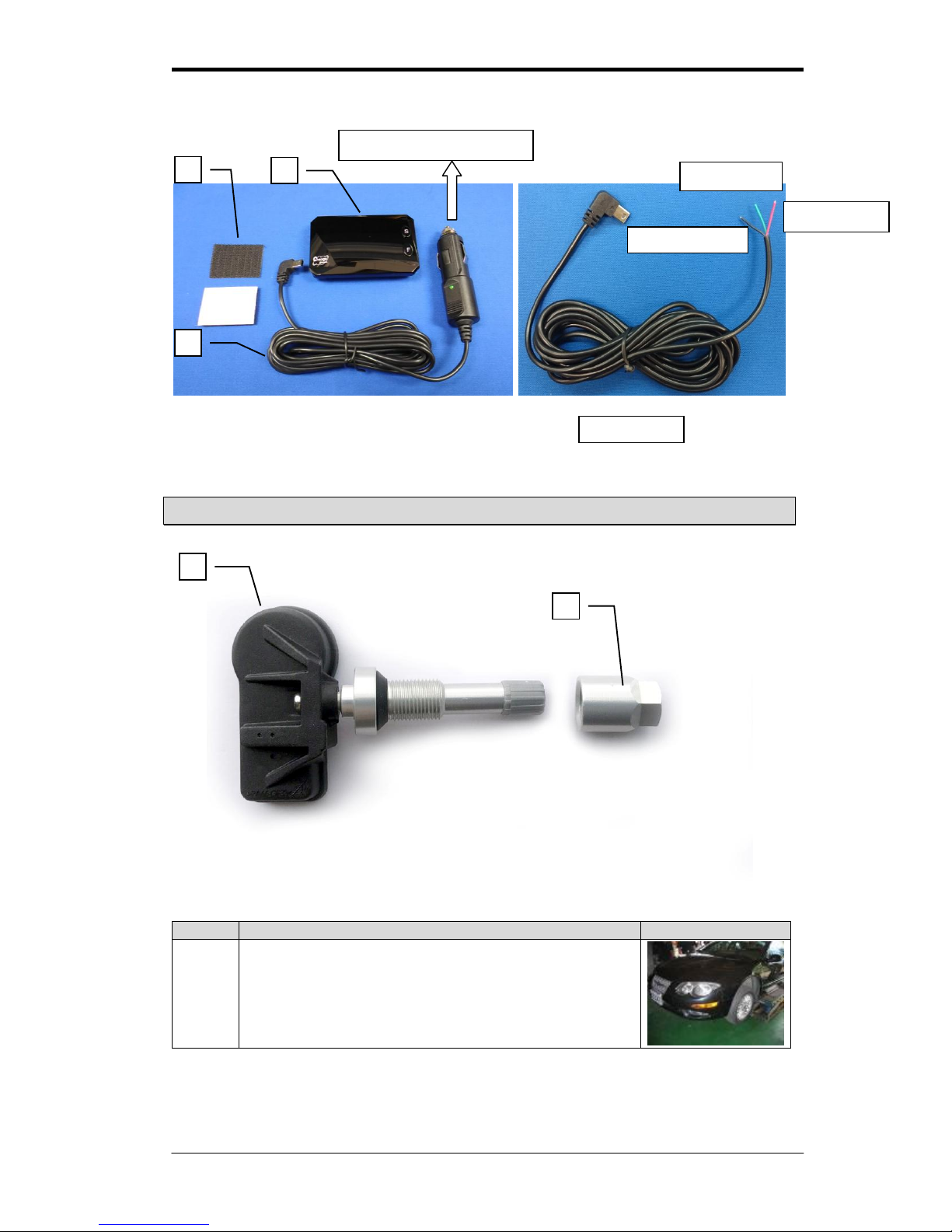
1. Plug in one side of C the power cable connection into A the display located on the side.
2. Connect the power cable into the vehicle’s cigarette lighter socket for power connection.
(or cut the cigar jet. plug the power cable with ACC, Positive, Negative into fuse box)
Note: Plugging the power cable with ACC, Positive, Negative into fuse box, the LED light will
turn on only when ACC is on and the LED light will be off when ACC is turned off.
3. Install the display unit in front of driver at an appropriate position.
Stick the Velcro B into the bottom of the display unit A, and Stick the unit into the
convenient place.
4. After set up the monitor please take off the protection film from the panel of monitor.
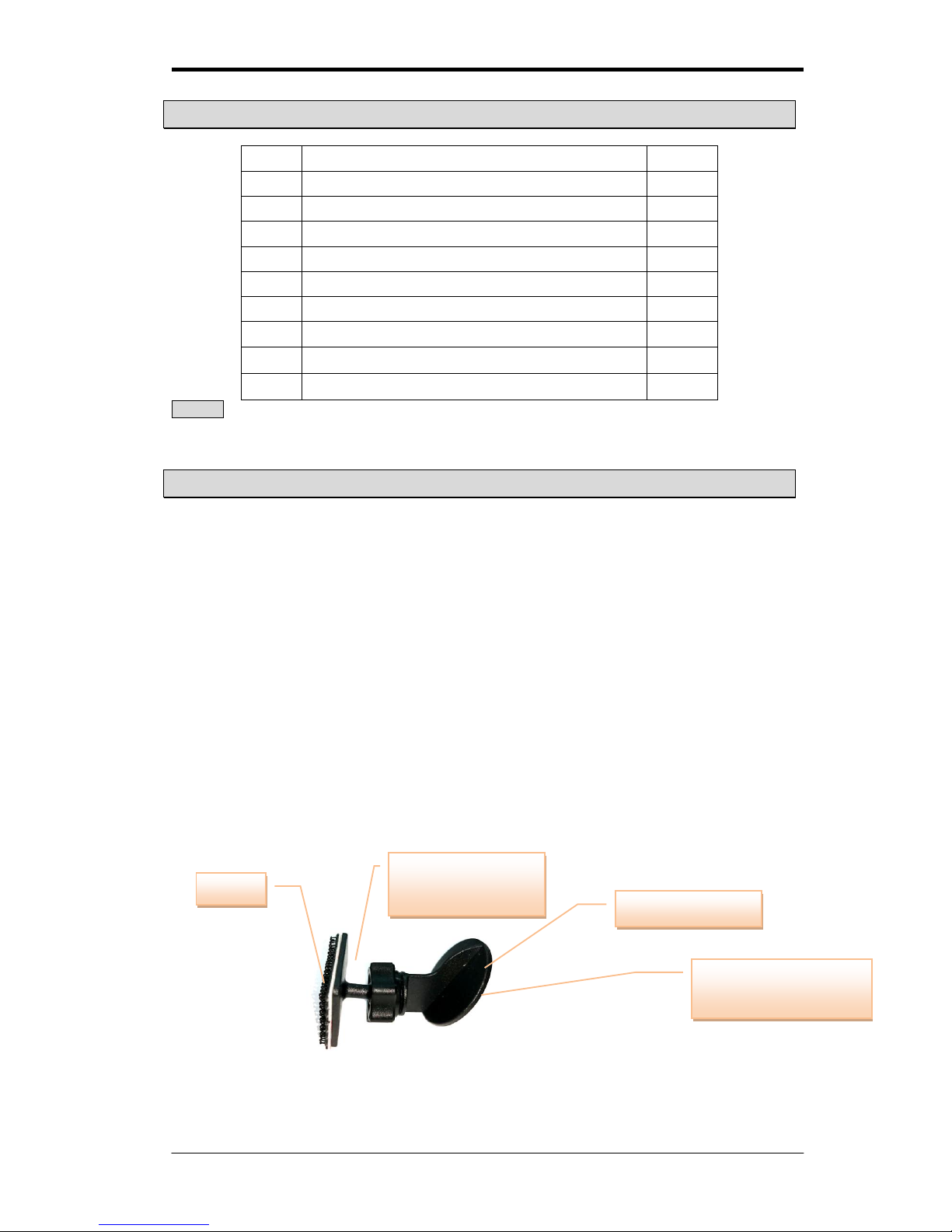
Installing steps:
Step1: Take off white film of Velcro (B) and adhere to Base (G). Adhere the other Velcro (B) to
the back of the Wireless Receiver and Display Unit.
Step2: Screw Nut for stand (F) to the Base (G).
Step3: Attach the head of base (G) to the windshield holder, and screw the nut tightly.
Step4: Use any side of 3M double-coated Adhesive (I) to windshield holder, another side is
adhered to windshield.
3M double-coated
adhesive
Velcro
Base
(for Display Unit)
Windshield holder
Page 5
Manual for Tire Pressure Monitoring Systems, TPMS
5/22
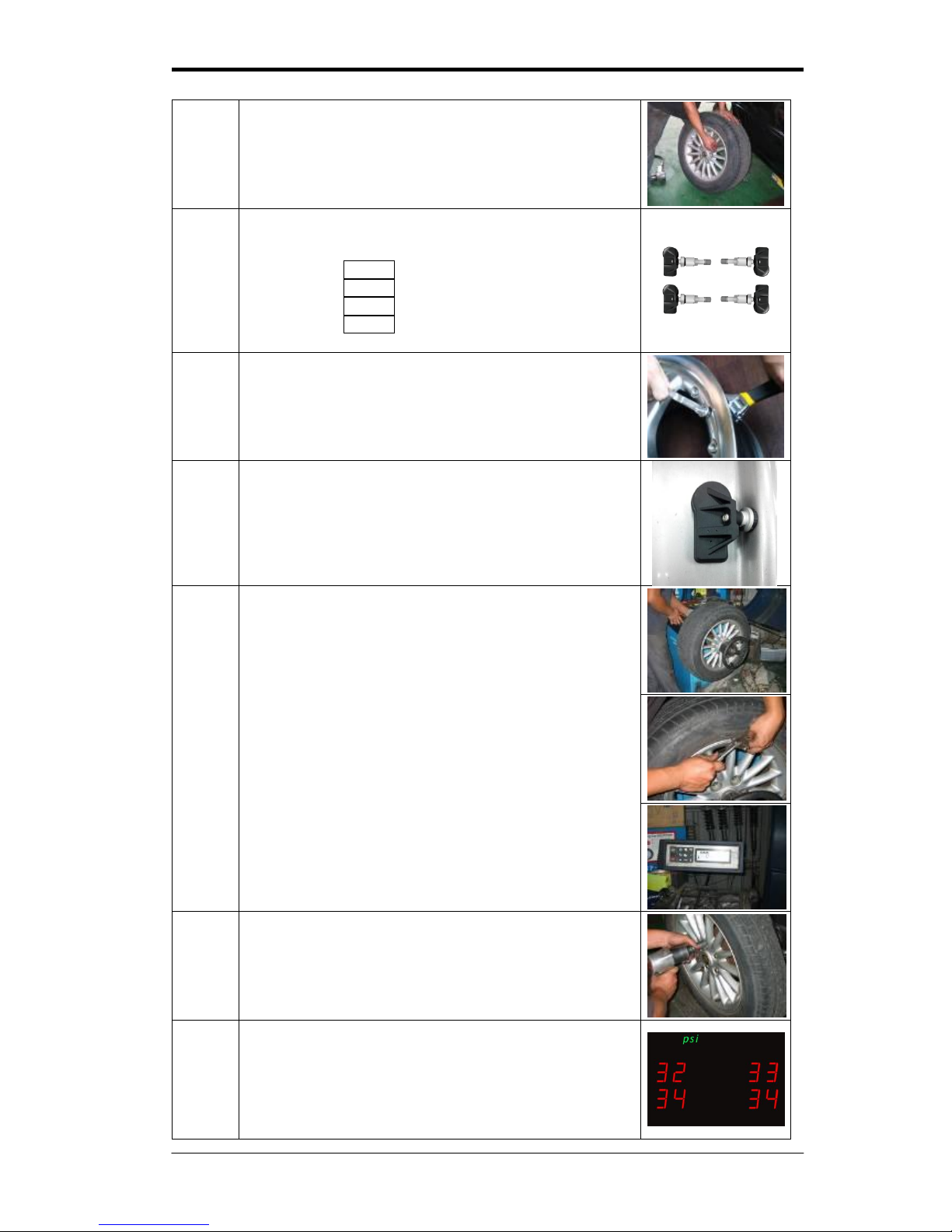
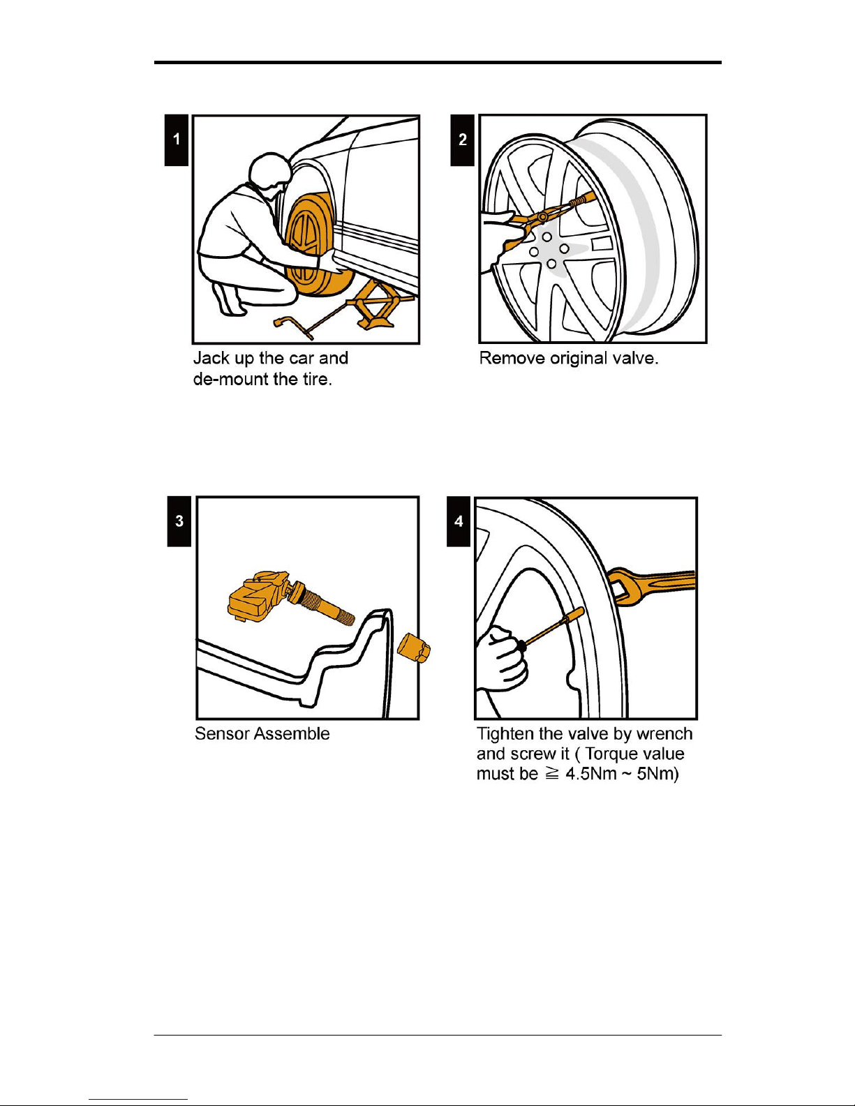
Wireless Transmitter Sensor Installation
Step
Operation Process
Photograph
1
Use a jack to raise the vehicle and place jack stands
underneath the vehicle for safety. Refer to vehicle owner’s
manual for full service advice. Seek the assistance of a
qualified motor mechanic if required.
Positive (Red)
ACC (Green)
Power Cable
Negative (Black)
Plug into car power socket
A B C E D
Page 6
Manual for Tire Pressure Monitoring Systems, TPMS
6/22
2
Take off the tires and bleed the air. Then take off the air
valve of the tire from the wheel. (NOTE: You must change
the valve to TPMS valve). This part of the process will
normally require the service of a tire fitting service or
mechanic.
3
Recognize the number on each sensor (D) with position of
tire on the vehicle. (VERY IMPORTANT)
a. RF – 1 = Right Front, No. 1
b. RR – 2 = Right Rear, No. 2
c. LR – 3 = Left Rear, No. 3
d. LF – 4 = Left Front, No. 4
4
Set up the new TPMS special valve (E) in the wheel.
Use wrench to fix the valve, and then tighten nut to
40~45kgf-cm (4~4.5Nm).
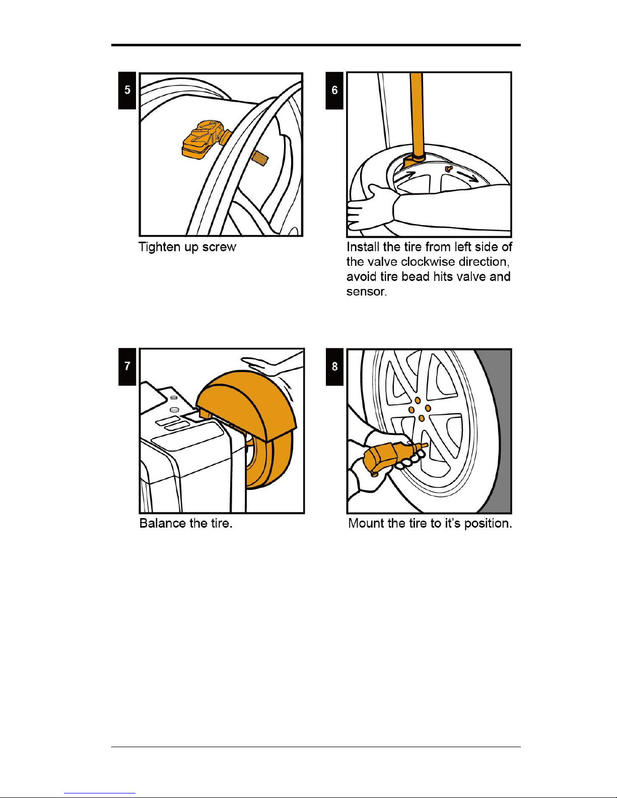
5
Clean inside the tire to prevent the tire from damaging the
transmitter sensor.
6
Inflate the tires.
Balance the tire
a. Balance tires using a balance machine
b. A lead tire weight may need to be added for balancing.
c. Balance until the tire balance shows balance as “OK”
The Steps above will require the assistance of a tire fitting
service or a mechanic. It is important that the wheels are
balanced after the fitting of the TPMS sensors in order to
ensure the safe operation of the tire when refitted to the
vehicle.。
7
Set up the other three tires in the same manner.
8
Turn the ignition key of the vehicle until the power is
activated on the cigar lighter, this may be first or second
position depending on the car manufacturer. The in-car
display will be activated.
The function button of the display unit can be switched to
pressure or temperature depending on the customer’s
need.
Page 7
Manual for Tire Pressure Monitoring Systems, TPMS
7/22
Page 8
Manual for Tire Pressure Monitoring Systems, TPMS
8/22
Page 9
Manual for Tire Pressure Monitoring Systems, TPMS
9/22
System Operation
After the system is installed, it will automatically monitor the tire pressure and temperature.
Once the ignition is turned on, and the vehicle is in motion, the display will show the real-time
tire pressure and temperature individually.
System Alarm
The alarm system will start, if tire pressure is too low, and if tire temperature is too high, the
alarm system will start too, and tire pressure will show on display. If high tire temperature and
low tire pressure situation happen at the same time, the system will show low tire pressure at
first and then show tire temperature, both of tire pressure and temperature will show on the
screen for six seconds by turns.
The alarm will keep making sound till turning off alarm system or solving abnormal situation,
and below the manual will explain operation process.
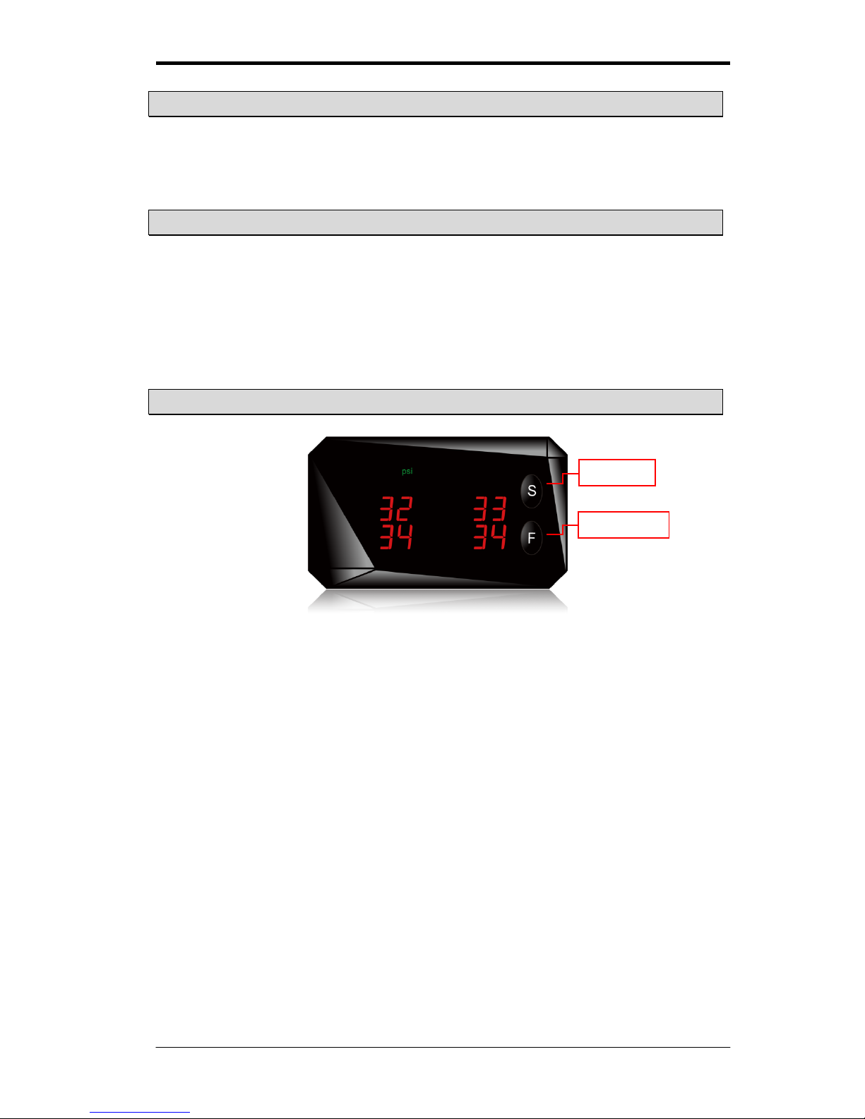
Setup Method
The driver can follow the steps to adjust the system of pre-loaded values
※Notice: The system has been pre-set with alert figures. If the driver wants to change the
figure, then follow the professional tire technician’s instruction.
Set key
Function Key
Page 10
Manual for Tire Pressure Monitoring Systems, TPMS
10/22
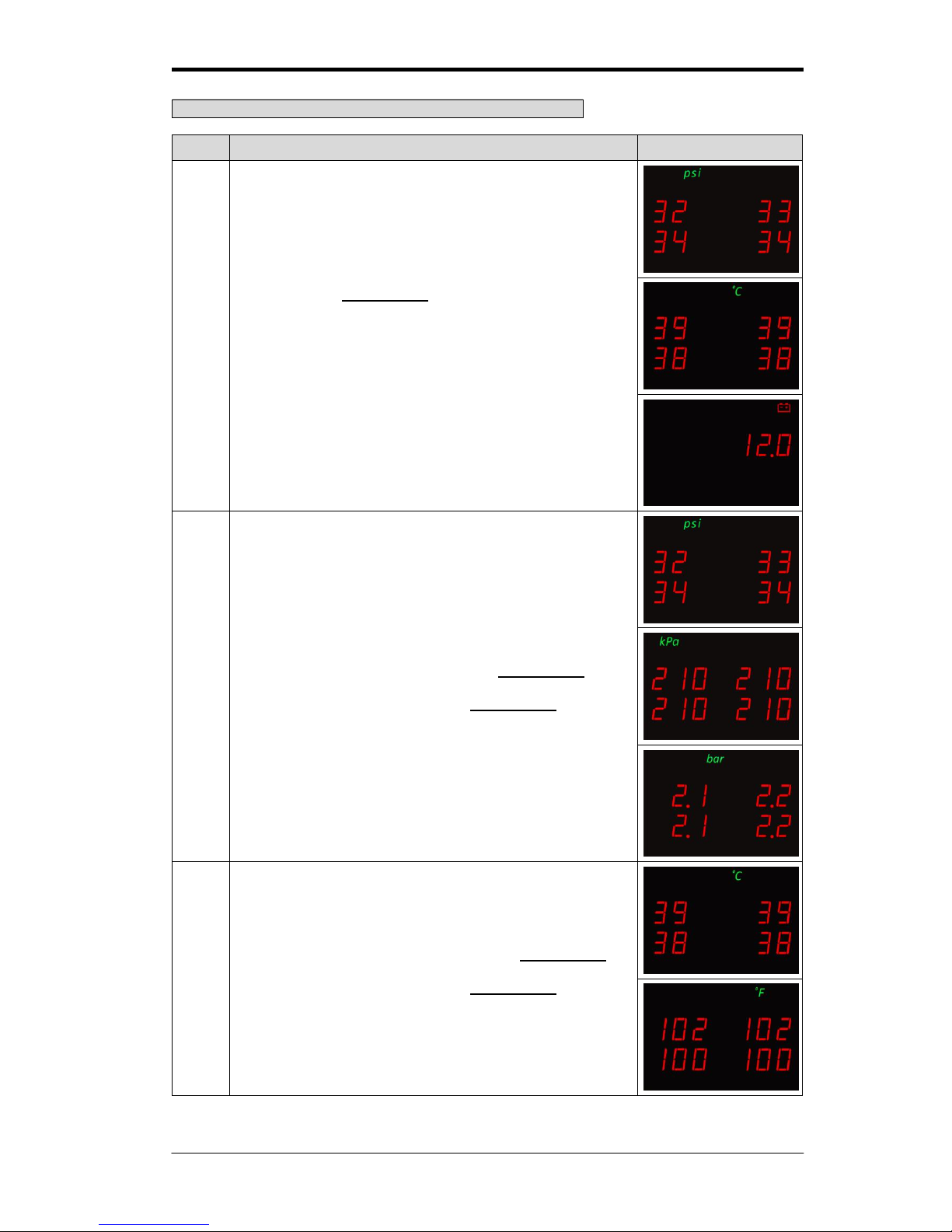
Choosing preferred Pressure Units and Temperature Units
Step
Operation process
Photograph
1
By pressing the function key, it will switch among
displaying the pressure unit, displaying the temperature unit,
displaying the battery voltage, and displaying both pressure
unit and temperature unit by turns. The operator can choose
which one to set up first.
2
If the pressure unit is chosen. Press the function key for 3
seconds, it will switch to kPa, psi, bar in turn. Once the
preferred unit is chosen release the function key.
3
If the temperature unit is chosen. Press the function key for
3 seconds, it will switch to oC and °F in turn. Once the
preferred unit is chosen release the function key.
Page 11
Manual for Tire Pressure Monitoring Systems, TPMS
11/22
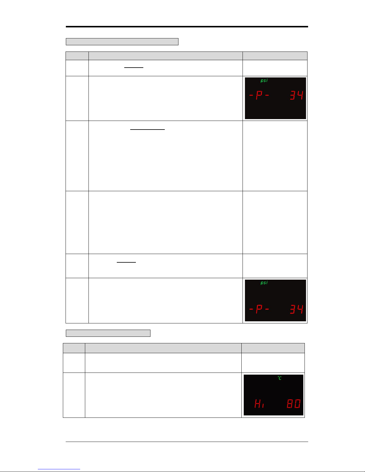
Standard Front/Rear Tire Pressure Setting
Tire Over Temperature Warning
Step
Operation process
Photograph
1
After the setting operation of standard tire pressure, the
systems will automatically entry the setting mode of high tire
temperature.
2
The display unit will show tire over temperature warning
setup value (the factory default value is 80oC / 176°F.
) for the tires.
Step
Operation process
Photograph
1
Pressing the set key for over 3 seconds can change to the
front tire standard pressure set up mode.
【Set】Key
2
The wireless receiver and display unit will show the preset
front tire standard pressure default (34 psi / 230 kPa / 2.3
bar).
3
By pressing the function key once, the psi value will add 1
unit; and the unit value will return to 20 psi when it has
reached 48 psi. ( the kPa value will add 10 units; and the
unit value will return to 140 kPa when it has reached
330kPa / the bar value will add 0.1 units; and the unit value
will return to 1.4bar when it has reached 3.3 bar) The
system will use this setting as the standard value for low
tire pressure monitoring, which means when the tire has
deflated to a pressure value lower than this setting, the
system will automatically start to warn the driver.
【Function】Key
4
As for the preset standard value 34psi/230kpa for tire
pressure monitoring. High tire pressure monitoring which
means when tire pressure has reached 51psi or 1.5 times
of the original standard value (the initial preset value is
345kPa or 3.5 bar).
For low tire pressure monitoring which means when tire
pressure has reached 27psi or 0.8 times of the original
standard value (the initial present value is 184 kPa or
1.8bar).
5
Press the set key to complete the front tire pressure
warning value setup mode. The system will automatically
enter the rear tire pressure set up mode.
【Set】Key
6
Set up rear tire standard pressure value by using the same
steps 1~5 from front tire pressure warning value set up
mode.
Page 12
Manual for Tire Pressure Monitoring Systems, TPMS
12/22
3
Press the function key to change the high temperature
figure.
The high temperature figure set up range is from 60oC to
100oC ( the °F value will add 1 unit; and the unit value will
return to 140 °F when it has reached 212 °F), the driver can
continually push the function key to adjust the appropriate
high temperature figure. When the tire temperature exceeds
this setting, the system will generate the warning signals.
【Function】Key
4
Press the set key to complete the high temperature setting
operation.
【Set】Key
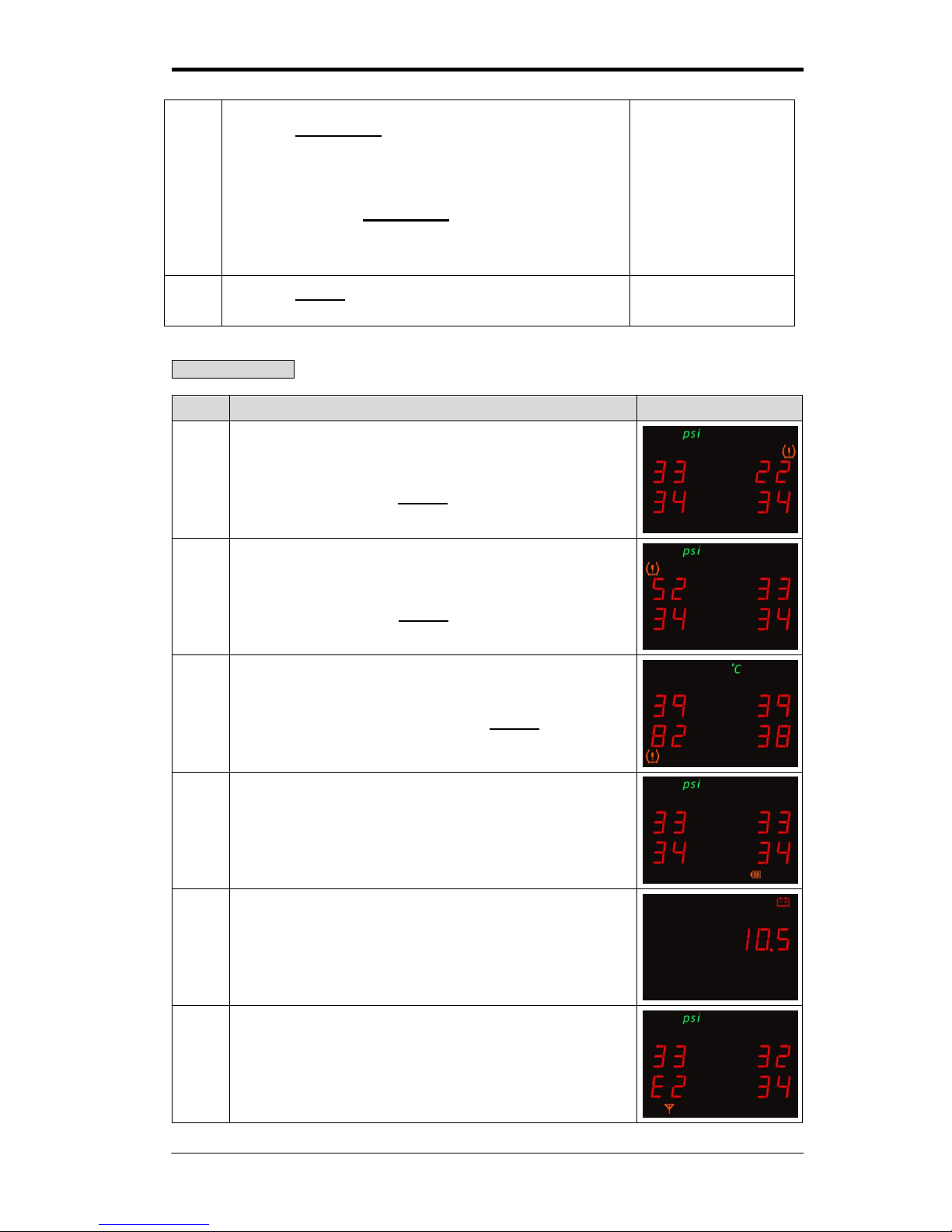
Alarm Instruction
Type
Warning Description
Photograph
1
The tire pressure of RF Tire (22 psi) is below tire pressure
default (27 psi), and it will active an alarm with “Beep sound”
to warn the driver, press set key to turn off the alarm.
2
The tire pressure of LF Tire (52 psi) is above tire pressure
default (51 psi), and it will active an alarm with “Beep sound”
to warn the driver, press set key to turn off the alarm.
3
The tire temperature of LR Tire (82 °C) is above tire
temperature default (80 oC), and it will active an alarm with
“Beep sound” to warn the driver, press set key to turn off
the alarm.
4
The battery voltage of Sensor is under battery voltage
default, which the battery check icon will illuminate.
5
When display is not in battery monitor mode, the battery
voltage icon will flash to warn the driver, when the battery
voltage of vehicle is below 11V.
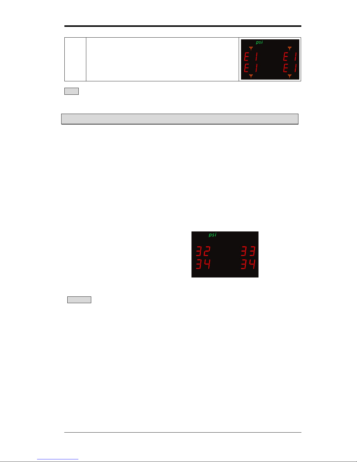
6
When it lasts 20 minutes above that wireless receiver
couldn’t receive one of the signal from wireless transmitter
sensor, the display will show E2; E1 indicates all wireless
transmitter sensor not receivable.
Page 13
Manual for Tire Pressure Monitoring Systems, TPMS
13/22
Note when display unite shows E1 or E2, place any wireless devices (cell phone, etc)
further away from display unit or locate a qualified tire service center to correct the
issue.
Reset for Tire Changes and Rotation
The rotation is necessary to prolong the life of your tires. The system can reset the tire
position to ensure the transmitter sensor can indicate the right position of your tires on display
unit. TPMS provides three modes of tire rotation methods and one mode for random
repositioning and single sensor replacement.
The product has adopted Orange Tire Orientation (OTO).
The system will automatically reset tire position on driving for a while after tire or sensor
change.
OTO can efficiently help end user save time for resetting.
Mode 1: Front to Rear tires exchanged
Mode 2: Tires diagonal exchanged
Mode 3: Front tires diagonal exchanged, and Rear tires parallel exchanged to Front.
Mode 4: Random tire repositioning
Mode 5: Single sensor replaced
No.4 No.1
No.3 No.2
Warming
1. Do not turn off the vehicles power during this process. Doing so will immediately
interrupt the repositioning setup process. The ignition can either be in the on or start
position (At this time, enter Mode 5 to use single sensor replaced).
2. After repositioning, check the display is detecting all tire pressures correctly. If the
system cannot work normally, please reset it and follow the instructions again.
No.1 → Front-right tire
No.2 → Rear-right tire
No.3 → Rear-left tire
No.4 → Front-left tire
Page 14
Manual for Tire Pressure Monitoring Systems, TPMS
14/22
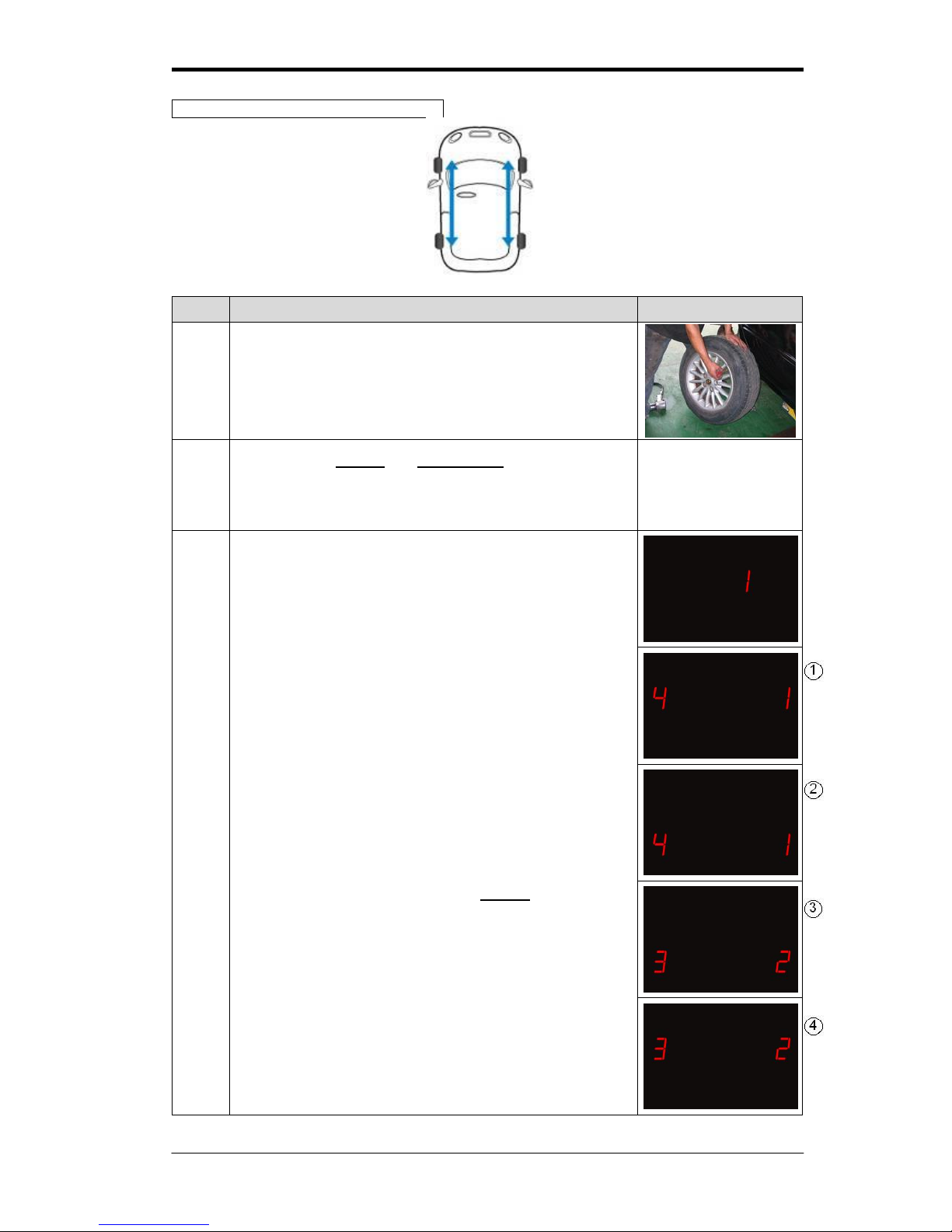
Mode 1: Front to Rear tires exchanged
Step
Operation process
Photograph
1
Rotate the tires. Front to Rear, and Rear to Front. To
prevent incorrect positioning, mark the tires.
2
Press both the set key and function key simultaneously for
5 seconds. The display will flash red, and a “beep” sound
will be heard. You can release the buttons, and the system
will have entered into mode 1.
【Function】Key
【Set】Key
3
3-1
After entering mode 1, the display will show “1”.
3-2
Numbers show in LED lights stands for tires’ ID, photograph
○
1 and ○3 means tires position before changing,
photograph ○2 and ○4 means after changing.
3-3
The operator only needs to press the set key for 3 second
and listen for the “beep”. This means that mode 1 has been
chosen and will exchange all four sensors ID positions and
will automatically return the monitoring status to normal.
Page 15
Manual for Tire Pressure Monitoring Systems, TPMS
15/22
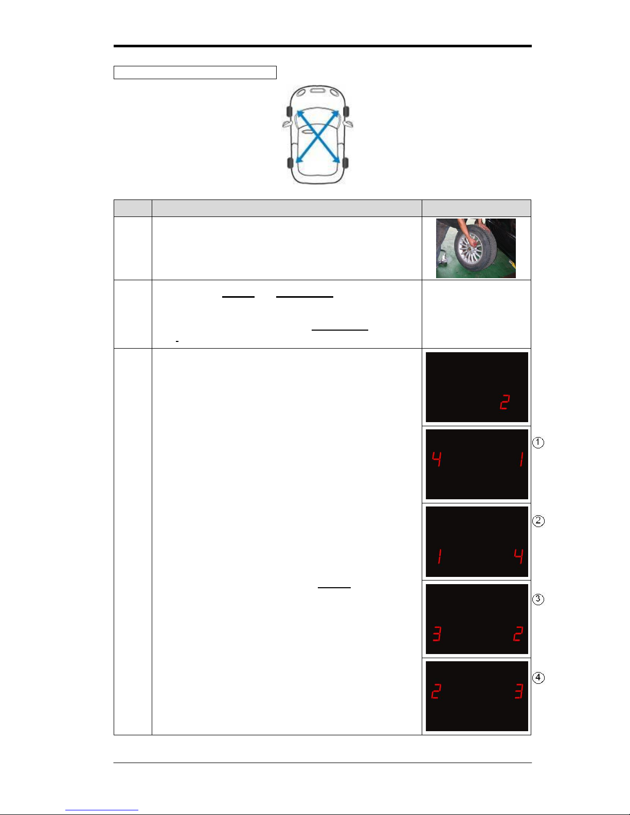
Mode 2:Tires diagonal exchanged
Step
Operation process
Photograph
1
Rotate the tires diagonally. To prevent from incorrect
positioning, mark the tires.
2
Press both the set key and function key simultaneously for
5 seconds. The display will flash red, and a “beep” sound
will be heard. You can release the buttons, and the system
has entered into mode 1. If presses function key again,
then the system has entered into mode 2.
【Function】Key
【Set】Key
3
3-1
After entering mode 2, the display will show “2”.
3-2
Numbers show in LED lights stands for tires’ ID, photograph
○
1 and ○3 means tires position before changing,
photograph ○2 and ○4 means after changing.
3-3
The operator only needs to press the set key for 3 second
and listen for the “beep”. This means the mode 2 has been
chosen and will exchange all four sensors ID positions and
will automatically return the monitoring status to normal.
Page 16
Manual for Tire Pressure Monitoring Systems, TPMS
16/22
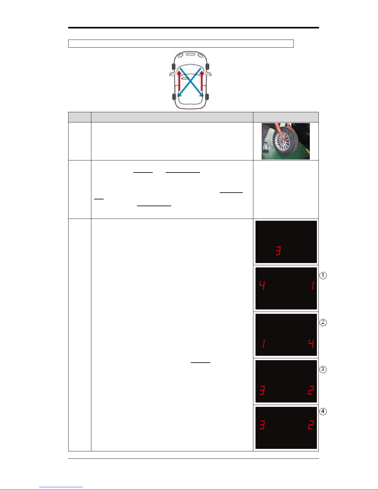
Mode 3:Front tires diagonal exchanged, and Rear tires parallel changed to Front
Step
Operation process
Photograph
1
Rotate the front tires diagonally to the rear, and the rear tires
parallel to the front. To prevent incorrect positioning, mark
the tires.
2
Press both the set key and function key simultaneously for
5 seconds. The display will flash red light, and a “beep”
sound will be heard. You can release the buttons, and the
system will have entered into mode 1. Re-press function
key for 1 second and wait for “beep” then the LED will show
“2”, re-press the function key you will then see “3”, the
system will have entered into mode 3.
【Function】Key
【Set】Key
3
3-1
After entering mode 3, the display will show “3”
3-2
Numbers show in LED lights stands for tires’ ID, photograph
○
1 and ○3 means tires position before changing,
photograph ○2 and ○4 means after changing.
3-3
The operator only needs to press the set key for 3 second
and listen for the “beep”. This means that mode 3 has been
chosen and will exchange all four sensors ID positions and
will automatically return the monitoring status to normal.
Page 17
Manual for Tire Pressure Monitoring Systems, TPMS
17/22
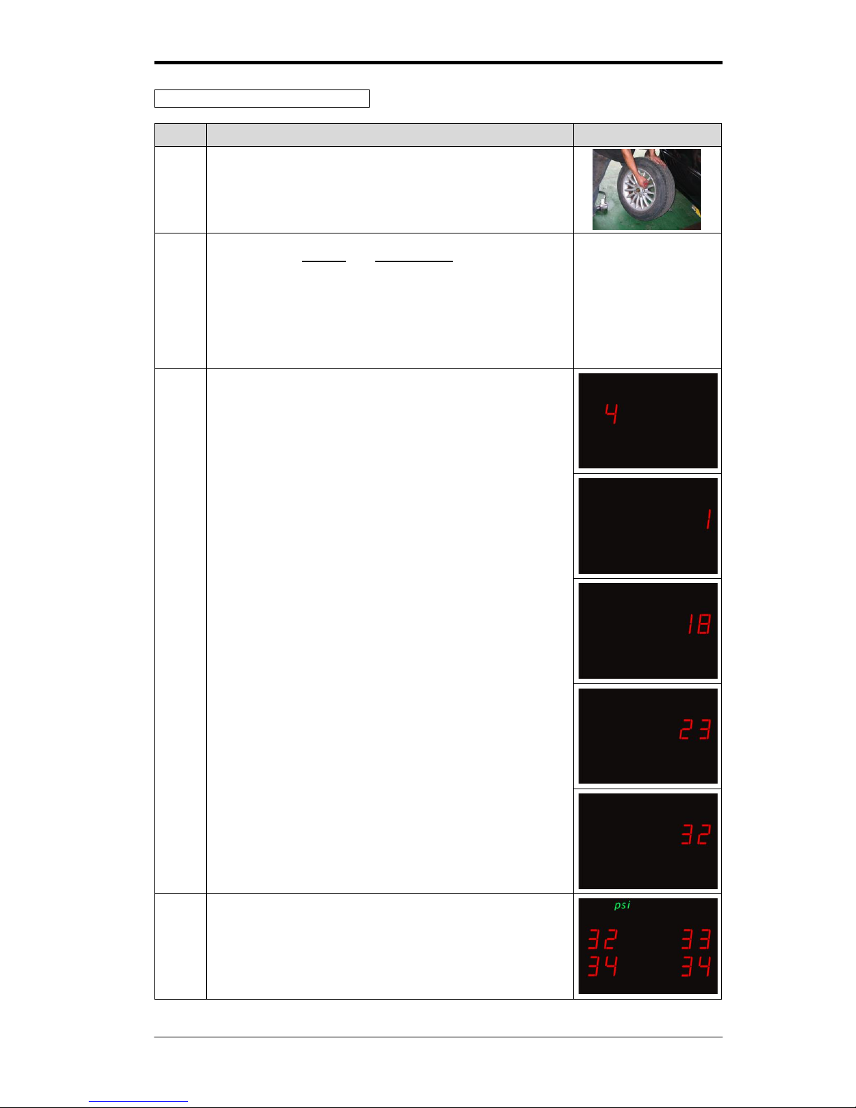
Mode 4:Random re-position tires
Step
Operation process
Photograph
1
The tire shop will check the tire for abrasion and rotate tires
into the appropriate position.
2
Press both the set key and function key simultaneously for
5 seconds. The display will flash red, and a “beep” sound
will be heard. You can release the buttons the system will
have entered into mode 1. Continue to press the function
key, each time for one second and each time wait for the
beep until the display shows”4”., After entering into mode 4
the LED will show “4”.
【Function】Key
【Set】Key
3
3-1
It will take about two second after entering mode 4, and the
display will show “4”.
3-2
When Tire No.1 needs to be reconfigured, deflate Tire No.1
once below 27 psi (tire low pressure default), and wait for
the receiver to receive the signal. When tire No. 1 receives
the signal, you will hear alarm “beep”. Then, start inflate the
tire No.1, it will keep on “beep” till Tire No. 1 is completely
inflated to normal pressure.
3-3
After finishing all the steps above. In the mode 4, the
numbers will show “1” and turn to “2” automatically.
4
Repeat the 3-2 step above for tire No.2, No.3 and No.4
System will be back to monitoring condition automatically, and
receiver start to receive signals of tire pressure & tire
temperature.
Page 18
Manual for Tire Pressure Monitoring Systems, TPMS
18/22
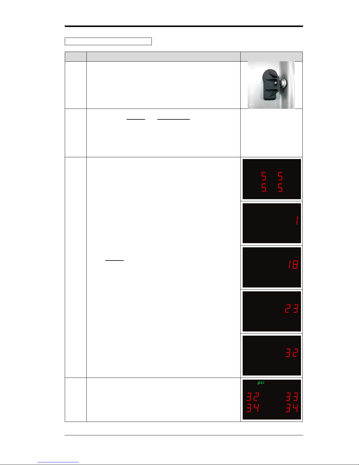
Mode 5: Single sensor replaced
Step
Operation process
Photograph
1
Take off the broken sensor and replace it with a new sensor.
( if you are only checking for a signal problem from Mode 4
instructions, there is no need to take off the sensor)
2
Press both the set key and function key simultaneously for
5 seconds. The display will flash red, and a “beep” sound
will be heard. You can release the buttons, and the system
will have entered into mode 1. Continue to repress the
function key for four times, and then the system will switch
into mode 5.。
【Function】Key
【Set】Key
3
3-1
It will take about 2 seconds after entering mode 5, the
display will show “5”
3-2
Press set key to choose tire which new sensor installed,
LED will show Tire No.1 / 2 / 3 / 4.
3-3
When Tire No.1 (RF Tire) needs to be replaced, deflate tire
No.1 below 27 psi (tire low pressure default value) and wait
for the receiver to receive the signal. When Tire No. 1
receives the signal, you will hear “beep”. Then, start inflate
tire No.1, it will keep on “beep” till Tire No. 1 is completely
inflated to normal pressure.
4
After completing all the steps above, System will be back to
monitoring condition automatically.
Page 19
Manual for Tire Pressure Monitoring Systems, TPMS
19/22
Appendix
Glossary
kPa
Pressure reading in Kilo Pascal
psi
Pressure reading in pound per square inch
bar
Pressure reading in bar
°C
Temperature reading in degrees Celsius
°F
Temperature reading in degrees Fahrenheit
Inflating Pressure
environment
Recommended inflation pressure of a tire at ambient temperature
of 25˚C / 77 °F by vehicle manufacturers.
Low Pressure Alert
Visual and audible warning, this is activated when the tire’s
pressure goes below the preset level. Initial low pressure alert is
27 psi
High Pressure Alert
Visual and audible warning, this is activated when the tire’s
pressure goes higher than the preset level. Initial High pressure
alert is 51 psi
High Temperature Alert
Visual and audible warning, this is activated when the tire’s
temperature goes higher than the preset level. Initial High
temperature alert is 80°C.
Display / Receiver
Module
The electronic module mounted inside the vehicle that alerts the
driver of any tire irregularities.
Sensor / Transmitter
Module
The electronic module mounted on the wheels that measure the
air pressure and temperature of the tire.
Annexes
Annex 1
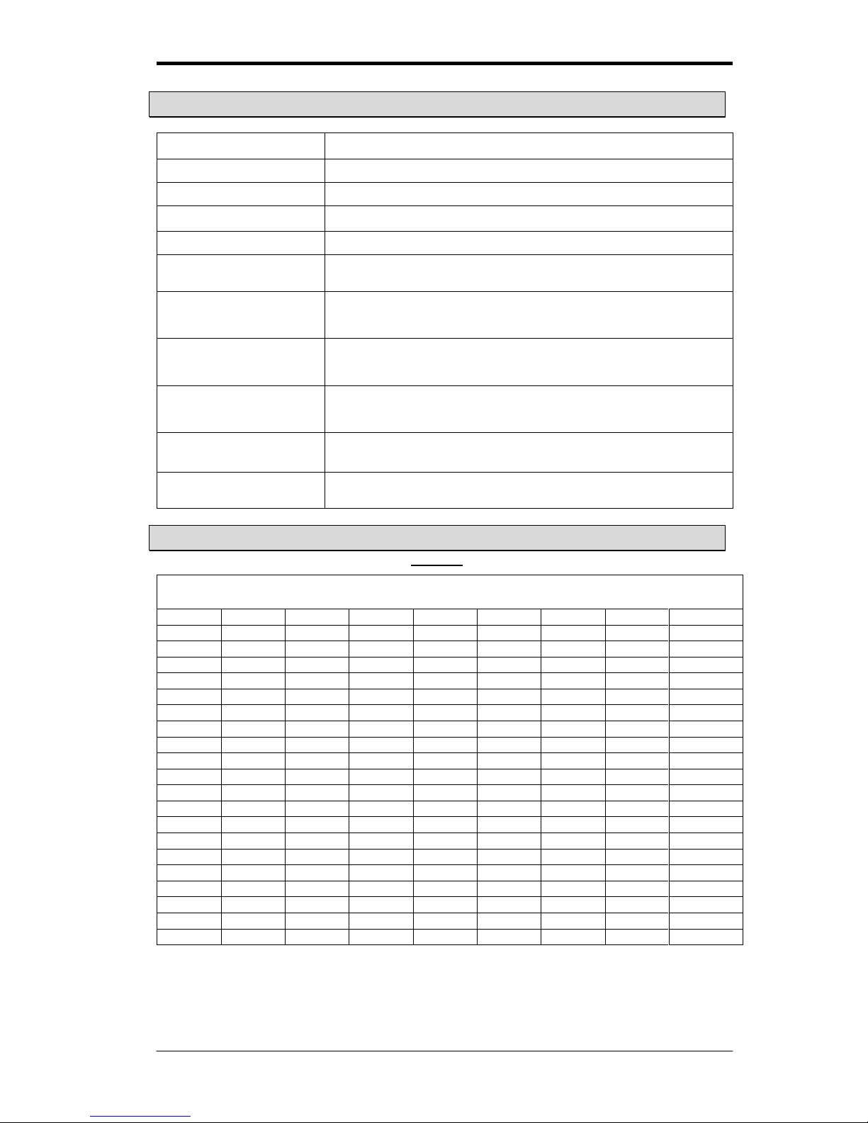
kPa , psi, bar Conversion Table
kPa
psi
bar
kPa
psi
bar
kPa
psi
bar
10 1 0.1
210
30
2.1
410
59
4.1
20 3 0.2
220
32
2.2
420
61
4.2
30 4 0.3
230
33
2.3
430
62
4.3
40 6 0.4
240
35
2.4
440
64
4.4
50 7 0.5
250
36
2.5
450
65
4.5
60 9 0.6
260
38
2.6
460
67
4.6
70
10
0.7
270
39
2.7
470
68
4.7
80
12
0.8
280
41
2.8
480
70
4.8
90
13
0.9
290
42
2.9
490
71
4.9
100
15 1 300
44
3.0
500
73 5 110
16
1.1
310
45
3.1
510
74
5.1
120
17
1.2
320
46
3.2
520
75
5.2
130
19
1.3
330
48
3.3
530
77
5.3
140
20
1.4
340
49
3.4
540
78
5.4
150
22
1.5
350
51
3.5
550
80
5.5
160
23
1.6
360
52
3.6
560
81
5.6
170
25
1.7
370
54
3.7
570
83
5.7
180
26
1.8
380
55
3.8
580
84
5.8
190
28
1.9
390
57
3.9
590
86
5.9
200
29 2 400
58
4.0
600
87
6
Page 20
Manual for Tire Pressure Monitoring Systems, TPMS
20/22
Annex 2
Warranty Policy
We warrant our products for one year (365 days) from the date of original purchase to be free
from defects in materials and workmanship. If, during this period, the product fails under
normal usage, because of a manufacturing defect, we will replace or repair the item. To obtain
repair or replacement under the terms of this warranty, please return the product to the place
of purchase. Proof of purchase and date of purchase are required to validate the warranty
claim.
All implied warranties, including the warranty of merchantability, are limited to this same ninetyday period from date of original purchase. We are not liable for any direct or consequential loss
or property damage arising from any use of this product. This warranty gives you specific legal
rights, and you may also have other rights, which vary from state to state.
This does not affect your statutory rights.
Note: Warranty including “Wireless Display Unit and Wireless Transmitter Sensor and Power
Connection cable”, not including other accessories.
When remove transmitter sensors to different tires and replace new transmitter sensors,
suggest changing all the valve steams and screws.
Warning
1. Only use TPMS sensor replacement parts (these can be purchased from Agents).
TPMS cannot use other brands of TPMS sensors for replacement parts. Using other
brands will be cause failure and will void the warranty.
2. The power connection is NOT COMPATABLE with USB interface; please do not plug
in any USB devices.
Any questions pertaining to warranty information or other questions not answered in the
preceding pages can be answered by the place of purchase or by Orange Electronic service email address:
For updated TPMS information and Orange products visit the Orange Electronic website:
www.orange-electronic.com
Thank you for your purchase and enjoy your TPMS!
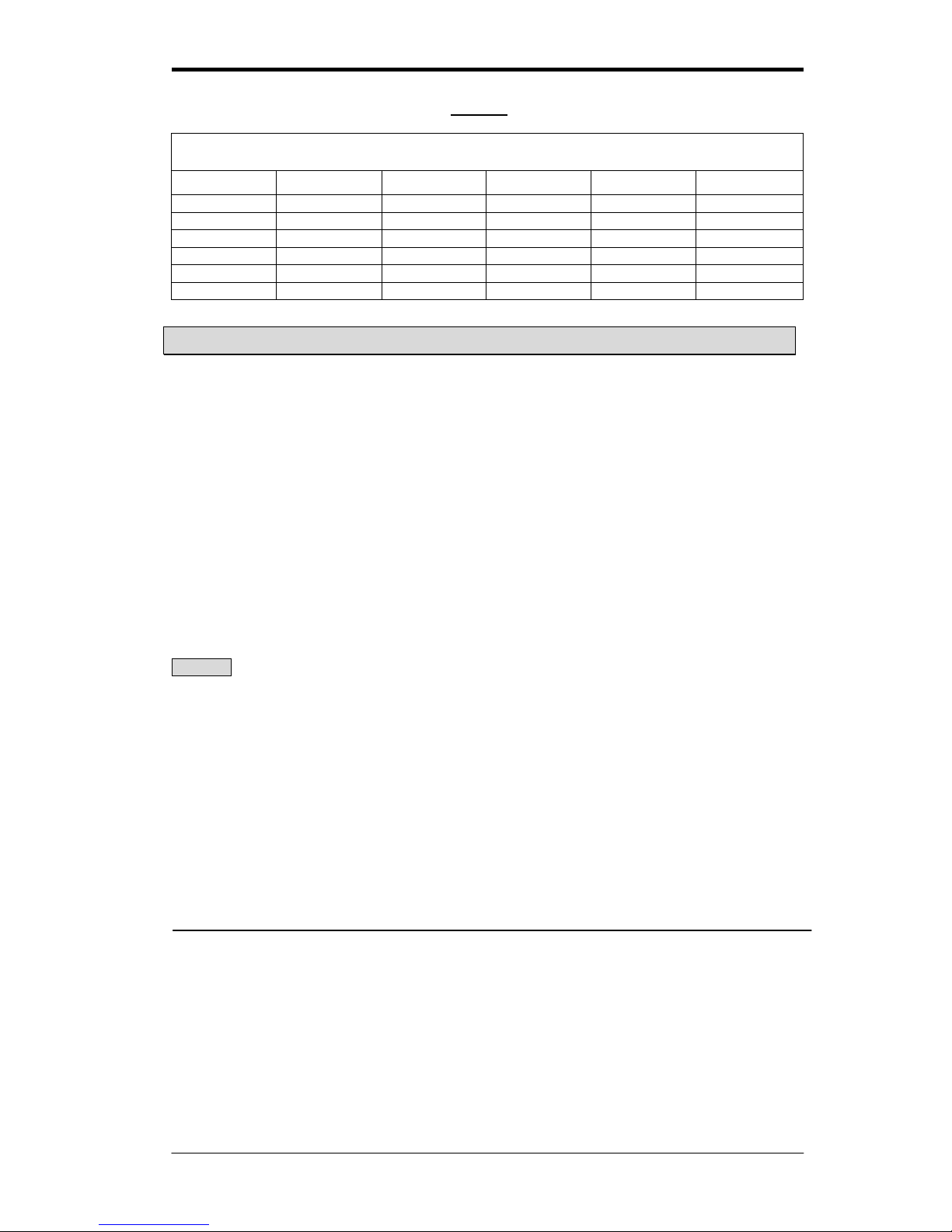
°C To °F and °F To °C Conversion Table
°C
°F
°C
°F
°C
°F
-40
-40
20
68
80
176
-30
-22
30
86
90
194
-20
-4
40
104
100
212
-10
14
50
122
110
230 0 32
60
140
120
248
10
50
70
158
125
257
Page 21

Manual for Tire Pressure Monitoring Systems, TPMS
21/22
Troubleshooting Guide
1. The receiver shows no sign or any information after its power is turned on.
1.The power cord connector is not fully contacted with the receiver
Solution: Remove the power cord and plug it into the outlet again until it is
contacted completely.
2.The power cord failed
Solution:Ask your distributor to have your power cord replaced and send the
defected one back to manufacturer for repair.
3. The battery is run out of power.
Solution:If the battery voltage is always lower than 9V every time you start the
engine, it is recommended that the car should be brought to the service center for
inspection.
4. The digits shown on the display panel become incomplete, or the light indicators
become abnormal.
Solution:Send the defected receiver display back to agent for repair and
reconfigure its ID using the Tire Switching Mode (Mode IV).
5. The fuse is blown in display
Solution:Send the defected receiver display back to agent for repair and
reconfigure its ID using the Tire Switching Mode (Mode IV).
2. The Set button or the Conversion button has no response.
1. The inner circuits of the receiver failed
Solution:Ask your distributor to have your receiver replaced, reconfigure its ID
using the Tire Switching Mode (Mode IV), and send the defected receiver back to
manufacturer for repair.
3. The receiver cannot receive signal from one or some certain tires (but not all of
them) after its power is turned on the numeric values representing the
locations of those tires displayed on the screen become “E2”.
1. There is interference from other electronic device in the vehicle.
Solution:Remove other electronic device in the vehicle to determine if TPMS is
interfered by those removed devices.
2. The IDs of those tires do not set up correctly
Solution: Ask your installation supplier to reconfigure the IDs of those tires by
using the Single Sensor Replacement Mode(Mode V)
3. The transmitter of those tires failed.
Solution:Ask your distributor to have those transmitters replaced, reconfigure the
IDs of those tires by using the Single Sensor Replacement Mode (Mode V), and
then send the defected transmitter back to manufacturer for repair.
Page 22

Manual for Tire Pressure Monitoring Systems, TPMS
22/22
4. The receiver cannot receive signal from any of the four tires after its power is
turned on the numeric values representing tire locations displayed on the
screen all become “E1”.
1. There is interference from other electronic device in the vehicle.
Solution:Remove other electronic device in the vehicle to determine if TPMS is
interfered by those removed devices.
2. The inner circuits of the display panel failed.
Solution:Ask your distributor to have your receiver replaced, reconfigure its ID
using the Tire Switching Mode (Mode IV), and send the defected receiver back to
manufacturer for repair.
5. The buzzer has no sound output.
1. The inner circuits of the receiver failed.
Solution:Ask your distributor to have your receiver replaced, reconfigure the IDs
of the tires using the Tire Switching Mode(Mode IV),and then send the defected
receiver back to manufacturer for repair
6. The pressure (or temperature)values show the wrong tire locations
1. The IDs of the four tires are not configures correctly
Solution: Ask your installation supplier to reconfigure the IDs of the tires by using
the Tire Switching Mode (Mode IV or Mode V).
2. After rotating the tires, it cannot reconfigure the IDs from sensors.
Solution: Ask your installation supplier to reconfigure the IDs of the tires by using
the Tire Switching Mode (Mode IV or Mode V).
Thank you for your purchase and enjoy your TPMS!
Manufacturer:
Orange Electronic Co., LTD
www.orange-electronic.com
5F, No.29, Keya Rd, Central Taiwan Science Park, Taichung 42881, Taiwan
Phone: +886-4-2560-2766
Email: [email protected]
 Loading...