

Page 1

Page 2

Ever since the founding of the company in 1968,
Orange has been a pioneering force in the guitar
amplification industry. Today, with a team of the
world’s finest engineers, Orange continues to
push back the boundaries of product design.
THANK YOU FOR CHOOSING ORANGE
Our commitment to craftsmanship and quality
control has allowed our products to stand the
test of time, giving their owners as much
pleasure now as the day they were bought. To
maintain this level of excellence, all Orange
products are put through many rigorous test
procedures before leaving the factory.
2
Page 3
WHAT’S IN THE BOX
1 x Valve Tester MKII
1 x Power Supply
1 x Mains lead
1 x Manual
1 x Pencil
3
Page 4
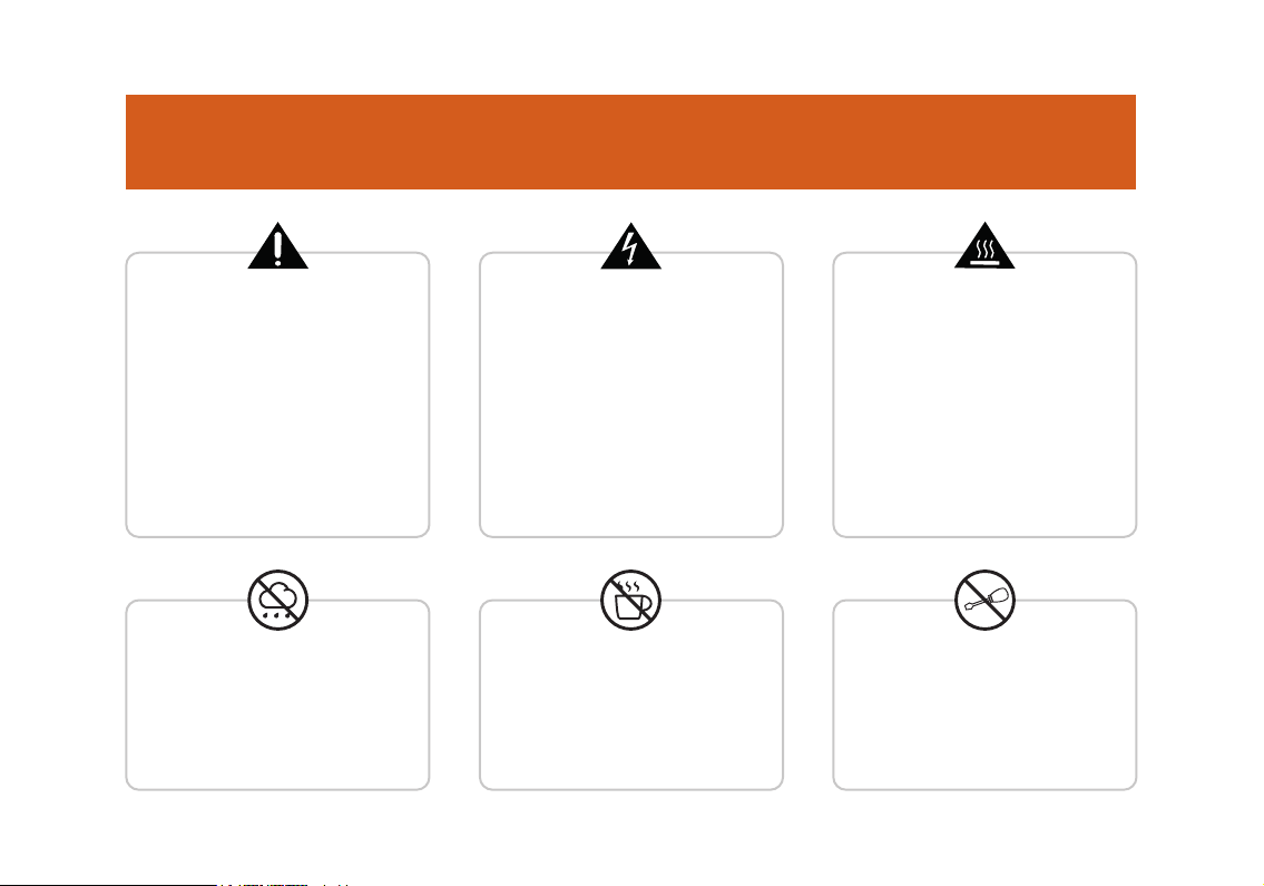
IMPORTANT SAFETY
The exclamation point within an
equilateral triangle and "WARNING" are
intended to alert the user to the
presence of important operating or
servicing instructions. Failure to heed
the instructions can result in severe
injury or death.
This equipment should be used under
the supervision of an adult at all times.
To reduce the risk of fire and electric
shock do not expose this apparatus to
rain or moisture. Do not use in damp
environments, e.g. bathrooms etc.
The lightning flash with arrowhead
symbol, within an equilateral triangle,
is intended to alert the user to the
presence of un-insulated ‘dangerous
voltage’ within the product’s
enclosure that may be of sufficient
magnitude to constitute a risk of
electric shock to persons.
Do not place objects containing
liquids on, or near the product.
Do not operate this apparatus or
connect/disconnect a power plug
whilst hands are wet.
The “Caution, hot surface” symbol
indicates the marked item may be hot.
Ensure the apparatus is installed with
plenty of space around the unit
(> 6”/12.5cm) as this apparatus may
generate heat under normal use. This
equipment is not intended to be used on
soft support (like beddings, blankets etc.).
This equipment should always be placed
on a flat, stable surface.
Do not attempt to gain access to
the interior of the product. No user
serviceable parts inside. Refer all
servicing to qualified servicing
personnel.
4
Page 5

The Orange Valve Tester MKII (VT MKII) supply input is
19V DC 65W. The DC input socket is centre positive
polarity and the barrel plug is a ‘standard 2.5mm type.’
To avoid the risk of product damage it is highly recommended to only use the power supply supplied with the
product, or an exact equivalent.
This device complies with the Canadian Interference Regulations CAN ICES-3(B)/NMB-3(B).
This device complies with Part 15 of the FCC rules. Operation is subject to the following two conditions:
Warning valves can get hot during testing, ensure they
are cool to handle before removing from the valve tester.
Valves are fragile, so always be gentle when handling
them and attaching or detaching them from the VT MKII.
!
2) This device must accept any interference received, that may cause undesired operation.
1) This device may not cause harmful interference.
Note: This equipment has been tested and found to comply with the limits for Class B digital device, pursuant to Part 15 of the FCC Rules. These limits
are designed to provide reasonable protection against harmful interference in a residential installation. This equipment generates, uses and can radiate
radio frequency energy and if not installed and used in accordance with the instructions, may cause harmful interference to radio communications.
5
Page 6

WHY CHOOSE THE ORANGE VT MKII?
Commercial valve testers have been available, almost since valves were invented, incorporating many excellent
techniques and designs over the years. However, the vast majority have a number of common features, which we
considered to be a barrier to the modern valve user namely:
• They require a certain level of user interaction in that parameters have to be set for individual valves being tested.
• They require a certain depth of knowledge about valve theory, which some users may not have.
• The results obtained on meters or digital readouts require a certain level of user interpretation.
• They are often quite large and bulky.
In a lot of cases, they are also not very portable and
since most are mains operated, require selection of
mains voltage if required to be used in other than their
native country. When developing the VT MKII we
decided to ‘break the mould’ to produce a fully
automatic valve tester, which performs a wide range of
tests quickly and accurately.
Requiring little or no knowledge of valve theory, it can
be operated by experienced users and those who just
want to know that the valves in their amplifier are in
good condition. It requires no user interaction other
than inserting the valve to be tested into the correct
socket, selecting the type from a list using two
up/down buttons using an LED bar display, then finally
pressing an ‘OK’ button to start the test.
6
Page 7

The test then proceeds without any further user input
and elapsed time is shown on the LED display during the
test, then one of three LED’s is lit to indicate a ‘GOOD’,
‘WORN’ or ‘FAIL’ condition.
In addition, the LED display indicates a ‘matching
number’ which is based on a summation of the many
results obtained during the test and has been specifically
designed to reflect the operation of the valve, according
to its normal function in an audio amplifier.
For example, power valves are graded with their
emission and control grid performance as primary
factors, whereas pre-amp valves are graded with
different parameters to reflect their role in signal
amplification and phase splitting applications. If the
valve is faulty or worn, then this will be indicated at the
end of the test.
The simplicity of operation belies what is going on
‘inside the box’, where a sophisticated microprocessor
controlled testing system (incorporating TubeSyncⓇ
Technology) is in operation, allowing full control over all
inter-electrode switching and measurement operations.
In addition all voltages required by the tester are
internally derived, stabilised and controlled by the
microcontroller, allowing rapid static and transient
tests without generating unnecessary heat. The test
algorithms used have been developed using data from
tests on hundreds of new, used and faulty valves.
We are passionate about valve technology and our aim
throughout has been to make the Orange VT MKII a
sophisticated, modern, truly portable valve tester
which is primarily useful but also stylish, appealing to
all valve users whether amateur, professional or in the
music retail trade.
7
Page 8

BEFORE USING YOUR VALVE TESTER
With the VT MKII, Orange has designed a compact, safe and simple alternative to the large, dubious and
complicated valve testers of the past. However, despite its small size the VT MKII is a highly accurate and sensitive
piece of test equipment, and should be treated as such.
When in use the VT MKII is taking thousands of micro measurements and performing a vast array of tests in order
to grade your valves. These tests measure very small voltage and current changes under high impedance
conditions, which means a number of external factors can affect the end results.
TO OBTAIN THE MOST CONSISTENT READINGS, WE ADVISE OBSERVING THE FOLLOWING:
With temperature being a factor we suggest that the
VT MKII is used, wherever practically possible, in a
location where temperature and humidity will remain
constant. If inconsistent test results are being
observed during the first couple of tests allow for
further time for the effects of humidity, condensation
and temperature to neutralise and re-test.
The grading/matching system is based on a decision
made after performing over 20 tests. For this reason
and the sensitive nature of valves (particularly 12AX7/
ECC83s) some slight variance may be seen during
testing. If this is observed allow the valve to cool, move
the VT MKII into an area of constant conditions and
re-test.
8
Page 9

Any condensation which may occur on the valve bases
or internally can influence initial results. Due to the
thermal insulation properties of the packaging and the
high thermal mass of the metal case, the VT MKII may
remain at a very low temperature for a considerable
time if left in the packaging. If it is brought into a warm
room and immediately used, condensation will
naturally occur and produce false test readings. We
recommend the VT MKII is allowed to stand for around
30 minutes out of its packaging before initial use for
these effects to subside.
! !
%
Do not test hot or warm valves. The VT MKII uses high
voltages to ensure accurate readings from the valves
which are tested with the correct voltages as stated in
their manuals. Under testing, the valve will become
warm and this heat will alter impedances inside the
valve. If the same valve is then repeatedly tested
before being allowed to return to room temperature, or
if a warm valve is tested having just been used (e.g. in
an amplifier), false readings will be given. We advise
leaving valves to reach or return to room temperature
before testing.
9
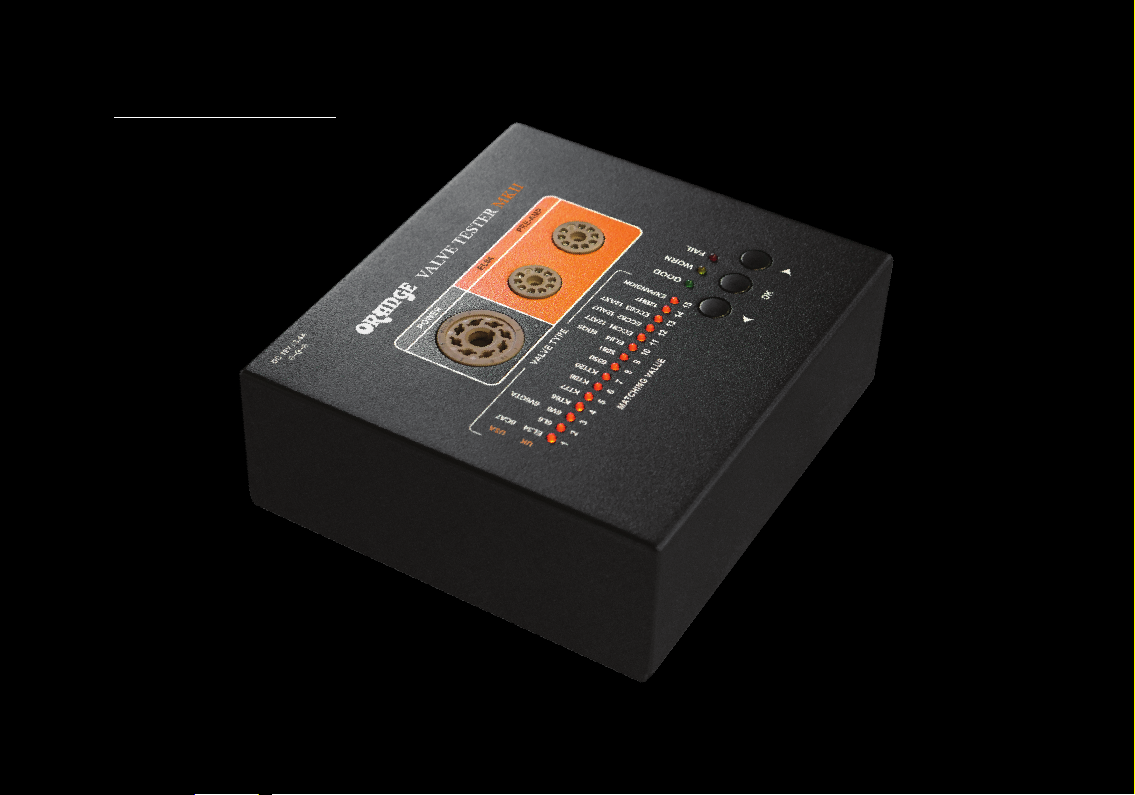
Page 10

CONTROLS AND FUNCTIONS
A B C
Valve socket for octal power valves.
A
Valve socket for EL84 valves.
B
Valve socket for pre-amp valves.
C
Selected valve type text (both UK and US).
D
Valve matching value (range between 1 & 15).
D
E
F
G
E
Valve status result: GOOD, WORN, FAIL.
F
Control buttons. Centre button selects valve
G
type and starts the test. The two outer buttons
move valve selection from right to left.
10
Page 11

VALVE SOCKETS & VALVE SELECTION
VALVE SOCKETS PHYSICALLY DAMAGED VALVES
No damage will occur to the VT MKII by testing faulty or
EL34/6CA7; 6L6;
6V6/6V6GTA; KT66;
KT77; KT88; KT120
6550; 5881;
EXPANSION MODULE
EL84/6BQ5
ECC81/12AT7;
ECC82/12AU7;
ECC83/12AX7; 12BH7
damaged valves.
Under no circumstances should any attempt be made
to insert into the test socket or to test a valve which is
physically damaged, as this could present a hazard to
the user or others.
If a glass valve envelope is accidentally damaged during
a test, the ‘OK’ button should be used to terminate the
test and the power connector removed.
The valve should then be allowed to cool after which it
should be removed using protective gloves and then
safely disposed of. DO NOT touch any exposed metal
parts of the valve during the operation and ensure that
no fragments of glass remain around the tester before
using it again.
!
11
Page 12

USING YOUR VALVE TESTER
STEP 1 STEP 2
Decide which valve you would like to test and identify
what valve test socket is required for the test.
Octal power valves (EL34s, KT66 etc.) use valve socket 1.
EL84 valves use valve socket 2.
Preamp (ECC83, 12BH7) valves use valve socket 3.
STEP 3 STEP 4
Ensure the supplied power lead is connected to the
tester and is switched on. Press the ‘OK’ button to start,
then by moving the left and right selector buttons
select the valve type which you are about to test.
When the correct valve type has been selected press
‘OK’ again and the test will commence.
Carefully insert the valve into the correct valve socket and
ensure it is seated correctly.
Only one valve must be inserted into the tester at a time.
Valves must be tested at room temperature.
Testing a hot valve may result in a failure as the tester is
calibrated to heat the valve up as part of the test sequence.
It takes approximately two minutes for the tester to test
a valve, during this time a number of orange LEDs will
illuminate and flash.
As the test progresses the number of LEDs illuminated
will gradually decrease until the test is completed. If the
valve fails at any point, the test is automatically
terminated and the red ‘FAIL’ LED is illuminated.
12
Page 13

STEP 5 TEST STATUS
Once the test completes and the green, yellow or red
indicator lights, then the test is finished; however, as
valves may get hot during the test, we recommend that
you make sure that the glass envelope is cool before
attempting to remove it.
In any case, we recommend the use of protective gloves
when handling valves.
Note: Some specific faults found by the VT MKII may be either transitory or not immediately obvious when used in normal
operation. However, they could manifest themselves when the valve comes under stress or heavy load during a performance.
GREEN - If the green LED is illuminated this indicates
that the valve is GOOD.
YELLOW - If the yellow LED is illuminated this indicates
that the valve is worn and should be replaced
as soon as possible.
RED - If a red LED is illuminated this indicates that the
valve has failed.
In the case of a RED FAIL light the tester will also display
a number ranging from 1-8, this reflects the valve failure
mode. (See the fault log at the back of the handbook).
For example : if the FAIL LED and LED 7 are illuminated
simultaneously after a test, the valve is a fail and the
reason for the failure is due to control grid leakage.
13
Page 14

NEW FEATURES ON THE VT MKII
A more rugged mechanical design
with improved test sockets
Improved algorithm with higher
current capability
Valve failure mode identification
Capability to function with external
expansion modules enabling the testing of
other valve types such as rectifiers and EF86s
New enhanced grid leakage
detection test
New microphony function for ECC81, ECC82
and ECC83 and 12BH7 pre-amp valves
New thermal runaway test
Capability to test directly heated valves
such as a 300B via the expansion module
14
Page 15

VALVE MATCHING NUMBER
A ‘matching number’ indicated by the LED(s) at the end
of the test, is based on a combination of measured
parameters to give an indication of how the valve will
perform, according to its typical function in an amplifier.
After the valve has been tested, the tester will assign a
matching number ranging from 1 to 15. Basically: the higher
the value, the higher the gain of the valve. If a number of
valves are tested, the gain or ‘matching valve’ can then be
used to group together pairs or quads of valves.
VALVE MATCHING VALUE FOR DOUBLE TRIODE
(PRE-AMP VALVES)
Double triode (pre-amp valves) have two valves inside one
envelope i.e. an A & B side. After the MK II has tested a
double triode (providing that the valve passes) two
matching value LEDs will illuminate.
For section A the LED will flash and for section B the LED
will be constant. If only one constant LED is illuminated,
this means that both sides of the valve are the same.
In general, the closer the LEDs are together the better,
if two matching valves are apart by more than 6 values
the VT MKII will fail the valve. See the examples below.
Both sections of the valve are fairly well matched.
Both sections of the valve are the same (one constant LED).
15
Page 16

MICROPHONY MODE
To begin the microphony test insert the valve into
the PRE-AMP socket. (ECC81, ECC82, ECC83, 12BH7
valves only).
Toggle along to number 15 and hold the right
button down for 3 seconds. When the yellow light
comes on the valve is heating up.
When the valve is heated, the yellow light will go out and
the green will come on. The valve is now ready, tap the
valve gently with a pencil to test microphony. Note: If
there is any noise present in the valve some LEDs will
illuminate prior to tapping.
The higher the LEDs go in the moving LED bar, the
greater the microphonic disturbance. Note: this test is
indicative only, however with experience the user can
easily detect a valve that exhibits a microphony issue.
16
Page 17

EXPANSION MODULES
Insert the expansion module, then select number 15
using the right arrow button. The yellow and green light
will illuminate for a second and then go out. This
indicates the tester has downloaded the test parameters
for the particular valve.
The number 15 LED should then remain solid, LEDs 1-14
will flash. to start the test press the OK button.
Expansion modules are available to purchase separately.
For further information please see orangeamps.com
17
Page 18

FAULT LOG
FAULT NUMBER
1 - Immediate fail
1 - Fail during test
2
3 - Pentode test
3 - Triode test
4 - Pentode test
4 - Triode test
5 - Pentode test
5 - Triode test
6 - Pentode test
6 - Triode test
7
8
REASON FOR FAULT
Heater open circuit or value missing
Heater current below minimum valve for valve type
Heater current too high
Anode current exceeds max valve for valve type
Anode 1 current exceeds max valve for valve type
Anode current does not achieve min value for valve type
Anode 1 current does not achieve min value for valve type
Screen grid current exceeds max value for valve type
Anode 2 current exceeds max valve for valve type
Screen current does not achieve min value for valve type
Anode 2 current does not achieve min value for valve type
Control grid leakage
Thermal runaway during test
ALTERNATIVE REASON
Total or partial short circuit
Internal leakage or short
Internal leakage or short
Very low emission
Very low emission
Internal leakage or short
Internal leakage or short
Very low emission
Very low emission
18
Page 19

Page 20

orangeamps.com
 Loading...