

Page 1
Sun StorageTek ATCA 4Gb FC Dual
Port HBA
Installation Guide For HBA Models
SG-XPCIE2FC-ATCA-Z, SG-PCIE2FC-ATCA-Z,
SG-XPCIE2FC-ATCA-N, and SG-PCIE2FC-ATCA-N
Part No. 820-2217-13
April 2010, Revision A
Page 2

Copyright ©2008, 2010,Oracle and/orits affiliates. All rightsreserved.
This softwareand related documentation areprovided under alicense agreementcontaining restrictions on useand disclosureand are
protected byintellectual property laws. Exceptas expresslypermitted in your license agreementor allowedby law, youmay notuse, copy,
reproduce, translate, broadcast,modify, license, transmit,distribute, exhibit,perform, publish,or displayany part,in any form, or by any
means. Reverseengineering, disassembly, or decompilationof thissoftware, unlessrequiredby lawfor interoperability, is prohibited.
The informationcontained hereinis subjectto change without notice and is not warranted to be error-free. If youfind anyerrors, please report
them tous inwriting.
If thisis softwareor related software documentationthat is deliveredto theU.S. Governmentor anyonelicensing iton behalfof theU.S.
Government, thefollowing noticeis applicable:
U.S. GOVERNMENTRIGHTS Programs,software, databases, andrelated documentationand technicaldata delivered to U.S.Government
customers are"commercial computer software"or "commercialtechnical data"pursuant to the applicable Federal Acquisition Regulation and
agency-specific supplementalregulations. Assuch, theuse, duplication, disclosure,modification, andadaptation shallbe subjectto the
restrictions andlicense termsset forthin the applicable Government contract, and, to the extent applicable bythe termsof theGovernment
contract, theadditional rightsset forthin FAR 52.227-19,Commercial ComputerSoftware License (December 2007). Oracle USA, Inc., 500
Oracle Parkway, Redwood City, CA94065.
This softwareor hardware is developedfor general use in a variety of information managementapplications. Itis notdeveloped orintended for
use inany inherentlydangerous applications, includingapplications whichmay createa riskof personalinjury. If you use this softwareor
hardware in dangerousapplications, thenyou shallbe responsibleto take all appropriate fail-safe,backup, redundancy, and othermeasures to
ensure thesafe use.Oracle Corporationand its affiliatesdisclaim anyliability forany damagescaused byuse ofthis software or hardware in
dangerous applications.
Oracle isa registered trademark ofOracle Corporationand/or itsaffiliates. Oracle and Java areregistered trademarks of Oracle and/or its
affiliates. Othernames maybe trademarksof their respectiveowners.
AMD, Opteron,the AMDlogo, and the AMD Opteronlogo aretrademarks orregisteredtrademarks ofAdvanced Micro Devices. Inteland Intel
Xeon aretrademarks orregisteredtrademarks ofIntel Corporation.All SPARC trademarksare usedunder license and are trademarksor
registered trademarks of SPARCInternational, Inc.UNIX isa registered trademark licensedthrough X/Open Company, Ltd.
This softwareor hardware and documentationmay provide access toor informationon content,products, and services from thirdparties.
Oracle Corporationand itsaffiliates are notresponsible for and expressly disclaimall warrantiesof anykind withrespectto third-partycontent,
products, andservices. OracleCorporation andits affiliates willnot beresponsible forany loss,costs, ordamages incurred due toyour accessto
or useof third-partycontent, products, or services.
Please
Recycle
Page 3

Contents
Preface v
1. HBA Overview 1
Kit Contents 1
HBA Features and Specifications 1
Operating System Requirements 3
System Interoperability 3
Host Platform Support 4
Storage System Support 4
Fibre Channel Switch Support 4
Software Support 5
2. Hardware Installation and Removal 7
Observing ESD and Handling Precautions 7
Installing the Hardware 8
▼ To Verify the PPS Shelf Manager Firmware Version 8
▼ To Install the HBA 8
▼ To Connect the Optical Cable 10
▼ To Verify the Installation (Solaris OS) 13
▼ To Verify Attached Storage (Solaris OS) 14
iii
Page 4

Removing the Hardware 15
▼ To Prepare the HBA for Hot-Plug Removal Using the Module Handle 15
▼ To Prepare the HBA for Hot-Plug Removal (Solaris OS) 15
▼ To Remove the HBA Hardware 16
3. HBA Software Installation 17
Installing Software for the Solaris OS 17
▼ To Install or Update the Driver From a Patch 17
Solaris Diagnostic Support 18
Installing Software for the Wind River Linux OS 18
▼ To Obtain the Wind River Development Kit 18
Installing Software for the Red Hat Enterprise Linux OS 19
▼ To Install the HBA Software for the Linux OS 19
4. Known Issues 21
Potential AMC I/O Card Corruption 21
A. Declaration of Conformity, Safety, and Regulatory Statements 23
Declaration of Conformity 25
Safety Agency Compliance Statements 27
Regulatory Compliance Statements 41
iv Sun StorageTek ATCA 4Gb FC Dual Port HBA Installation Guide • April 2010
Page 5

Preface
This installation guide describes how to install and remove Oracle’s Sun StorageTek
ATCA 4Gb FC dual port host bus adapter (HBA). It also explains how to verify the
driver version and install any necessary patches.
This document is written for technicians, system administrators, application service
providers (ASPs), and users who have advanced experience troubleshooting and
replacing hardware.
This preface contains the following topics:
■ “Accessing Oracle Documentation” on page v
■ “Accessing Related Documentation” on page vi
■ “Documentation, Support, and Training” on page vi
■ “Documentation Comments” on page vi
Accessing Oracle Documentation
To view, print, or purchase a broad selection of Oracle documentation, including
localized versions, go to:
http://docs.sun.com
To access HBA documentation, go to:
http://docs.sun.com/app/docs/prod/storage.net?l=en
v
Page 6

Accessing Related Documentation
The document listed in this section is available at:
http://docs.sun.com/source/819-0139/
Title Part Number
Solaris Fibre Channel and Storage Multipathing Administration Guide 819-0139
Documentation, Support, and Training
Sun Function URL
Documentation http://docs.sun.com
Support http://www.sun.com/support/
Training http://www.sun.com/training/
Note – Prior to contacting Oracle support, record the HBA serial number in a safe
location.
Documentation Comments
We are interested in improving the product documentation and welcome your
comments and suggestions. You can submit comments by clicking the Feedback{+}
link at:
http://docs.sun.com
Please include the title and part number of your document with your feedback:
Sun StorageTek ATCA 4Gb FC Dual Port HBA Installation Guide, part number 820-221713
vi Sun StorageTek ATCA 4Gb FC Dual Port HBA Installation Guide • April 2010
Page 7

CHAPTER
1
HBA Overview
This chapter provides a basic overview of Oracle’s Sun StorageTek ATCA 4Gb FC
Dual Port host bus adapter (HBA), which uses Emulex technology. This chapter also
describes the various operating systems, host platforms, storage, and infrastructure
configurations that support the HBA.
This chapter contains the following topics:
■ “Kit Contents” on page 1
■ “HBA Features and Specifications” on page 1
■ “Operating System Requirements” on page 3
■ “System Interoperability” on page 3
Kit Contents
■ Sun StorageTek ATCA 4Gb FC Dual Port HBA
■ Accessing Documentation document (part number: 820-2299-10)
HBA Features and Specifications
The Sun StorageTek ATCA 4Gb FC Dual Port HBA (SG-XPCIE2FC-ATCA-Z, SGPCIE2FC-ATCA-Z, SG-XPCIE2FC-ATCA-N, SG-PCIE2FC-ATCA-N) is a singlewidth, midsize, Advanced Mezzanine Card with a 4-lane PCI Express bus. The
board supports two independent FC buses operating at 4.25 Gbits/sec. It is also
backward compatible with 2.125-Gbit/sec and 1.0625-Gbit/sec devices. See
for a list of the HBA features.
TABLE 1-1
1
Page 8

TABLE 1-1 HBA Features and Specifications
Feature Description
AMC connector B+
PCI signaling environment PCI Express x4 (4 active lanes)
PCI transfer rate (maximum) PCI Express Generation One (2.5 Gbits/sec) x4
Number of FC buses Two
Number of devices supported 126 devices per FC loop; 510 devices in Fabric mode
FC bus type (external) Fiber-optic media, short-wave, multi-mode fiber
(400-M5- SN-S)
FC transfer rate 400 MBps per port maximum, half-duplex
800 MBps per port maximum, full-duplex
RAM 1.5 MB, parity protected, per port
BIOS ROM One 4-MB flash ROM, field-programmable
NVRAM One 2-KB EEPROM, field-programmable
External connectors Two Small-Form Factor (SFF) multimode optic with LC-
style connectors
Maximum FC cable length 1 Gbps: 500 meters using 50/125 µm core fiber
300 meters using 62.5/125 µm core fiber
2 Gbps: 300 meters using 50/125 µm core fiber
150 meters using 62.5/125 µm core fiber
4 Gbps: 150 meters using 50/125 µm core fiber
70 meters using 62.5/125 µm core fiber
LED indicators Two LEDs per channel (yellow and green) on the front
panel as status indicators. Three AMC LEDs: one blue
LED for hot-swap, one red LED for out-of-service, and
one green LED for in-service.
Form Factor AdvancedMC, single wide
2 Sun StorageTek ATCA 4Gb FC Dual Port HBA Installation Guide • April 2010
Page 9

Operating System Requirements
The HBA requires the operating system (OS) levels, at minimum, listed in TABLE 1-2.
TABLE 1-2 Supported Operating System Versions
Operating System Supported Versions (minimum)
Solaris 10 OS for
the x64 and x86
platform
Solaris 10 OS for
the SPARC
platform
Linux OS Wind River PNE 2.0 Carrier Grade Linux
* Patches are available at http://sunsolve.sun.com.
† Packages are available at the Sun Download Center (SDLC) at http://sun.com/download.
Solaris 10 8/07 (s10u4), 11/06 (s10u3), 6/06 (s10u2), and 1/06 (s10u1)
and latest patches
Solaris 10 First Customer Shipment (FCS), packages†SUNWemlxs and
SUNWemlxu and latest patches 119255, 119131, and 120223
Solaris 10 8/07 (s10u4), 11/06 (s10u3), 6/06 (s10u2), and 1/06 (s10u1)
and latest patches 119130 and 120222
Solaris 10 FCS, packages SUNWemlxs and SUNWemlxu and latest patches
119254, 119130, and 120222
Red Hat Enterprise Linux (RHEL) 5.2
*
119131 and 120223
System Interoperability
This section provides information about selected platforms, storage systems, and
switches that are compatible with the heterogeneous FC network design of the HBA.
This section contains the following topics:
■ “Host Platform Support” on page 4
■ “Storage System Support” on page 4
■ “Fibre Channel Switch Support” on page 4
■ “Software Support” on page 5
Chapter 1 HBA Overview 3
Page 10

Host Platform Support
The HBA is supported by the platforms and operating systems (OSs) listed in
TABLE 1-3.
TABLE 1-3 Platform and Operating System Support
Platform Supported OS
Netra™ ACTA 3060 and 3220
Solaris, Linux
*
servers
* See TABLE 1-2 for specific OS versions.
The system must have an available AdvancedMC slot in which you can install the
HBA.
Storage System Support
The HBA supports the following storage systems:
■ Sun StorageTek 2540 FC array
■ Sun StorEdge 3510 and 3511 FC arrays (RAID configurations only)
■ Sun StorageTek 6140 array
Fibre Channel Switch Support
The HBA is supported with the following FC switches:
■ 2 Gb QLogic SANbox 5200 switch
■ 4 Gb QLogic SANbox 5600 and 5602 Stackable FC switches
■ 2 Gb Brocade SilkWorm 3200 and 3800 switches
■ 2 Gb Brocade SilkWorm 3250 and 3850 switches
■ 2 Gb Brocade SilkWorm 3900 switch
■ 2 Gb Brocade SilkWorm 12000 and 24000 Core Fabric switches
■ 4 Gb Brocade SilkWorm 4100 switch
■ 4 Gb Brocade SilkWorm 48000 and 200E
■ 4 Gb Brocade 4900
■ 4 Gb Brocade 5000
■ 4 Gb Brocade 7500
4 Sun StorageTek ATCA 4Gb FC Dual Port HBA Installation Guide • April 2010
Page 11

■ 10 Gb Brocade M6140 Director
■ 10 Gb Brocade Mi10K Director
■ 2 Gb McDATA Sphereon 4300 switch
■ 2 Gb McDATA Sphereon 4500 switch
■ 2 Gb McDATA Intrepid 6064 Director
■ 4 Gb McDATA Sphereon 4400 and 4700 switches
■ Cisco MDS 9120 Fabric switch
■ Cisco MDS 9124 24-Port Multilayer Fabric switch
■ Cisco MDS 9140 Fabric switch
■ Cisco MDS 9216A Multilayer Fabric switch
■ Cisco MDS 9216i Multilayer Fabric switch
■ Cisco MDS 9509 Multilayer Director
■ Cisco MDS 9513 Multilayer Director
Software Support
The HBA is supported by the software applications listed in TABLE 1-4.
TABLE 1-4 Software Support
Software (Minimum Versions) Supported OS
SunCluster 3.x Solaris
VERITAS Software Foundation 5.0 Solaris
Sun StorEdge Enterprise Backup Software
6.0B/7.0/7.1
Solaris
Note - Supported on the client only.
VERITAS Cluster Server 3.5/4.0 Solaris
VERITAS NetBackup 6.0 Solaris
Note - Supported on the client only.
Chapter 1 HBA Overview 5
Page 12

6 Sun StorageTek ATCA 4Gb FC Dual Port HBA Installation Guide • April 2010
Page 13
CHAPTER
2
Hardware Installation and Removal
This chapter describes the tasks required to install and remove the HBA. Refer to
your system installation or service manual for detailed instructions.
This chapter contains the following topics:
■ “Observing ESD and Handling Precautions” on page 7
■ “Installing the Hardware” on page 8
■ “To Verify the Installation (Solaris OS)” on page 13
■ “Removing the Hardware” on page 15
Observing ESD and Handling Precautions
Caution – Damage to the HBA can occur as the result of careless handling or
electrostatic discharge (ESD). Always handle the HBA with care to avoid damage to
electrostatic sensitive components.
To minimize the possibility of ESD-related damage, use both a workstation antistatic
mat and an ESD wrist strap. You can get an ESD wrist strap from any reputable
electronics store, or from Oracle as part number #250-1007. Observe the following
precautions to avoid ESD-related problems:
■ Leave the HBA in its antistatic bag until you are ready to install it in the system.
■ Always use a properly fitted and grounded wrist strap or other suitable ESD
protection when handling the HBA and observe proper ESD grounding
techniques.
■ Hold the HBA by the edge of the PCB, not the connectors.
7
Page 14

■ Place the HBA on a properly grounded antistatic work surface pad when it is out
of its protective antistatic bag.
Installing the Hardware
The hardware installation process involves the following general steps:
■ “To Verify the PPS Shelf Manager Firmware Version” on page 8
■ “To Install the HBA” on page 8
■ “To Connect the Optical Cable” on page 10
The following sections describe these steps in more detail.
▼ To Verify the PPS Shelf Manager Firmware
Version
If you are using Oracle’s Sun Netra CT900 ATCA Blade Server or are using any
Pigeon Point Systems (PPS) Shelf Manager, you must verify the PPS Shelf Manager
firmware version prior to installing the HBA. The latest available version of the PPS
Shelf Manager firmware is required to support the HBA.
1. Access the Pigeon Point Shelf Manager User’s Guide at:
http://www.pigeonpoint.com/library.html
2. Follow the instructions in the Pigeon Point Shelf Manager User’s Guide about how
to verify the PPS Shelf Manager firmware that is currently installed.
3. Verify and, if necessary, install the latest available version of the PPS Shelf
Manager firmware, as described in “Potential AMC I/O Card Corruption” on
page 21.
▼ To Install the HBA
1. Attach an antistatic strap.
Refer to “Observing ESD and Handling Precautions” on page 7.
2. Remove the AMC slot filler panel from the front panel of the Netra board
(
FIGURE 2-1).
8 Sun StorageTek ATCA 4Gb FC Dual Port HBA Installation Guide • April 2010
Page 15
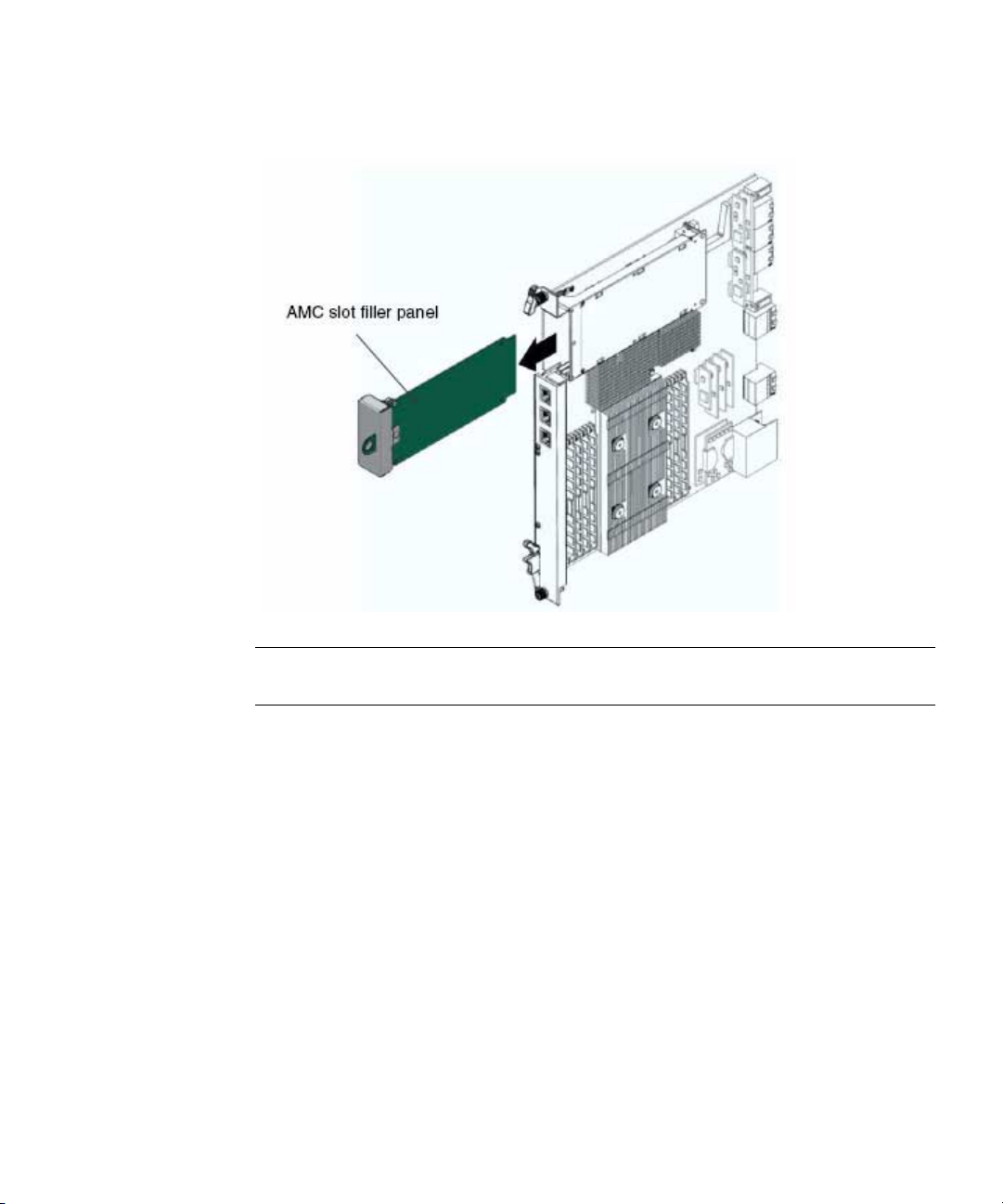
FIGURE 2-1 Removing the AMC Slot Filler Panel
Note – A module handle is at the bottom of the HBA. When you install the HBA,
the position of the module handle (pulled out or pushed in) does not matter.
Insert the HBA through the cutout and into the AMC slot (FIGURE 2-2).
3.
Chapter 2 Hardware Installation and Removal 9
Page 16

FIGURE 2-2 Inserting the HBA Into the AMC Connector
4. Carefully plug the HBA into the AMC connector (FIGURE 2-2).
Ensure that the HBA is seated correctly in the connector.
Caution – Do not use excessive force when installing the HBA into the slot. You
might damage the AMC connector on the Netra board, causing permanent damage
to the HBA or board. If the HBA does not seat properly when you apply even
pressure, remove the HBA and carefully reinstall it.
5. If the module handle was pulled out when you inserted the HBA, push the
handle all the way in.
6. If the server is powered on, the HS LED next to the module handle blinks two
or three times.
When the HS LED goes dark, the HBA is installed.
▼ To Connect the Optical Cable
Note – The HBA does not allow normal data transmission on an optical link unless
it is connected to another similar or compatible Fibre Channel (FC) product (that is,
multimode to multimode).
Use multimode fiber-optic cable that is intended for short-wave lasers. The cable
must adhere to the specifications in
10 Sun StorageTek ATCA 4Gb FC Dual Port HBA Installation Guide • April 2010
TABLE 2-1.
Page 17

TABLE 2-1 Optical Cable Specifications
Fiber-Optic Cable Maximum Length Minimum Length Connector
62.5/125 µm
(multimode)
300 meters at 1.0625 Gbps
150 meters at 2.125 Gbps
2 meters LC
70 meters at 4.25 Gbps
µm
50/125
(multimode)
500 meters at 1.0625 Gbps
300 meters at 2.125 Gbps
2 meters LC
150 meters at 4.25 Gbps
Follow these steps when connecting the optical cable:
1. Connect the fiber-optic cable to an LC connector on the HBA as shown in
FIGURE 2-3.
FIGURE 2-3 Connecting the Optical Cables
2. Connect the other end of the cable to the FC device.
Chapter 2 Hardware Installation and Removal 11
Page 18

3. Observe the port LEDs status for the power-on self test (POST) results as
shown in
TABLE 2-2 summarizes port LED indicator combinations. Refer to FIGURE 2-4 to
TABLE 2-2.
determine the location of the LEDs. Each port has a corresponding set of LEDs
that provide a visual indication of the operating state.
TABLE 2-2 Port LED Indicator Status Definitions
Green LED Yellow LED State
On 1 fast blink 1-Gb link rate - Normal operating state, link up
On 2 fast blinks 2-Gb link rate - Normal operating state, link up
On 3 fast blinks 4-Gb link rate - Normal operating state, link up
Off Off One of the following:
• Wake-up failure (failed board)
• Server not powered on
• Server not providing power to the board
Off On POST failure (failed board)
Off Slow blink Wake-up failure monitor
Off Fast blink Failure in POST
Off Flashing POST processing in progress
On Off Failure while functioning
On On Failure while functioning
Slow blink Off Normal - link down
Slow blink On Not defined
Slow blink Slow blink Off-line for download
Slow blink Fast blink Restricted off-line mode (waiting for restart)
Slow blink Flashing Restricted off-line mode, test active
12 Sun StorageTek ATCA 4Gb FC Dual Port HBA Installation Guide • April 2010
Page 19

FIGURE 2-4 LEDs
▼ To Verify the Installation (Solaris OS)
1. Use the cfgadm command to verify proper HBA installation.
% cfgadm
Ap_Id Type Receptacle Occupant Condition
c3 fc connected configured ok
c4 fc connected configured ok
pcie5 fibre/hp connected configured ok
If the HBA is properly installed and connected, you will see output similar to that
shown in the example.
2. If an HBA adapter is shown as unconfigured or disconnected, use the cfgadm
-c configure command to configure the adapter.
Chapter 2 Hardware Installation and Removal 13
Page 20

▼ To Verify Attached Storage (Solaris OS)
% cfgadm -al
Ap_Id Type Receptacle Occupant Condition
c3 fc-fabric connected configured unknown
c3::200600a0b816005e disk connected configured unknown
c3::200700a0b816005e disk connected configured unknown
c4 fc connected unconfigured unknown
pcie5 fibre/hp connected configured ok
1. Use the cfgadm -al command to verify attached storage.
If the HBA is properly installed and storage is connected properly, you will see
output similar to that shown in the example. In this example, one port of an HBA
adapter is connected through a fabric switch to two ports of a disk array.
2. If an adapter is shown as unconfigured, use the cfgadm -c configure
command to configure it.
14 Sun StorageTek ATCA 4Gb FC Dual Port HBA Installation Guide • April 2010
Page 21

Removing the Hardware
The following instructions describe the tasks required to remove the HBA. Refer to
your system installation or service manual for detailed HBA adapter removal
instructions.
The hardware removal process involves following these general steps:
1. Preparing the HBA for hot-plug removal with one of the following:
■ The module handle
■ The Solaris OS
2. Removing the AMC module hardware
▼ To Prepare the HBA for Hot-Plug Removal
Using the Module Handle
This feature is not supported at this time.
▼ To Prepare the HBA for Hot-Plug Removal
(Solaris OS)
If you want to remove the HBA without first halting the operating system and
removing power from the associated server blade, you may first prepare it for
removal as follows:
1. Use the cfgadm command to identify the HBA to be removed.
% cfgadm
Ap_Id Type Receptacle Occupant Condition
pcie5 fibre/hp connected configured ok
pcie6 fibre/hp connected configured ok
2. Use the cfgadm -c unconfigure command to unconfigure the attachment
point ID (Ap_Id) for the HBA.
Chapter 2 Hardware Installation and Removal 15
Page 22

3. Use the cfgadm -c disconnect command to prepare the HBA for removal.
A flashing Power indicator LED indicates that the HBA is being prepared for
removal. A dark Power indicator LED indicates that the HBA is ready to be
removed.
▼ To Remove the HBA Hardware
1. After the HS LED stops blinking and stays blue, pull the module lever out the
rest of the way, and pull the HBA from the slot.
FIGURE 2-5 Removing the HBA
16 Sun StorageTek ATCA 4Gb FC Dual Port HBA Installation Guide • April 2010
Page 23

CHAPTER
3
HBA Software Installation
This chapter describes the Solaris driver software that is required to support the
HBA. The chapter contains the following section:
■ “Installing Software for the Solaris OS” on page 17
■ “Installing Software for the Wind River Linux OS” on page 18
■ “Installing Software for the Red Hat Enterprise Linux OS” on page 19
Installing Software for the Solaris OS
The HBA driver is included in the Solaris 10 6/06 (s10u2) release, at minimum. This
Solaris 10 6/06 release, and later releases, require nothing from the user.
Solaris 10 1/06 (s10u1) is required to support the HBA on minimum supported
versions of Solaris for x64/x86 systems. If you are using the Solaris 10 1/06 release,
install patch 120222-21 or 120223-21 to install the HBA driver. Patches are available
at http://sunsolve.sun.com.
▼ To Install or Update the Driver From a Patch
1. Log in as the root user.
2. Navigate to the directory that contains the patch.
3. Add the latest patch by typing the following at the command prompt.
# patchadd patch-name
17
Page 24

Solaris Diagnostic Support
Diagnostic support for the HBA is included in Oracle’s SunVTS software beginning
with version 6.3. SunVTS is included with the Solaris 10 11/06 (s10u3) release and is
also available for download at:
http://www.sun.com/oem/products/vts
The emlxtest utility, provided as part of the SunVTS software, supports the
following functions:
■ Connectivity verification
■ Firmware version and checksum testing
■ Self testing
■ Loopback tests
■ External
■ Internal, single-bit
■ Internal, 10-bit
■ Mailbox
Installing Software for the Wind River Linux OS
The HBA driver is included in the supported version of the Wind River Linux OS.
However, you must use the Wind River development kit to create a version of Wind
River Linux that supports your hardware environment, which includes this HBA.
▼ To Obtain the Wind River Development Kit
1. Go to the customer support area of the Wind River website at:
http://www.windriver.com/support/
2. Contact Wind River customer support to purchase a development kit that is
specific to your hardware environment.
The devlopment kit enables you to create a version of Wind River Linux that
supports your hardware environment.
18 Sun StorageTek ATCA 4Gb FC Dual Port HBA Installation Guide • April 2010
Page 25

Note – When you contact Wind River customer support, be sure to specify all
components in your hardware environment (including this HBA). This will ensure
you receive all software that is required to run in the hardware environment.
Installing Software for the Red Hat Enterprise Linux OS
No updates are required to support the HBA on minimum supported versions of the
Red Hat Enterprise Linux OS.
For diagnostic support, you might need to rebuild the Linux driver. Before
rebuilding the driver for Linux, you must have the required Linux OS installed on
the hard disk.
The driver and management utilities are available for download at the Emulex
support site for Sun Microsystems.
▼ To Install the HBA Software for the Linux OS
1. Go to the Emulex support site for Oracle at:
http://www.emulex.com/downloads/sun.html
2. Locate the Sun StorageTek section and click the model number for this HBA.
3. Locate the Linux Driver section and click the link to the driver for the
appropriate version of Linux.
4. Click the driver kit Download icon to copy the driver to a local file system.
5. Click the applications kit Download icon to copy the management utilities to a
local file system.
6. Click each of the manual icons to open the associated user manual.
7. Install the driver for Linux as described in the Emulex driver user manual.
8. Install the management utilities as described in the Emulex utilities user
manual.
Chapter 3 HBA Software Installation 19
Page 26

20 Sun StorageTek ATCA 4Gb FC Dual Port HBA Installation Guide • April 2010
Page 27

CHAPTER
4
Known Issues
This chapter contains any known issues with the HBA. The chapter contains the
following topic:
■ “Potential AMC I/O Card Corruption” on page 21
Potential AMC I/O Card Corruption
Issue: If you are using Oracle’s Sun Netra CT900 ATCA Blade Server or are using
any Pigeon Point Systems Shelf Manager, the Shelf Manager will corrupt any AMC
I/O cards when the Shelf Manager firmware is not at the latest version. The Shelf
Manager firmware must be the latest version available from Oracle’s Download
Center (for an Oracle chassis) or from Pigeon Point Systems (for a non-Oracle
chassis).
Workaround: To prevent corruption, DO NOT insert any AMC I/O cards into the
chassis until you have upgraded the Shelf Manager firmware to the latest available
version.
Note – Only Oracle configurations, as described in “System Interoperability” on
page 3, are supported. Use of this product in non-supported configurations is done
at your own risk.
To obtain the latest firmware, do either of the following:
● If you have an Oracle ATCA chassis, download the latest Shelf Manager
firmware (R3HW1) from Oracle at:
http://www.sun.com/download/products.xml?id=47269dbb
21
Page 28

● If you have a non-Oracle ATCA chassis, contact Pigeon Point Systems
customer support for information about downloading the latest firmware
version:
http://www.pigeonpoint.com/contact.html
You can also contact Pigeon Point Systems customer support at:
support@pigeonpoint.com
22 Sun StorageTek ATCA 4Gb FC Dual Port HBA Installation Guide • April 2010
Page 29

APPENDIX
A
Declaration of Conformity, Safety, and Regulatory Statements
This appendix provides Declaration of Conformity, safety, and regulatory statements
for the HBA.
The appendix contains the following topics:
■ “Declaration of Conformity” on page 25
■ “Safety Agency Compliance Statements” on page 27
■ “Regulatory Compliance Statements” on page 41
23
Page 30

24 Sun StorageTek ATCA 4Gb FC Dual Port HBA Installation Guide • April 2010
Page 31

Declaration of Conformity
To receive a copy of the latest Declaration of Conformity (DoC) for the product, either contact your
local Oracle sales representative, or create an online request at:
https://www2.sun.de/dct/forms/reg_us_1607_755_0.jsp
25
Page 32

26 Sun StorageTek ATCA 4Gb FC Dual Port HBA Installation Guide • April 2010
Page 33

Safety Agency Compliance Statements
Read this section before beginning any procedure. The
following text provides safety precautions to follow when
installing an Oracle product.
Safety Precautions
For your protection, observe the following safety
precautions when setting up your equipment:
■ Follow all cautions and instructions marked on the
equipment.
■ Ensure that the voltage and frequency of your power
source match the voltage and frequency inscribed on
the equipment’s electrical rating label.
■ Never push objects of any kind through openings in
the equipment. Dangerous voltages may be present.
Conductive foreign objects could produce a short
circuit that could cause fire, electric shock, or damage
to your equipment.
■ This product is intended for restricted access whereby
access is controlled through the use of a means of
security (for example, key, lock, tool, badge access)
and personnel authorized for access have been
instructed on the reasons for the restrictions and any
precautions that need to be taken.
Depending on the type of power switch your device has,
one of the following symbols may be used:
On – Applies AC power to the system.
Off – Removes AC power from the system.
Standby – The On/Standby switch is in the
standby position.
Modifications to Equipment
Do not make mechanical or electrical modifications to the
equipment. Sun Microsystems is not responsible for
regulatory compliance of a modified Sun product.
Placement of a Sun Product
Caution – Do not block or cover the openings
of your Sun product. Never place a Sun
product near a radiator or heat register.
Failure to follow these guidelines can cause
overheating and affect the reliability of your
Sun product.
Symbols
The following symbols may appear in this book:
Caution – There is a risk of personal injury
and equipment damage. Follow the
instructions.
Caution – Hot surface. Avoid contact.
Surfaces are hot and may cause personal
injury if touched.
Caution – Hazardous voltages are present. To
reduce the risk of electric shock and danger to
personal health, follow the instructions.
SELV Compliance
Safety status of I/O connections comply to SELV
requirements.
Power Cord Connection
Caution – Sun products are designed to work
with power systems having a grounded
neutral (grounded return for DC-powered
products). To reduce the risk of electric shock,
do not plug Sun products into any other type
of power system. Contact your facilities
manager or a qualified electrician if you are
not sure what type of power is supplied to
your building.
27
Page 34

Caution – Not all power cords have the same
current ratings. Do not use the power cord
provided with your equipment for any other
products or use. Household extension cords
do not have overload protection and are not
meant for use with computer systems. Do not
use household extension cords with your Sun
product.
The following caution applies only to devices with a
Standby power switch:
Caution – The power switch of this product
functions as a standby type device only. The
power cord serves as the primary disconnect
device for the system. Be sure to plug the
power cord into a grounded power outlet that
is nearby the system and is readily accessible.
Do not connect the power cord when the
power supply has been removed from the
system chassis.
The followingcaution applies only to deviceswith multiple
power cords:
Caution – For products with multiple power
cords, all power cords must be disconnected
to completely remove power from the system.
Battery Warning
Caution – There is danger of explosion if
batteries are mishandled or incorrectly
replaced. On systems with replaceable
batteries, replace only with the same
manufacturer and type or equivalent type
recommended by the manufacturer per the
instructions provided in the product service
manual. Do not disassemble batteries or
attempt to recharge them outside the system.
Do not dispose of batteries in fire. Dispose of
batteries properly in accordance with the
manufacturer’s instructions and local
regulations. Note that on Sun CPU boards,
there is a lithium battery molded into the realtime clock. These batteries are not customer
replaceable parts.
28 Sun StorageTek ATCA 4Gb FC Dual Port HBA Installation Guide • April 2010
Page 35

Energy Storage Module Caution
Caution – There is a danger of shock or
equipment damage if energy storage modules
are mishandled or incorrectly replaced. When
replacing the energy storage modules, use
only replacement modules that have been
provided by Sun Microsystems, following the
instructions provided in the product service
manual. Do not disassemble modules or
attempt to recharge them outside of the
system. Do not dispose of the modules;
instead, return them to Sun Microsystems in
accordance with Sun procedures for the
product
System Unit Cover
You must remove the cover of your Sun computer system
unit to add cards, memory, or internal storage devices. Be
sure toreplace the cover before powering on yourcomputer
system.
Caution – Do not operate Sun products
without the cover in place. Failure to take this
precaution may result in personal injury and
system damage.
Rack System Instructions
The following or similar rack-mount instructions are
included with the installation instructions:
■ Elevated Operating Ambient – If installed in a closed
or multi-unit rack assembly, the operating ambient
temperature of the rack environment may be greater
than room ambient. Therefore, consideration should
be given to installing the equipment in an
environment compatible with the maximum ambient
temperature (Tma) specified by the manufacturer.
■ Reduced Air Flow – Installation of the equipment in a
rack should be such that the amount of air flow
required for safe operation of the equipment is not
compromised.
■ Mechanical Loading – Mounting of the equipment in
the rack should be such that a hazardous condition is
not achieved due to uneven mechanical loading.
■ Circuit Overloading – Consideration should be given
to the connection of the equipment to the supply
circuit and the effect that overloading of the circuits
might have on overcurrent protection and supply
wiring. Appropriate consideration of equipment
nameplate ratings should be used when addressing
this concern.
■ Reliable Earthing – Reliable earthing of rack-mounted
equipment should be maintained. Particular attention
should be given to supply connections other than
direct connections to the branch circuit (for example,
use of power strips).
Caution – Slide/rail mounted equipment
must not be used as a shelf or workspace.
Rack System Warning
The following warnings apply to Racks and Rack Mounted
systems.
Caution – For safety, equipment should
always be loaded from the bottom up. That is,
install the equipment that will be mounted in
the lowest part of the rack first, then the next
higher systems, etc.
Caution – To prevent the rack from tipping
during equipment installation, the anti-tilt bar
on the rack must be deployed.
Caution – To prevent extreme operating
temperature within the rack insure that the
maximum temperature does not exceed the
product’s ambient rated temperatures.
Caution – To prevent extreme operating
temperatures due to reduced airflow
consideration should be made to the amount
of air flow that is required for a safe operation
of the equipment.
Safety Agency Compliance Statements 29
Page 36

Laser Compliance Notice
Sun products that use laser technology comply withClass 1
laser requirements.
■ Ce produit est destiné à être utilisé dans des zones à
accès limité, dans lesquelles les accès sont contrôlés
au moyen de systèmes de sécurité (par exemple, à clé,
verrou, dispositif ou badge). Le personnel autorisé à
accéder à ces zones doit avoir été préalablement
informé des raisons justifiant la limitation des accès et
de toutes les précautions à prendre.
Symboles
Vous trouverez ci-dessous la signification des différents
symboles utilisés:
CD and DVD Devices
The following caution applies to CD, DVD, and other
optical devices.
Caution – Use of controls, adjustments, or the
performance of procedures other than those
specified herein may result in hazardous
radiation exposure.
Conformité aux normes de sécurité
Veuillez lire attentivement cette section avant de
commencer. Ce texte traite des mesures de sécurité qu’il
convient de prendre pour l’installation d’un produit Sun
Microsystems.
Mesures de sécurité
Pour votre sécurité, nous vous recommandons de suivre
scrupuleusement lesmesures de sécuritéci-dessous lorsque
vous installez votre matériel:
■ Suivez tous les avertissements et toutes les
instructions inscrites sur le matériel.
■ Assurez-vous que la tension et la fréquence de votre
source d'alimentation correspondent à la tension et à
la fréquence indiquées sur l'étiquette de la tension
électrique nominale du matériel
■ N'introduisez jamais d'objets quels qu'ils soient dans
les ouvertures de l'équipement. Vous pourriez vous
trouver en présence de hautes tensions dangereuses.
Tout objet étranger conducteur risque de produire un
court-circuit pouvant présenter un risque d'incendie
ou de décharge électrique, ou susceptible
d'endommager le matériel.
Attention – Vous risquez d'endommager le
matériel ou de vous blesser. Veuillez suivre les
instructions.
Attention – Surfaces brûlantes. Evitez tout
contact. Les surfaces sont brûlantes. Vous
risquez de vous blesser si vous les touchez.
Attention – Tensions dangereuses. Pour
réduire les risques de décharge électrique et
de danger physique, observez les consignes
indiquées.
Selon le type d'interrupteur marche/arrêt dont votre
appareil est équipé, l'un des symboles suivants sera utilisé:
Marche – Met le système sous tension
alternative.
Arret – Met le système hors tension
alternative.
Veilleuse – L'interrupteur Marche/Veille est
sur la position de veille.
Modification du matériel
N'apportez aucune modification mécanique ou électrique
au matériel. Sun Microsystems décline toute responsabilité
quant à la non-conformité éventuelle d'un produit Sun
modifié.
30 Sun StorageTek ATCA 4Gb FC Dual Port HBA Installation Guide • April 2010
Page 37

Positionnement d’un produit Sun
Attention – Evitez d'obstruer ou de recouvrir
les orifices de votre produit Sun. N'installez
jamais un produit Sun près d'un radiateur ou
d'une source de chaleur. Si vous ne respectez
pas ces consignes, votre produit Sun risque de
surchauffer et son fonctionnement en sera
altéré.
Conformité SELV
Le niveau de sécurité des connexions E/S est conforme aux
normes SELV.
Connexion du cordon d’alimentation
Attention – Les produits Sun sont conçus
pour fonctionner avec des systèmes
d'alimentation équipés d'un conducteur
neutre relié à la terre (conducteur neutre pour
produits alimentés en CC). Pour réduire les
risques de décharge électrique, ne branchez
jamais les produits Sun sur une source
d'alimentation d'un autre type. Contactez le
gérant de votre bâtiment ou un électricien
agréé si vous avez le moindre doute quant au
type d'alimentation fourni dans votre
bâtiment.
Attention – Tous les cordons d'alimentation
ne présentent pas les mêmes caractéristiques
électriques. Les cordons d'alimentation à
usage domestique ne sont pas protégés contre
les surtensions et ne sont pas conçus pour être
utilisés avec des ordinateurs. N'utilisez jamais
de cordon d'alimentation à usage domestique
avec les produits Sun.
système. Assurez-vous de le brancher dans
une prise d'alimentation mise à la terre près
du système et facile d'accès. Ne le branchez
pas lorsque l'alimentation électrique ne se
trouve pas dans le châssis du système.
L'avertissement suivant s'applique uniquement aux
systèmes équipés de plusieurs cordons d'alimentation:
Attention – Pour mettre un système équipé de
plusieurs cordons d'alimentation hors tension,
il est nécessaire de débrancher tous les
cordons d'alimentation.
Mise en garde relative aux batteries
Attention – Les batteries risquent d’exploser
en cas de manipulation maladroite ou de
remplacement incorrect. Pour les systèmes
dont les batteries sont remplaçables, effectuez
les remplacements uniquement selon le
modèle du fabricant ou un modèle équivalent
recommandé par le fabricant, conformément
aux instructions fournies dans le manuel de
service du système. N’essayez en aucun cas de
démonter les batteries, ni de les recharger hors
du système. Ne les jetez pas au feu. Mettez-les
au rebut selon les instructions du fabricant et
conformément à la législation locale en
vigueur. Notez que sur les cartes processeur
de Sun, une batterie au lithium a été moulée
dans l'horloge temps réel. Les batteries ne sont
pas des pièces remplaçables par le client.
L'avertissement suivant s'applique uniquement aux
systèmes équipés d'un interrupteur Veille:
Attention – L'interrupteur d'alimentation de
ce produit fonctionne uniquement comme un
dispositif de mise en veille. Le cordon
d'alimentation constitue le moyen principal de
déconnexion de l'alimentation pour le
Avertissement - Module de stockage d’énergie
Attention – Si vous manipulez ou remplacez
les modules de stockage d’énergie
incorrectement, vous risquez de les
Safety Agency Compliance Statements 31
Page 38

endommager ou de vous exposer à un choc
électrique. Remplacez les modules de stockage
d’énergie uniquement par les modules de
remplacement que Sun Microsystems fournit,
en veillant à respecter les instructions
indiquées dans le manuel d’entretien du
produit. Ne démontez pas les modules.
N’essayez pas de les recharger hors du
système. Ne jetez pas les modules, mais
retournez-les à Sun Microsystems
conformément aux procédures Sun relatives
au produit.
Couvercle de l'unité
Pour ajouterdes cartes,de la mémoire ou des périphériques
de stockage internes, vous devez retirer le couvercle de
votre système Sun. Remettez le couvercle supérieur en
place avant de mettre votre système sous tension.
Attention – Ne mettez jamais des produits
Sun sous tension si leur couvercle supérieur
n'est pas mis en place. Si vous ne prenez pas
ces précautions, vous risquez de vous blesser
ou d'endommager le système.
conséquences d'une éventuelle surcharge des circuits
sur la protection de surintensité et sur le câblage
d'alimentation. En l'occurrence, les valeurs nominales
de la plaque signalétique du matériel doivent être
prises en compte.
■ Mise à la terre fiable : une mise à la terre fiable du
matériel monté en rack doit être assurée. Une
attention toute particulière est requise pour les
raccordements d'alimentation autres que ceux
effectués directement sur le circuit principal (par
exemple, en cas d'utilisation de blocs multiprises).
Attention – L’équipement monté sur
glissière/rail ne doit servir ni d’étagère ni
d’espace de travail.
Mise en garde relative au système en rack
La mise en garde suivante s'applique aux racks et aux
systèmes montés en rack.
Instructions de montage en rack
Les instructions de montage en rack suivantes ou similaires
à celles-ci sont fournies avec les instructions d'installation :
■ Température ambiante de fonctionnement élevée :en
cas d'installation dans un châssis fermé ou contenant
plusieurs appareils, la température ambiante de
fonctionnement au niveau du rack peut être
Attention – Pour des raisons de sécurité, le
matériel doit toujours être chargé du bas vers
le haut. En d'autres termes, vous devez
installer, en premier, le matériel qui doit se
trouver dans la partie la plus inférieure du
rack, puis installer le matériel sur le niveau
suivant, etc.
supérieure à la température ambiante de la pièce. En
conséquence, il convient de veiller à installer le
matériel dans un environnement compatible avec la
température ambiante maximale (Tma), spécifiée par
le fabricant.
■ Débit d'air réduit : l'installation du matériel dans un
Attention – Afin d'éviter que le rack ne
penche pendant l'installation du matériel, tirez
la barre anti-basculement du rack.
rack doit être effectuée de façon à ne pas
compromettre le débit d'air nécessaire pour un
fonctionnement sûr de ce matériel.
■ Charge mécanique : le montage de l'équipement en
rack doit être réalisé de manière à éviter toute
situation dangereuse résultant d'une charge
déséquilibrée.
■ Surcharge de circuit : il convient de prendre les
Attention – Pour éviter des températures de
fonctionnement extrêmes dans le rack,
assurez-vous que la température maximale ne
dépasse pas la fourchette de températures
ambiantes du produit déterminée par le
fabricant.
précautions nécessaires pour la connexion du matériel
au circuit d'alimentation et de réfléchir aux
32 Sun StorageTek ATCA 4Gb FC Dual Port HBA Installation Guide • April 2010
Page 39

Attention – Afin d'empêcher des
températures de fonctionnement extrêmes
provoquées par une aération insuffisante,
assurez-vous de fournir une aération
appropriée pour un fonctionnement du
matériel en toute sécurité
Avis de conformité des appareils laser
Les produitsSun quifont appelaux technologieslasers sont
conformes aux normes de la classe 1 en la matière.
Périphériques CD et DVD
L'avertissement suivant s'applique aux périphériques CD,
DVD et autres périphériques optiques:
Attention – L'utilisation de contrôles et de
réglages ou l'application de procédures autres
que ceux spécifiés dans le présent document
peuvent entraîner une exposition à des
radiations dangereuses.
■ Stellen Sie sicher, dass Spannung und Frequenz der
Stromversorgung den Nennleistungen auf dem am
Gerät angebrachten Etikett entsprechen.
■ Führen Sie niemals Fremdobjekte in die Öffnungen
am Gerät ein. Es können gefährliche Spannungen
anliegen. Leitfähige Fremdobjekte können einen
Kurzschluss verursachen, der einen Brand, Stromschlag oder Geräteschaden herbeiführen kann.
■ Dieses Produkt unterliegt Zugangsbeschränkungen.
Der Zugang wird mithilfe eines Sicherheitsmechanismus kontrolliert (z. B. einem Schlüssel, einer
Sperre, einem Tool oder eines Werksausweises) und
das autorisierte Zugangspersonal wurde über die
Gründe für die Beschränkungen und die zu
treffenden Sicherheitsmaßnahmen unterrichtet.
Symbole
Die Symbole in diesem Handbuch haben folgende
Bedeutung:
Achtung – Gefahr von Verletzung und
Geräteschaden. Befolgen Sie die Anweisungen.
Achtung – Heiße Oberfläche. Nicht berühren,
da Verletzungsgefahr durch heiße Oberfläche
besteht.
Achtung – Gefährliche Spannungen. Befolgen
Sie die Anweisungen, um Stromschläge und
Verletzungen zu vermeiden.
Einhaltung sicherheitsbehördlicher Vorschriften
Lesen Sie vor dem Ausführen von Arbeiten diesen
Abschnitt. Im folgenden Text werden Sicherheitsvorkehrungen beschrieben, die Sie bei der Installation eines
Sun Microsystems-Produkts beachten müssen.
Sicherheitsvorkehrungen
Treffen Sie zu Ihrem eigenen Schutzbei der Installation des
Geräts die folgenden Sicherheitsvorkehrungen:
■ Beachten Sie alle auf den Geräten angebrachten
Warnhinweise und Anweisungen.
Je nach Netzschaltertyp an Ihrem Gerät kann eines der
folgenden Symbole verwendet werden:
Ein – Versorgt das System mit Wechselstrom.
Aus– Unterbricht die Wechselstromzufuhr
zum Gerät.
Wartezustand – Der Ein-/Standby-Netzschalter befindet sich in der Standby-Position.
Safety Agency Compliance Statements 33
Page 40

Modifikationen des Geräts
Nehmen Sie keine elektrischen oder mechanischen
Gerätemodifikationen vor. Sun Microsystems ist für die
Einhaltung der Sicherheitsvorschriften von modifizierten
Sun-Produkten nicht haftbar.
Aufstellung von Sun-Geräten
Achtung – Geräteöffnungen Ihres SunProdukts dürfen nicht blockiert oder
abgedeckt werden. Sun-Geräte sollten niemals
in der Nähe von Heizkörpern oder Heißluftklappen aufgestellt werden. Die Nichtbeachtung dieser Richtlinien kann Überhitzung
verursachen und die Zuverlässigkeit Ihres
Sun-Geräts beeinträchtigen.
SELV-Konformität
Der Sicherheitsstatus der E/A-Verbindungen entspricht
den SELV-Anforderungen.
Anschluss des Netzkabels
Achtung – Sun-Geräte sind für
Stromversorgungssysteme mit einem
geerdeten neutralen Leiter (geerdeter
Rückleiter bei gleichstrombetriebenen
Geräten) ausgelegt. Um die Gefahr von
Stromschlägen zu vermeiden, schließen Sie
das Gerät niemals an andere Stromversorgungssysteme an. Wenden Sie sich an den
zuständigen Gebäudeverwalter oder an einen
qualifizierten Elektriker, wenn Sie nicht sicher
wissen, an welche Art von Stromversorgungssystem Ihr Gebäude angeschlossen ist.
Achtung – Nicht alle Netzkabel verfügen
über die gleichen Nennwerte. Herkömmliche,
im Haushalt verwendete Verlängerungskabel
besitzen keinen Überlastschutz und sind
daher für Computersysteme nicht geeignet.
Verwenden Sie bei Ihrem Sun-Produkt keine
Haushalts-Verlängerungskabel.
Die folgende Warnung gilt nur für Geräte mit StandbyNetzschalter:
Achtung – Beim Netzschalter dieses Geräts
handelt es sich nur um einen Ein/StandbySchalter. Zum völligen Abtrennen des Systems
von der Stromversorgung dient hauptsächlich
das Netzkabel. Stellen Sie sicher, dass das
Netzkabel an eine frei zugängliche geerdete
Steckdose in der Nähe des Systems angeschlossen ist. Schließen Sie das Stromkabel
nicht an, wenn die Stromversorgung vom
Systemchassis entfernt wurde.
Die folgende Warnung gilt nur für Geräte mit mehreren
Netzkabeln:
Achtung – Bei Produkten mit mehreren Netzkabeln müssen alle Netzkabel abgetrennt werden, um das System völlig von der Stromversorgung zu trennen.
Warnung bezüglich Batterien
Achtung – Bei unsachgemäßer Handhabung
oder nicht fachgerechtem Austausch der
Batterien besteht Explosionsgefahr. Verwenden Sie bei Systemen mit austauschbaren
Batterien ausschließlich Ersatzbatterien
desselben Typs und Herstellers bzw. einen
entsprechenden, vom Hersteller gemäß den
Anweisungen im Service-Handbuch des
Produkts empfohlenen Batterietyp. Versuchen
Sie nicht, die Batterien auszubauen oder
außerhalb des Systems wiederaufzuladen.
Werfen Sie die Batterien nicht ins Feuer.
Entsorgen Sie die Batterien entsprechend den
Anweisungen des Herstellers und den vor Ort
geltenden Vorschriften. CPU-Karten von Sun
verfügen über eine Echtzeituhr mit integrierter Lithiumbatterie. Diese Batterie darf nur
von einem qualifizierten Servicetechniker ausgewechselt werden.
34 Sun StorageTek ATCA 4Gb FC Dual Port HBA Installation Guide • April 2010
Page 41

Sicherheitshinweise zum Energiespeichermodul
Achtung – Bei unsachgemäßer Handhabung
oder unsachgemäßem Austausch von
Energiespeichermodulen besteht die Gefahr
eines Stromschlags oder Geräteschadens.
Verwenden Sie beim Austausch von
Energiespeichermodulen nur Ersatzmodule,
die von Sun Microsystems bereitgestellt
wurden, und folgen Sie den im Service
Manual zum Produkt enthaltenen
Anweisungen. Versuchen Sie auf keinen Fall,
Module auszubauen oder diese außerhalb des
Systems wiederaufzuladen. Entsorgen Sie die
Module bitte nicht. Geben Sie sie stattdessen
an Sun Microsystems gemäß den SunVerfahren für das Produkt zurück.
Gehäuseabdeckung
Sie müssen die Abdeckung Ihres Sun-Computersystems
entfernen, um Karten, Speicher oderinterne Speichergeräte
hinzuzufügen. Bringen Sie vor dem Einschalten des
Systems die Gehäuseabdeckung wieder an.
■ Mechanische Belastung - Die Montage des Geräts im
Rack sollte so erfolgen, dass bei einer
ungleichmäßigen mechanischen Belastung keine
gefährliche Betriebsbedingung entstehen kann.
■ Stromkreisüberlastung - Der Anschluss des Geräts an
den Speisestromkreis und die Wirkung, die ein
Überlasten der Stromkreise auf das ÜberstromschutzGerät und die Speisestromkreisverkabelung haben
kann, sollten sorgfältig geprüft und berücksichtigt
werden. Beim Behandeln dieses Aspekts sollten
besonders die Lastangaben auf dem Leistungsschild
des Geräts sorgfältig geprüft werden.
■ Zuverlässige Erdung - Ausrüstung, die in Racks
montiert ist, muss zuverlässig geerdet sein. Besonders
müssen hierbei die Stromanschlussleitungen und weniger die direkten Verbindungen
zum Abzweigstromkreis beachtet werden (z. B. durch
die Verwendung von Adapterleisten).
Achtung – Verwenden Sie Geräte in
Steckplätzen bzw. auf Schienen nicht als Regal
oder Arbeitsbereich.
Achtung – Nehmen Sie Sun-Geräte nicht ohne
Abdeckung in Betrieb. Die Nichtbeachtung
dieses Warnhinweises kann Verletzungen oder
Geräteschaden zur Folge haben.
Anweisungen zur Rack-Montage
Die folgenden oder ähnlichen Anweisungen zur RackMontage wurden in die Installationsanweisungen
aufgenommen:
■ Erhöhte Betriebsumgebungstemperatur - Wenn das
Rack in einer geschlossenen Rack-Baugruppe oder in
einer Multi-unit-Rack-Baugruppe installiert ist, kann
die Betriebsumgebungstemperatur der RackUmgebung höher sein als die Umgebungstemperatur
des Raumes. Deshalb sollte berücksichtigt werden,
das Gerät in einer Umgebung zu installieren, die
kompatibel zu der vom Hersteller angegebenen
maximalen Umgebungstemperatur (Tma) ist.
■ Reduzierter Luftstrom - Die Installation des Geräts in
einem Rack sollte so erfolgen, dass die
Luftstrommenge, die für den sicheren Betrieb des
Geräts erforderlich ist, nicht beeinträchtigt wird.
Safety Agency Compliance Statements 35
Page 42

Warnungen bezüglich in Racks eingebauter Systeme
Die folgenden Warnungen gelten für Racks und in Racks
eingebaute Systeme:
Achtung – Aus Sicherheitsgründen sollten
sämtliche Geräte von unten nach oben in
Racks eingebaut werden. Installieren Sie also
zuerst die Geräte, die an der untersten
Position im Rack eingebaut werden, gefolgt
von den Systemen, die an nächsthöherer Stelle
eingebaut werden, usw.
Achtung – Verwenden Sie beim Einbau den
Kippschutz am Rack, um ein Umkippen zu
vermeiden.
Achtung – Um extreme Betriebstemperaturen
im Rack zu vermeiden, stellen Sie sicher, dass
die Maximaltemperatur die Nennleistung der
Umgebungstemperatur für das Produkt nicht
überschreitet
Achtung – Um extreme Betriebstemperaturen
durch verringerte Luftzirkulation zu vermeiden, sollte die für den sicheren Betrieb des
Geräts erforderliche Luftzirkulation eingesetzt
werden.
Hinweis zur Laser-Konformität
Sun-Produkte, die die Laser-Technologie verwenden,
entsprechen den Laser-Anforderungen der Klasse 1.
CD- und DVD-Geräte
Die folgende Warnung gilt für CD-, DVD- und andere
optische Geräte:
Achtung – Die hier nicht aufgeführte
Verwendung von Steuerelementen,
Anpassungen oder Ausführung von
Vorgängen kann eine gefährliche
Strahlenbelastung verursachen.
Normativas de seguridad
Lea esta sección antes de realizar cualquier operación. En
ella se explican las medidasde seguridad que debe tomaral
instalar un producto de Sun Microsystems.
Medidas de seguridad
Para su protección, tome las medidas de seguridad
siguientes durante la instalación del equipo:
■ Siga todos los avisos e instrucciones indicados en el
equipo.
■ Asegúrese de que el voltaje y frecuencia de la fuente
de alimentación coincidan con el voltaje y frecuencia
indicados en la etiqueta de clasificación eléctrica del
equipo.
■ No introduzca objetos de ningún tipo por las rejillas
del equipo, ya que puede quedar expuesto a voltajes
peligrosos. Los objetos conductores extraños pueden
producir cortocircuitos y, en consecuencia, incendios,
descargas eléctricas o daños en el equipo.
■ Este producto se ha concebido para un acceso
restringido y, por tanto, éste se controla mediante
mecanismos de seguridad (p. ej., acceso con clave,
bloqueo, herramienta y tarjeta de identificación). Las
personas con acceso autorizado están al corriente de
los motivos de esta restricción y de las precauciones
que se deben tomar.
Símbolos
En este documento aparecen los siguientes símbolos:
Precaución – Existe el riesgo de que se
produzcan lesiones personales y daños en el
equipo. Siga las instrucciones.
36 Sun StorageTek ATCA 4Gb FC Dual Port HBA Installation Guide • April 2010
Page 43

Precaución – Superficie caliente. Evite todo
contacto. Las superficies están calientes y
pueden causar lesiones personales si se tocan.
Precaución – Voltaje peligroso. Para reducir
el riesgo de descargas eléctricas y lesiones
personales, siga las instrucciones.
En función del tipo de interruptor de alimentación del que
disponga el dispositivo, se utilizará uno de los símbolos
siguientes:
Encendido – Suministra alimentación de CA
al sistema.
Apagado – Corta la alimentación de CA del
sistema.
Espera – El interruptor de encendido/espera
está en la posición de espera.
Modificaciones en el equipo
No realicemodificaciones de tipo mecánico ni eléctrico en el
equipo. Sun Microsystems no se hace responsable del
cumplimiento de normativas en caso de que un producto
Sun se haya modificado.
Colocación de un producto Sun
Precaución – No obstruya ni tape las rejillas
del producto Sun. Nunca coloque un producto
Sun cerca de radiadores ni fuentes de calor. Si
no sigue estas indicaciones, el producto Sun
podría sobrecalentarse y la fiabilidad de su
funcionamiento se vería afectada.
Conexión del cable de alimentación
Precaución – Los productos Sun se han
diseñado para funcionar con sistemas de
alimentación que cuenten con un conductor
neutro a tierra (con conexión a tierra de
regreso para los productos con alimentación
de CC). Para reducir el riesgo de descargas
eléctricas, no conecte ningún producto Sun a
otro tipo de sistema de alimentación. Póngase
en contacto con el encargado de las
instalaciones de su empresa o con un
electricista cualificado en caso de que no esté
seguro del tipo de alimentación del que se
dispone en el edificio.
Precaución – No todos los cables de
alimentación tienen la misma clasificación
eléctrica. Los alargadores de uso doméstico no
cuentan con protección frente a sobrecargas y
no están diseñados para su utilización con
sistemas informáticos. No utilice alargadores
de uso doméstico con el producto Sun.
La siguiente medida solamente se aplica a aquellos
dispositivos que dispongan de un interruptor de
alimentación de espera:
Precaución – El interruptor de alimentación
de este producto funciona solamente como un
dispositivo de espera. El cable de alimentación
hace las veces de dispositivo de desconexión
principal del sistema. Asegúrese de que
conecta el cable de alimentación a una toma
de tierra situada cerca del sistema y de fácil
acceso. No conecte el cable de alimentación si
la unidad de alimentación no se encuentra en
el bastidor del sistema.
La siguiente medida solamente se aplica a aquellos
dispositivos que dispongan de varios cables de
alimentación:
Cumplimiento de la normativa para instalaciones SELV
Las condiciones de seguridad de las conexiones de entrada
y salidacumplen los requisitos para instalaciones SELV (del
inglés Safe Extra Low Voltage, voltaje bajo y seguro).
Safety Agency Compliance Statements 37
Page 44

Precaución – En los productos que cuentan
con varios cables de alimentación, debe
desconectar todos los cables de alimentación
para cortar por completo la alimentación
eléctrica del sistema.
servicio del producto. No desmonte módulos
ni intente recargarlos fuera del sistema. No
elimine los módulos. En su lugar, devuélvalos
a Sun Microsystems de conformidad con los
procedimientos de Sun para el producto.
Cubierta de la unidad del sistema
Debe extraer la cubierta de la unidad del sistema
informático Sun para instalar tarjetas, memoria o
dispositivos de almacenamiento internos. Vuelva a colocar
la cubierta antes de encender el sistema informático.
Advertencia sobre las baterías
Precaución – Si las baterías no se manipulan
o reemplazan correctamente, se corre el riesgo
de que estallen. En los sistemas que cuentan
con baterías reemplazables, reemplácelas sólo
con baterías del mismo fabricante y el mismo
tipo, o un tipo equivalente recomendado por
el fabricante, de acuerdo con las instrucciones
descritas en el manual de servicio del
producto. No desmonte las baterías ni intente
recargarlas fuera del sistema. No intente
deshacerse de las baterías echándolas al fuego.
Deshágase de las baterías correctamente de
acuerdo con las instrucciones del fabricante y
las normas locales. Tenga en cuenta que en las
placas CPU de Sun, hay una batería de litio
incorporada en el reloj en tiempo real. Los
usuarios no deben reemplazar este tipo de
baterías.
Advertencia relativa al módulo de almacenamiento de energía
Precaución – Existe un peligro de
electrocuciones o daños en el equipo si se
manipulan o sustituyen incorrectamente los
módulos de almacenamiento de energía.
Cuando cambie los módulos de
almacenamiento de energía, utilice
exclusivamente módulos de sustitución que
hayan sido suministrados por Sun
Microsystems, de conformidad con las
instrucciones indicadas en el manual de
Precaución – No ponga en funcionamiento
los productos Sun que no tengan colocada la
cubierta. De lo contrario, puede sufrir lesiones
personales y ocasionar daños en el sistema.
Instrucciones para el montaje en armario
Las siguientes instrucciones de montaje en armario u otras
similares se incluyen en las instrucciones de instalación:
■ Temperatura de funcionamiento elevada - si se instala
en un armario cerrado o con más unidades, la
temperatura ambiente de funcionamiento del entorno
del armario puede ser superior a la de la habitación.
Por tanto, el equipo debería instalarse en un entorno
compatible con la temperatura ambiente máxima
(Tma) especificada por el fabricante.
■ Flujo de aire reducido - para instalar el equipo en un
armario hay que asegurarse de que se mantendrá el
flujo de aire necesario para el correcto funcionamiento
del equipo.
■ Carga mecánica - el montaje del equipo en el armario
debería realizarse de modo que no se dé una situación
de peligro debido a una carga mecánica irregular.
■ Sobrecarga del circuito - debe prestarse atención a la
conexión del equipo al circuito de alimentación y a las
consecuencias que puede tener la sobrecarga de los
circuitos en la protección de sobrecorriente y el
cableado de alimentación. En caso de sobrecarga, es
recomendable tener en cuenta la potencia del equipo
que aparece en la placa de identificación.
■ Puesta a tierra fiable - debería mantenerse una puesta
a tierra fiable del equipo montado en un armario.
Debería prestarse especial atención a las conexiones
de suministro que no sean las directas al circuito
derivado (p. ej., las regletas de distribución).
38 Sun StorageTek ATCA 4Gb FC Dual Port HBA Installation Guide • April 2010
Page 45

Precaución – Los equipos instalados por
deslizamiento o sobre raíles no deben
utilizarse como estantería o espacio de trabajo.
la utilización de láser
Los productos Sunque utilizantecnología láser cumplenlos
requisitos establecidos para los productos láser de clase 1.
Advertencia sobre el sistema en bastidor
Las advertencias siguientes se aplican a los sistemas
montados en bastidor y a los propios bastidores.
Precaución – Por seguridad, siempre deben
montarse los equipos de abajo arriba. A saber,
primero debe instalarse el equipo que se
situará en el bastidor inferior; a continuación,
el que se situará en el siguiente nivel, etc.
Precaución – Para evitar que el bastidor se
vuelque durante la instalación del equipo,
debe extenderse la barra antivolcado del
bastidor.
Precaución – Para evitar que se alcance una
temperatura de funcionamiento extrema en el
bastidor, asegúrese de que la temperatura
máxima no sea superior a la temperatura
ambiente establecida como adecuada para el
producto.
Precaución – Para evitar que se alcance una
temperatura de funcionamiento extrema
debido a una circulación de aire reducida,
debe considerarse la magnitud de la
circulación de aire requerida para que el
equipo funcione de forma segura.
Dispositivos de CD y DVD
La siguiente medida se aplica a los dispositivos de CD y
DVD, así como a otros dispositivos ópticos:
Precaución – La utilización de controles,
ajustes o procedimientos distintos a los aquí
especificados puede dar lugar a niveles de
radiación peligrosos.
Nordic Lithium Battery Cautions
Norge
Advarsel – Litiumbatteri — Eksplosjonsfare.
Ved utskifting benyttes kun batteri som
anbefalt av apparatfabrikanten. Brukt batteri
returneres apparatleverandøren.
Sverige
Varning – Explosionsfara vid felaktigt
batteribyte. Använd samma batterityp eller en
ekvivalent typ som rekommenderas av
apparattillverkaren. Kassera använt batteri
enligt fabrikantens instruktion.
Aviso de cumplimiento de la normativa para
Safety Agency Compliance Statements 39
Page 46

Danmark
Norge
Advarsel! – Litiumbatteri — Eksplosionsfare
ved fejlagtig håndtering. Udskiftning må kun
ske med batteri af samme fabrikat og type.
Levér det brugte batteri tilbage til
leverandøren.
Suomi
Varoitus – Paristo voi räjähtää, jos se on
virheellisesti asennettu. Vaihda paristo
ainoastaan laitevalmistajan suosittelemaan
tyyppiin. Hävitä käytetty paristo valmistajan
ohjeiden mukaisesti.
Nordic Power Distribution Cautions
English
Caution – This product is also designed for an
IT power distribution system with phase-tophase voltage of 230V.
Advarsel – Apparatet må tilkoples jordet
stikkontakt.
Sverige
Varning – Apparaten skall anslutas till jordat
uttag.
Suomi
Varoitus – Laite on liitettävä
suojamaadoituskoskettimilla varustettuun
pistorasiaan.
Danmark
Advarsel! – Dette produkt er også beregnet til
et IT-strømfordelingssystem med en fase-tilfase spænding på 230 V.
Nordic Grounded Socket Cautions
English
Caution – The appliance must be connected to
a grounded socket.
40 Sun StorageTek ATCA 4Gb FC Dual Port HBA Installation Guide • April 2010
Page 47

Regulatory Compliance Statements
Your Sun product is marked to indicate its compliance class:
• Federal Communications Commission (FCC) — USA
• Industry Canada Equipment Standard for Digital Equipment (ICES-003) — Canada
• Bureau of Standards Metrology and Inspection (BSMI) — Taiwan
Please read the appropriate section that corresponds to the marking on your Sun product before attempting to install the
product.
FCC Class A Notice
This device complies with Part 15 of the FCC Rules. Operation is subject to the following two conditions:
1. This device may not cause harmful interference.
2. This device must accept any interference received, including interference that may cause undesired operation.
Note: This equipment has been tested and found to comply with the limits for a Class A digital device, pursuant to Part 15 of
the FCC Rules. These limits are designed to provide reasonable protection against harmful interference when the equipment
is operated in a commercial environment. This equipment generates, uses, and can radiate radio frequency energy, and if it is
not installed and used in accordance with the instruction manual, it may cause harmful interference to radio communications.
Operation of this equipment in a residential areais likely tocause harmful interference, in which casethe user willbe required
to correct the interference at his own expense.
Modifications: Anymodifications madeto thisdevice thatare notapproved by Sun Microsystems, Inc.may voidthe authority
granted to the user by the FCC to operate this equipment.
ICES-003 Class A Notice - Avis NMB-003,Classe A
This Class A digital apparatus complies with Canadian ICES-003.
Cet appareil numérique de la classe A est conforme à la norme NMB-003 du Canada.
41
Page 48

BSMI Class A Notice
The following statement is applicable to products shipped to Taiwan and marked as Class A on the product compliance
label.
D33728
Korean MIC Class A Statement
42 Sun StorageTek ATCA 4Gb FC Dual Port HBA Installation Guide • April 2010
 Loading...