

Page 1
Document #: M00-20-7074 Rev. 005
Issue Date: December 14, 2011
Supersedes: Rev. 004
Central Technical Support Number: 1-877-OPW-TECH (877-679-8324)
Calls outside US and Canada: 1-708-485-4200 Fax: 1 (800) 421-3297
Hours: Monday through Friday, 7:00 am to 6:00 pm, US CST
www.opwglobal.com
Wireless Petro-Net Modem
®
Page 2

www.opwglobal.com
Document #: M00-20-7074 Rev. 005
Page 2 of 32
2012 Delaware Capital Formation, Inc. All Rights Reserved. DOVER and the DOVER logo are registered
trademarks of Delaware Capital Formation, Inc., a wholly owned subsidiary of Dover Corporation.
OPW products must be used in compliance with applicable federal, provincial, and local laws and regulations.
Product selection should be based on physical specifications and limitations and compatibility with environment
and material to be handled. OPW makes no warranty of fitness for a particular use. All illustrations and
specifications are subject to change at any time, and models may be discontinued at any time, in either case,
without notice or obligation.
Page 3

www.opwglobal.com
Document #: M00-20-7074 Rev. 005
Page 3 of 32
Table of Contents
1. Introduction .................................................................................................................................................. 5
1.1 Overview .................................................................................................................................................. 5
1.2 Wireless Modem Kit ................................................................................................................................. 5
2. Pre-Installation Considerations .................................................................................................................... 6
2.1 Installation Restrictions and Requirements ............................................................................................. 6
2.2 Conducting a Site Survey ........................................................................................................................ 6
2.2.1 Environment ................................................................................................................................... 6
2.2.2 Increasing Antenna Gain ................................................................................................................ 8
2.2.3 Mounting Considerations ................................................................................................................ 9
3. Typical Installations for the Wireless Petro-Net Modem® .......................................................................... 10
3.1 Typical Installations ............................................................................................................................... 10
3.2 FIT-Mounted 6 in antenna ..................................................................................................................... 10
3.3 FIT with Remote Antenna (recommended) ........................................................................................... 12
3.4 Multiple FITs (Networking) ..................................................................................................................... 12
3.5 FSC with Remote Antenna (Recommended by Manufacturer) ............................................................. 12
3.6 FSC with Remote Modem ..................................................................................................................... 13
3.7 FSC with Modem-Mounted Antenna (Not Recommended) ................................................................... 13
3.8 Automated Tank Gauge Console .......................................................................................................... 14
3.8.1 SiteSentinel® iSite™ with VSmart Pole-Mounted Outside ........................................................... 14
3.8.2 SiteSentinel® iSite™ with VSmart in a Building ........................................................................... 15
3.9 Communication ...................................................................................................................................... 16
3.9.1 Pre-wired Petro-Net Connector .................................................................................................... 16
3.10 FIT Wiring ......................................................................................................................................... 16
3.10.1 FIT Installation Location Wiring ................................................................................................ 16
3.11 FSC Installation Location Wiring ....................................................................................................... 17
3.12 Tank Gauge Installation Location Wiring .......................................................................................... 18
3.12.1 SiteSentinel® iSite™ Console Connection .............................................................................. 18
3.12.2 VSmart Connection: ................................................................................................................. 19
4. XTEND Modem Advanced Configuration ................................................................................................... 20
4.1 What You Will Need .............................................................................................................................. 20
4.2 Configuration Settings ........................................................................................................................... 20
4.3 Installing the Software ........................................................................................................................... 20
4.4 FSC to Multiple FIT Operation (3 or More Wireless Modems) .............................................................. 21
4.4.1 FSC Modem Configuration ........................................................................................................... 22
4.4.2 FIT #1 Modem Configuration ........................................................................................................ 23
4.4.3 FIT #2 Modem Configuration ........................................................................................................ 24
4.5 Point-To-Point Operation (2 Wireless Modems) .................................................................................... 25
4.5.1 Modem #1 Configuration .............................................................................................................. 26
4.5.2 Modem #2 Configuration .............................................................................................................. 27
5. Operation and Troubleshooting .................................................................................................................. 28
5.1 Hardware Setup ..................................................................................................................................... 28
5.2 Range Test Setup .................................................................................................................................. 29
5.2.1 Performing a Range Test ............................................................................................................. 29
5.3 Switch Settings ...................................................................................................................................... 31
5.4 Troubleshooting ..................................................................................................................................... 31
5.4.1 OPW Switch Settings ................................................................................................................... 32
Page 4

www.opwglobal.com
Document #: M00-20-7074 Rev. 005
Page 4 of 32
List of Figures
Figure 1-1 Wireless Modem ____________________________________________________________ 5
Figure 2-1 Basic Communication System _________________________________________________ 6
Figure 2-2 Fresnel Zone ______________________________________________________________ 7
Figure 2-3 Physical Obstructions Overcome by Antenna Height ________________________________ 7
Figure 3-1 FIT-Mounted Modem Power Supply ____________________________________________ 10
Figure 3-2 FIT-Mounted Modem: Inside View _____________________________________________ 11
Figure 3-3 FIT Remote Antenna: Outside View ____________________________________________ 11
Figure 3-4 Remote Directional Antenna __________________________________________________ 12
Figure 3-5 Wireless Petro-Net Installation with VSmart Pole Mounted Outside ___________________ 14
Figure 3-6 Wireless Petro-Net Installation with VSmart Inside a Building ________________________ 15
Figure 3-7 Terminal Connections to iSite Console _________________________________________ 18
Figure 3-8 Terminal Connections to VSmart ______________________________________________ 18
Figure 4-1 FSC Modem Configuration ___________________________________________________ 22
Figure 4-2 FIT #1 Modem Configuration _________________________________________________ 23
Figure 4-3 FIT #2 Modem Configuration _________________________________________________ 24
Figure 4-4 Modem #1 Configuration ____________________________________________________ 26
Figure 4-5 Modem #2 Configuration ____________________________________________________ 27
Figure 5-1 DIP Switches _____________________________________________________________ 28
Figure 5-2 Range Test Cable Setup ____________________________________________________ 28
Figure 5-3 PC Settings Tab ___________________________________________________________ 29
Figure 5-4 Range Test Tab ___________________________________________________________ 30
Figure 5-5 DIP Switch Settings (Settings applied only when powering on) _______________________ 31
Page 5

www.opwglobal.com
Document #: M00-20-7074 Rev. 005
Page 5 of 32
1. Introduction
Figure 1-1 Wireless Modem
These instructions explain setting up the modem hardware, testing the range of the radio link, some advanced
(but optional) configuration possibilities and some tips for better operation.
Some installations may not be suitable for Wireless Communications. Contact OPW-FMS
technical service for site survey and testing information if you are unsure of your potential
installation site.
1.1 Overview
Your wireless modem can be used in many applications, including:
Sites that cannot be connected by conduit, sites that contain obstructions, roads, railroad tracks,
water, etc.
Property with dig restrictions
Locations with thick, reinforced concrete, such as airports, or trucking and military installations
Up to seven (7) wireless modems can communicate within the same network.
1.2 Wireless Modem Kit
The Wireless Petro-Net Modem® works with the following systems:
K800™ (software 1.09 or higher)
K800™ Hybrid®
System2®
C/OPT®
FSC3000™
SiteSentinel® iSite™
The standard kit includes:
Radio modems with 6 in (152.4 m) antennas
Petro-Net connectors
Two (2) directional antennas
Two (2) 20 ft (6.1 m) antenna cables
Page 6

www.opwglobal.com
Document #: M00-20-7074 Rev. 005
Page 6 of 32
2. Pre-Installation Considerations
Transmitter
Receiver
Antenna 1
Antenna 2
This section provides information about Wireless Petro-Net Modem requirements and restrictions for proper
installation.
2.1 Installation Restrictions and Requirements
IMPORTANT! Please Read....
Some sites may NOT be suitable for Wireless Communication.
Avoid metal buildings; wireless Petro-Net will not communicate through metal buildings.
Locate the modem near a window.
Mount the antenna on the outside of the building.
Keep the path to the receiving modem clear. If vehicle traffic at the island blocks the view of the
receiving modem, you must reposition the antenna to maintain LINE-OF-SIGHT from antenna to
antenna.
Note: Improper operation due to poor installation planning is not covered under warranty; it is
your responsibility to verify the suitability of the wireless application.
2.2 Conducting a Site Survey
Before you decide to install the Wireless Petro-Net Modem, you must first make sure that it will work at the
desired location. Communication systems have several components that should be looked at in each system:
Transmitting element
Receiving device
The environment through which communication is occurring; and
Antennas or other focusing elements
2.2.1 Environment
The space between the transmitter and the receiver is the system’s environment. This will be the main focus of
your site survey. Physical obstructions and noise (interference) can enter into the environment and limit the
system’s ability to get information from one place to another.
Attaining RF Line-of-Sight (LOS) between the sending and receiving antennas is essential in achieving a
reliable signal between the FIT and the FSC. There are two types of LOS that are generally used to describe
an environment:
Visual LOS is the ability to see from one site to the other. It requires only a straight linear path
between two points.
RF LOS requires not only visual LOS, but also a football-shaped path, called a Fresnel Zone, free
of obstacles for data to optimally travel from one point to another.
Page 7

www.opwglobal.com
Document #: M00-20-7074 Rev. 005
Page 7 of 32
Transmitter
Antenna 1
Antenna 2
Receiver
In order to achieve the greatest range, the Fresnel Zone must be free of obstructions. Buildings, trees or any
other obstacles in the path will decrease the communication range. If the antennas are mounted just barely off
the ground, more than half of the Fresnel Zone ends up being obstructed by the Earth, resulting in significant
reduction in range. To avoid this problem, the antennas should be mounted high enough off of the ground so
that the Earth does not interfere with the central diameter of the Fresnel Zone.
It is also important to understand that the environment may change over time due to growing vegetation,
building construction, etc. If obstacles exist between two points, the antennas can be raised on one end or on
both ends to clear the Fresnel Zone of obstructions.
How far above the ground and other obstacles the antennas need to be is determined by the diameter of the
Fresnel Zone. The diameter of the Fresnel Zone depends upon the frequency and distances between the two
radios. Various data points were inserted into Fresnel Zone formulas to provide some points of reference. The
following table provides approximate Fresnel Zone diameters at 1,000 ft (304.8 m) and 1-mile (1.6 km) ranges.
OPW does not recommend a distance greater than 5,000 feet (1524 m).
Page 8

www.opwglobal.com
Document #: M00-20-7074 Rev. 005
Page 8 of 32
Table 2-1 Fresnel Zone Diameters
Range Distance
Required Fresnel Zone Diameter
(900 MHz Radios)
Required Fresnel Zone Diameter
(2.4 GHz Radios)
1000 ft. (300 m)
16 ft. (7 m)
11 ft. (5.4 m)
1 mile (1.6 km)
32 ft. (12 m)
21 ft. (8.4 m)
In order to have ground clearance, the combined antenna height should be equal to the diameter of the Fresnel
Zone.
2.2.2 Increasing Antenna Gain
Transmitting and receiving antennas are used to focus and direct radio waves in specific directions. Antennas
are another component that can be adjusted to increase the distance data can travel in a wirelesscommunication system. Antenna gain is an important variable that can be adjusted in order to increase range.
Antenna gain describes the amount of focus the antenna is able to apply to the system by directing the energy.
The more focus the antenna can apply, the more range the system will yield. High-gain antennas can achieve
greater range than low-gain antennas, though they cover less area.
Omni-directional antennas focus energy evenly in a doughnut-shape around the antenna.
Gain vs. Vertical Beam Width (VBW)
2.1 dBi (0 dBd) = 75º VBW
5.1 dBi (3 dBd) = 33º VBW
8.1 dBi (6 dBd) = 17º VBW
Directional antennas focus energy more specifically in one direction.
Gain vs. Vertical Beam Width (VBW)
8.1 dBi (6 dBd) = 70º VBW
11.1 dBi (9 dBd) = 55º VBW
15.1 dBi (13 dBd) = 35º VBW
Notice how, like the flashlight, beam width is decreased as gain is increased.
Page 9

www.opwglobal.com
Document #: M00-20-7074 Rev. 005
Page 9 of 32
2.2.3 Mounting Considerations
When mounting an antenna, care should be taken to make sure it is as far away from metal objects as
possible. If nearby metal gets too close to an antenna, it has the potential to interfere with the way the antenna
radiates and may cause some undesirable results.
In some cases, a cable must be used to connect an antenna to a transmitter or receiver. All RF cables add
some loss to the system. For any given cable, the longer the cable the more signal will be lost over that cable.
Because of this the length of the cable should be kept as short as possible. Often a longer serial cable can be
used to minimize the length of the antenna cable.
If you have two (2) wireless modems, you do not have to configure the modems and you may
proceed with the installation instructions; the modems are pre-configured for two (2) or less
modems.
If you have three or more wireless modems, please refer to page 26 for setting up multiple
modems.
Page 10
www.opwglobal.com
Document #: M00-20-7074 Rev. 005
Page 10 of 32
3. Typical Installations for the Wireless Petro-Net Modem®
This section covers the various mounting and wiring instructions for typical Wireless Petro-Net Modem®
installations.
3.1 Typical Installations
The Wireless Petro-Net Modem® can be set up to work with various installations:
SiteSentinel® iSite™
FIT with Remote Antenna
Multiple FITs
FSC with Modem-Mounted Antenna
FSC with Remote Modem
Check with local authority for suitability of installation.
FSC with Remote Antenna
3.2 FIT-Mounted 6 in antenna
FIT-Mounted 6 in antenna is not suitable for all applications
When setting up the Wireless Petro-Net Modem®, you can install the antenna directly onto the FIT.
1. Connect the power supply to the power terminals in the FIT.
2. Place the modem on the bottom of the FIT.
3. Locate and drill a .375-inch hole for the antenna cable, seal this hole with silicone sealant.
4. Locate a position on the pedestal to install the antenna, drill a .25-inch hole for the connector.
5. Remember to keep line-of-sight with the FSC antenna, (e.g. this cannot be blocked by vehicle traffic at
the island) otherwise proceed to FIT with remote antenna mounting.
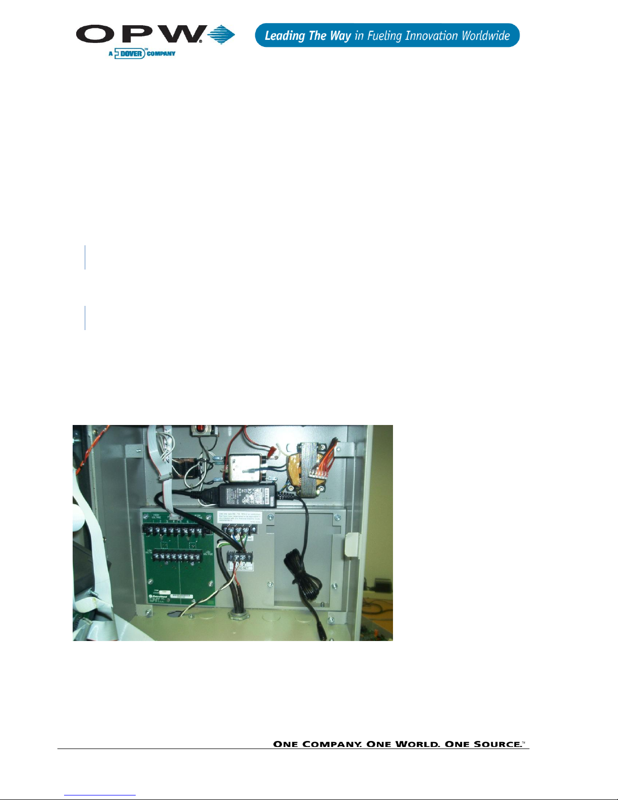
Figure 3-1 FIT-Mounted Modem Power Supply
6. Locate the power supply behind the main board.
7. Connect the power cable to the power connector on the system.
8. Connect the Petro-Net cable at this time. (Black wire to Terminal 1; White wire to Terminal 2).
Page 11

www.opwglobal.com
Document #: M00-20-7074 Rev. 005
Page 11 of 32
Figure 3-2 FIT-Mounted Modem: Inside View
9. Place the modem on the bottom of the FIT cabinet, connect the power and Petro-Net connectors.
10. Route the 1-foot antenna cable through the .375-inch hole to the .25-inch hole in the pedestal.
11. Seal the hole in the FIT with silicone.
Figure 3-3 FIT Remote Antenna: Outside View
Page 12

www.opwglobal.com
Document #: M00-20-7074 Rev. 005
Page 12 of 32
3.3 FIT with Remote Antenna (recommended)
The Wireless Petro-Net Modem® can also be set up with a remote antenna. For remote antenna mounting,
attach the directional antenna to a pole or other surface using the supplied mounting brackets. Connect the 20foot antenna cable to the modem or to the 1-foot cable in the FIT. When mounting the antenna remotely be
sure to protect the antenna cable with the appropriate conduit.
Figure 3-4 Remote Directional Antenna
3.4 Multiple FITs (Networking)
In cases where you have multiple FITs you can set up the antennas to send signals from one FIT to another.
Up to seven (7) sets of modems can operate independently in the same area.
The Networking > HP Command is used to set the modem’s hopping channel number. In order for modems
to communicate with each other, the modems must have the same channel number since each network uses a
different hopping sequence. Different channels can be used to prevent modems in one network from listening
to transmissions of another. For example, you could set system A to HP 1 and system B to HP 5. You can use
the channels between 0 and 6. The wireless modem comes is set at 0 by default.
3.5 FSC with Remote Antenna (Recommended by Manufacturer)
In areas where line-of-sight is blocked to the FSC, you can use a remote antenna. For example, the antenna
can be placed on top of the building so that it is in line-of-site with the antenna on the FIT. When determining
where to place the antenna, remember to avoid all current and possible future obstructions.
1. Attach the 20-foot antenna cable to the modem.
2. Route the cable to the remote antenna.
3. Mount the antenna to a pole or suitable surface using the hardware provided.
4. Power the modem by plugging the power supply into a wall outlet.
Page 13

www.opwglobal.com
Document #: M00-20-7074 Rev. 005
Page 13 of 32
3.6 FSC with Remote Modem
In areas where the FSC does not have a direct line-of-site with the modem and the antenna cable is too short it
is necessary to use a remote modem.
1. Extend the Petro-Net cable to position the modem where desired (1,000 feet maximum).
2. Mount the modem in a secure location (or enclosure) and attach the 20-foot antenna cable to the
modem.
3. Route the cable to the remote antenna.
4. Mount the antenna to a pole or suitable surface using the hardware provided.
5. Power the modem by plugging the power supply into a wall outlet.
3.7 FSC with Modem-Mounted Antenna (Not Recommended)
The antenna at the FSC can be mounted directly on the modem. This modem must be in the line-of-site with
the antenna at the FIT (i.e. must be near a window).
Page 14

www.opwglobal.com
Document #: M00-20-7074 Rev. 005
Page 14 of 32
3.8 Automated Tank Gauge Console
A wireless modem is connected to the VSmart Module to provide wireless communication option between the
VSmart and the SiteSentinel® iSite™. The wireless modem should ideally be placed in an area where there is
line-of-sight to the Console. Another modem is then wired to the SiteSentinel® iSite™ Console’s RS-485 port.
The Wireless option will not communicate through metal buildings.
3.8.1 SiteSentinel® iSite™ with VSmart Pole-Mounted Outside
Some installations will require an external antenna; refer to FIT with Remote Antenna on
page 15 for the VSmart and console antenna installation.
Page 15

www.opwglobal.com
Document #: M00-20-7074 Rev. 005
Page 15 of 32
3.8.2 SiteSentinel® iSite™ with VSmart in a Building
It is highly recommended that wireless Petro-Net installations are subjected to a site survey
prior to installation in order to identify potential interference problems.
Page 16

www.opwglobal.com
Document #: M00-20-7074 Rev. 005
Page 16 of 32
3.9 Communication
Petro-Net
To Modem Pin #
1 (BLACK)
8
2 (WHITE)
2
After determining the range of the modems, you can permanently install and wire the remote station modem.
Polarity is critical with all RS-485 communications. Petro-Net Terminal 1 goes to pin 8 on the modem, and
Terminal 2 goes to pin 2 on the 9-pin modem connector. Both modems are wired the same. Use the supplied
Petro-Net connector; connect the black wire to #1 on the Petro-Net Terminal and the white to the #2 Terminal.
RS-485 (Petro-Net) polarity is critical!
3.9.1 Pre-wired Petro-Net Connector
3.10 FIT Wiring
The FIT must be powered by a dedicated circuit. The FIT cannot be powered by the pump circuit or reset, as
communication problems will occur. The system warranty is void if this is not followed.
3.10.1 FIT Installation Location Wiring
1. Place the modem inside the FIT.
2. Connect the modem power pack to line voltage using the pigtail supplied.
3. Petro-Net: Use the supplied Petro-Net Connector and connect the black wire to #1 Terminal and white
to the #2 Terminal.
4. Drill a .375-inch hole for the antenna cable in the bottom of the FIT cabinet.
When drilling through the pedestal, make sure to clean up all metal chips.
5. Route the 1-foot cable from the modem to the antenna location. (Seal this hole with silicone sealant).
Be sure to maintain line-of-sight to the FSC.
6. Drill a .250-inch hole in the pedestal and attach the cable to the pedestal of the FIT and secure with
the supplied nut.
7. Attach the antenna cable.
For remote antenna mounting, attach the directional antenna to a pole or other surface using the supplied
mounting brackets. Antenna cables are available in 20-foot lengths. When mounting the antenna remotely be
sure to protect the antenna cable with conduit.
Always keep in mind where the fuel island (remote) modem is! You must maintain a line-ofsight with the remote modem for best results.
Page 17

www.opwglobal.com
Document #: M00-20-7074 Rev. 005
Page 17 of 32
3.11 FSC Installation Location Wiring
1. Place the modem on a table or shelf near the fuel site controller.
2. Plug the power pack into a wall outlet. Connect the cable from the power pack to the modem.
The indoor modem comes with a 6-inch antenna, for some applications this will work fine. When choosing a
location, keep the REMOTE modem (at the fuel island) in mind. The modems communicate better when they
are "in sight" of each other. If you experience problems, move the modem until reception is better.
3. Use the junction box cover to make the connections at the FSC. Petro-Net wire can be used to remote
either modem for best performance. Limit the wire length to 1,000 feet.
In some cases, the directional remote antenna and 20-foot cable should be used to improve communications to
the FSC when installed in metal buildings or other areas which may have poor signal strength.
Page 18

www.opwglobal.com
Document #: M00-20-7074 Rev. 005
Page 18 of 32
3.12 Tank Gauge Installation Location Wiring
The SiteSentinel® iSite™ wireless Petro-Net installation requires two wireless modems:
3.12.1 SiteSentinel® iSite™ Console Connection
1. Connect the wireless modem two-wire connector to the console Petro-Net connectors.
Black to terminal 1.
White to terminal 2.
Page 19

www.opwglobal.com
Document #: M00-20-7074 Rev. 005
Page 19 of 32
3.12.2 VSmart Connection
1. Connect the VSmart wireless modem black and white wires to the Petro-Net terminals.
Black to terminal 1.
White to terminal 2.
Page 20

www.opwglobal.com
Document #: M00-20-7074 Rev. 005
Page 20 of 32
4. XTEND Modem Advanced Configuration
This section describes how to configure modems with XTEND Advanced Configurations.
Advanced Modem Configuration is ONLY needed if you have 3 or more modems.
4.1 What You Will Need
A computer with Windows® 98, SE, 2000, or XP operating system and an available RS-232 (DB-9) serial com
port is required for XTEND Advanced Configurations.
4.2 Configuration Settings
The Wireless Petro-Net Modem®s are configured at the factory and are ready to install. You can verify the
configuration using a computer (Windows® 98, SE, 2000 or XP) and the software provided. DIP switch settings
#1, #5, #6 ON to configure and run the range test; switch settings #5, #6 ON for OPW normal operation. If the
site has communication interference, change the hopping channel on both modems to another channel.
4.3 Installing the Software
Double-click the “setup_X-CTU.exe” file and follow the prompts of the installation screens. This file is located in
the software folder of the MaxStream CD and also under the downloads section of the following Web page:
www.maxstream.net/helpdesk/
X-CTU Software—MaxStream provides software that can be used to:
Setup PC serial com ports to communicate with Wireless Petro-Net Modem®s
Test Wireless Petro-Net Modem® parameters
Configure Wireless Petro-Net Modem® parameters
1. Place the auto-running software CD in your computer’s CD drive.
2. Double-click the setup_X-CTU.exe file.
3. Follow the prompts.
The X-CTU software interface is divided into the four (4) following tabs:
PC Settings—Setup PC serial com ports to interface with the Wireless Petro-Net Modem®
Range Test—Test Wireless Petro-Net Modem®’s range under varying conditions
Terminal—Read/Set Wireless Petro-Net Modem® parameters and monitor data communications
Modem Configuration—Read/Set Wireless Petro-Net Modem® parameters
Page 21

www.opwglobal.com
Document #: M00-20-7074 Rev. 005
Page 21 of 32
4.4 FSC to Multiple FIT Operation (3 or More Wireless Modems)
If you only have two (2) wireless modems, you do not have to configure the modems and you
may proceed with the installation instructions; the modems are pre-configured for two (2) or
less modems.
If you have three (3) or more wireless modems, continue with the configuration instructions
below:
When configuring these modems with the XTC software, set DIP switches to #1, #5/#6 ON and all others OFF.
For normal operation, #5/#6 ON and all the rest OFF.
Each modem must be configured for its EXACT location.
Page 22

www.opwglobal.com
Document #: M00-20-7074 Rev. 005
Page 22 of 32
4.4.1 FSC Modem Configuration
FSC Modem
MY
10
DT
FFFF
RR 0 MT 3 HP
Must match all modems
Figure 4-1 FSC Modem Configuration
Page 23

www.opwglobal.com
Document #: M00-20-7074 Rev. 005
Page 23 of 32
4.4.2 FIT #1 Modem Configuration
FIT #1 Modem
MY
1 (FIT #)
DT
10 (FSC #)
RR A MT
0
HP
Must match all modems
Figure 4-2 FIT #1 Modem Configuration
Page 24

www.opwglobal.com
Document #: M00-20-7074 Rev. 005
Page 24 of 32
4.4.3 FIT #2 Modem Configuration
FIT #2 Modem
MY
2 (FIT #)
DT
10 (FSC #)
RR A MT 0 HP
Must match all modems
Figure 4-3 FIT #2 Modem Configuration
Page 25

www.opwglobal.com
Document #: M00-20-7074 Rev. 005
Page 25 of 32
4.5 Point-To-Point Operation (2 Wireless Modems)
When configuring these modems with the XTC software, set DIP switches to #1, #5/#6 ON and all others OFF.
For normal operation, #5/#6 ON, all the rest OFF.
It does not matter which modem is connected to the FSC or the FIT.
Page 26

www.opwglobal.com
Document #: M00-20-7074 Rev. 005
Page 26 of 32
4.5.1 Modem #1 Configuration
FIT #1 Modem
MY
1 (FIT #)
DT 2 RR
A (10)
HP
Must match all modems
Figure 4-4 Modem #1 Configuration
Page 27

www.opwglobal.com
Document #: M00-20-7074 Rev. 005
Page 27 of 32
4.5.2 Modem #2 Configuration
FIT #2
MY
2 (FIT #)
DT 1 RR
A (10)
HP
Must match all modems
Figure 4-5 Modem #2 Configuration
Page 28

www.opwglobal.com
Document #: M00-20-7074 Rev. 005
Page 28 of 32
5. Operation and Troubleshooting
This section describes how to operate and troubleshoot the Wireless Petro-Net Modem®.
Figure 5-1 DIP Switches
5.1 Hardware Setup
Wireless Petro-Net Modem®s will be referred to as “Radio 1” and “Radio 2”.
1. Set both Radio DIP switches to RS-232 mode: [Switch #1, #5, #6 up (ON) and the remaining switches
are down (OFF)].
2. Connect Radio 1 to a PC using an RS-232 cable (included with Wireless Petro-Net Modem® part
numbers that end with an “-RA” suffix).
3. Attach the serial loopback adapter (red connector) to the DB-9 serial port of Radio 2. [The serial
loopback adapter configures Radio 2 to function as a repeater by looping data back into the module for
transmission.]
4. Attach RPSMA antennas to Radio 1 and Radio 2.
5. Power Radio 1 and Radio 2 through their power connectors.
6. Use the “PC Settings” and “Range Test” tabs of the X-CTU Software to:
Assign which PC Serial Com Port to use when communicating with Wireless Petro-Net Modem®s
[Section 5.1.1: Performing a Range Test.]
Measure Wireless Petro-Net Modem®’s range [steps 1-7].
Page 29

www.opwglobal.com
Document #: M00-20-7074 Rev. 005
Page 29 of 32
5.2 Range Test Setup
Once you have completed your site survey, you must run a range test to verify the suitability of the site before
installation. The range of a wireless modem varies with its mounting location, but can be up to a mile or more.
To maximize range, survey the site. Keep the sending and receiving antennas in line-of-sight with each other.
5.2.1 Performing a Range Test
Follow the steps below to perform a range test.
1. Launch the X-CTU software. [Start > Programs > MaxStream > X-CTU]
2. Under the PC Settings tab, select the PC serial comp port from the drop-down menu that will be used
to connect to Radio 1.
3. Select the baud rate (9600) that matches the fixed RF data rate (over-the-air-baud) of Radio 1. Use
default values for the remaining fields.
4. Select the Range Test tab.
5. (Optional) Check the box in the “RSSI” section to enable its display.
6. Click the Start button to begin the range test.
7. Move Radio 2 (with loopback adapter) away from Radio 1 to measure the modem’s range.
8. After successful range test proceed to installation.
Figure 5-3 PC Settings Tab
Page 30

www.opwglobal.com
Document #: M00-20-7074 Rev. 005
Page 30 of 32
Figure 5-4 Range Test Tab
Page 31

www.opwglobal.com
Document #: M00-20-7074 Rev. 005
Page 31 of 32
5.3 Switch Settings
The XTEND-PKG-R DIP Switch allows users to configure “Serial Interface”. “Termination” and “Parity”
command parameter settings.
Figure 5-5 DIP Switch Settings (Settings applied only when powering on)
For operation, change the hopping channel to 6.
5.4 Troubleshooting
Performing a range test will give an initial indication of the expected performance. If the loopback test indicates
that additional range may be required, ask the following questions about the installation:
Do I have clear RF line-of-sight?
If the Fresnel Zone is not clear of the ground or other obstructions, often the best way to improve range is to
raise the antennas higher off the ground to help transmit over vegetation or other obstacles.
What frequency am I using?
The Wireless Petro-Net Modem® comes in two varieties: 900 MHz and 2.4 GHz. The 900 MHz waves penetrate
objects and travel better than their 2.4 GHz counterparts. If you are in the U.S., Canada, Australia or Israel, you
are using the 900-MHz radios. The 2.4-GHz radios must be used in European countries and where the ETSI
standard is required.
Can I use a directional antenna?
Directional antennas will have better gain than the omni-directional antennas. While the omni-directional-gain
antennas can improve performance in line-of-sight applications, the performance in non-line-of-sight situations
is very similar to a dipole. If you need to maximize range, using a gain antenna may be the best solution.
Page 32

www.opwglobal.com
Document #: M00-20-7074 Rev. 005
Page 32 of 32
Is the antenna mounted properly?
Using long antenna cables or having the antenna right next to metal can reduce performance. Antenna cables
add loss to a system. Using a shorter antenna cable can help keep the losses to a minimum. Often, a longer
serial data cable can be used in conjunction with a shorter coaxial cable to keep antennas in a desired location.
The radiating portion of the antenna should not touch other metal objects or be mounted right next to them.
This can cause the antenna to operate inefficiently. It is best to allow at least several inches of separation
between the antenna and other metal structures or objects.
5.4.1 OPW Switch Settings
1-watt modem (6 LEDs near connector).
Set DIP Switch #1 and #5/#6 ON, all others OFF.
Connect the supplied RS-232 cable to the modem and to the serial port on the PC.
Launch the X-CTU software and select PC settings to test the serial port, when OK (all default
settings).
Connect power to the modem and make sure power switch is up, then select modem configuration
and read. You will see the current configuration of the modem.
Under Networking, change the HP to #6.
You can now do a range test or, for a 2-modem system, set switch #5/#6 ON and all others OFF.
Ready to test with a system or to ship out.
 Loading...