

OPW Petro Vend 100, M1900 Maintenance Manual
Part Number: M1900, Rev. 8
Issue Date: 12/4/2018
Supersedes: 5/3/2017
M1900 - Petro Vend 100® Fuel Control System
Installation, Operation and Maintenance Guide
3.01.03f / 2.01m

Doc. No.: M1900 Rev.: 8
NOTE: Before you use this guide, make sure you have the latest revision. Check the revision
level of this document against the most current revision found at
http://www.opwglobal.com/opw-fms/tech-support/manuals-how-to-videos . Download the
latest revision if necessary.
OPW Fuel Management Systems is a part of Dover Fueling Solutions.
Copyright Information
Copyright © 2018 Delaware Capital Formation, Inc. All Rights Reserved. DOVER, the DOVER logo are
registered trademarks of Delaware Capital Formation, Inc., a wholly-owned subsidiary of Dover Corporation.
Page 2 of 65
Contact OPW Fuel Management Systems
Visit us at www.opwglobal.com, or contact us at:
Call 1-877-OPW-TECH (877-679-8324)
For calls outside US and Canada, call +1-708-485-4200
Monday through Friday, 7 a.m. to 6 p.m., US CST
For technician registration, see
http://opwglobal.com/TechSupport/TechnicianRegistration.aspx.
For in-depth training via OPW University, see
http://www.opwglobal.com/opw-u-training-registration.html.

Table of Contents
Doc. No.: M1900 Rev.: 8
Page 3 of 65
Section 1 Precautions
1.1 USB Flash Drives
1.2 Safety Warnings
1.3 Hazardous Areas
1.3.1 NFPA/NEC – Class I, Div. 1 & Div. 2
1.3.2 Installation Requirement
1.4 FCC Compliance
Section 2 Introduction
2.1 Terminology
2.2 Versioning
2.3 System Technical Specifications
2.3.1 Fuel Control System
2.4 Pump Control
6
6
8
9
9
10
12
13
13
13
14
14
15
2.4.1 Mechanical Pump Control
Section 3 Pre-Installation Information
3.1 Conduit/Wiring Requirements
3.1.1 Conduit Sealing
3.1.2 Pedestal Conduits
3.1.3 Grounding
3.1.4 PV100® Power Requirements
3.1.5 Pulser Wire
Section 4 System Installation
4.0.1 Typical Installation Overview
Section 5 Mechanical PCM Pump Control
15
16
16
16
17
17
18
18
19
19
22

Doc. No.: M1900 Rev.: 8
Page 4 of 65
5.1 Power Conduit Installation
5.2 PCM Conduit Installation
5.2.1 Pump Control/Pulser Conduit
5.2.2 Pump Pulser Conduit
5.3 System Power Wiring
5.4 PCM Pump Dispenser Wiring
5.4.1 Pump/Dispenser Wiring
5.4.2 Pump/Dispenser Pulser Wiring
5.5 PCM Startup/Configuration
5.5.1 Configuration (DIP Switches)
5.5.2 PCM Testing
Section 6 Complete the Installation
Section 7 System Configuration
22
23
23
23
23
24
24
26
26
26
28
30
31
7.1 Terminal Setup/Test Menu
7.1.1 Display Menu
7.1.2 Keypad Menu
7.1.3 Reader Menu
7.1.4 Tones Menu
7.1.5 System Network Number Menu
7.1.6 Petro-Net™ Setup Menu
7.1.7 Miscellaneous Menu
7.1.8 Pump Control Menu
7.1.9 Software Updates
7.2 Management Menu
7.2.1 Site Management
31
32
32
33
33
34
34
34
35
36
36
37

Doc. No.: M1900 Rev.: 8
Page 5 of 65
7.3 Pump Management
7.4 Proprietary Card File (PCF) Management
7.4.1 Clearing Totals
7.4.2 Reporting
7.5 Dual Card Security Feature
Section 8 System Maintenance
Appendix A - PV100® Primary Board
Appendix B - Termination Codes
Appendix C - Menu of Display Screens
Warranty
40
41
43
44
49
55
56
57
59
63
Section 1 Precautions
1.1 USB Flash Drives
Doc. No.: M1900 Rev.: 8
Page 6 of 65
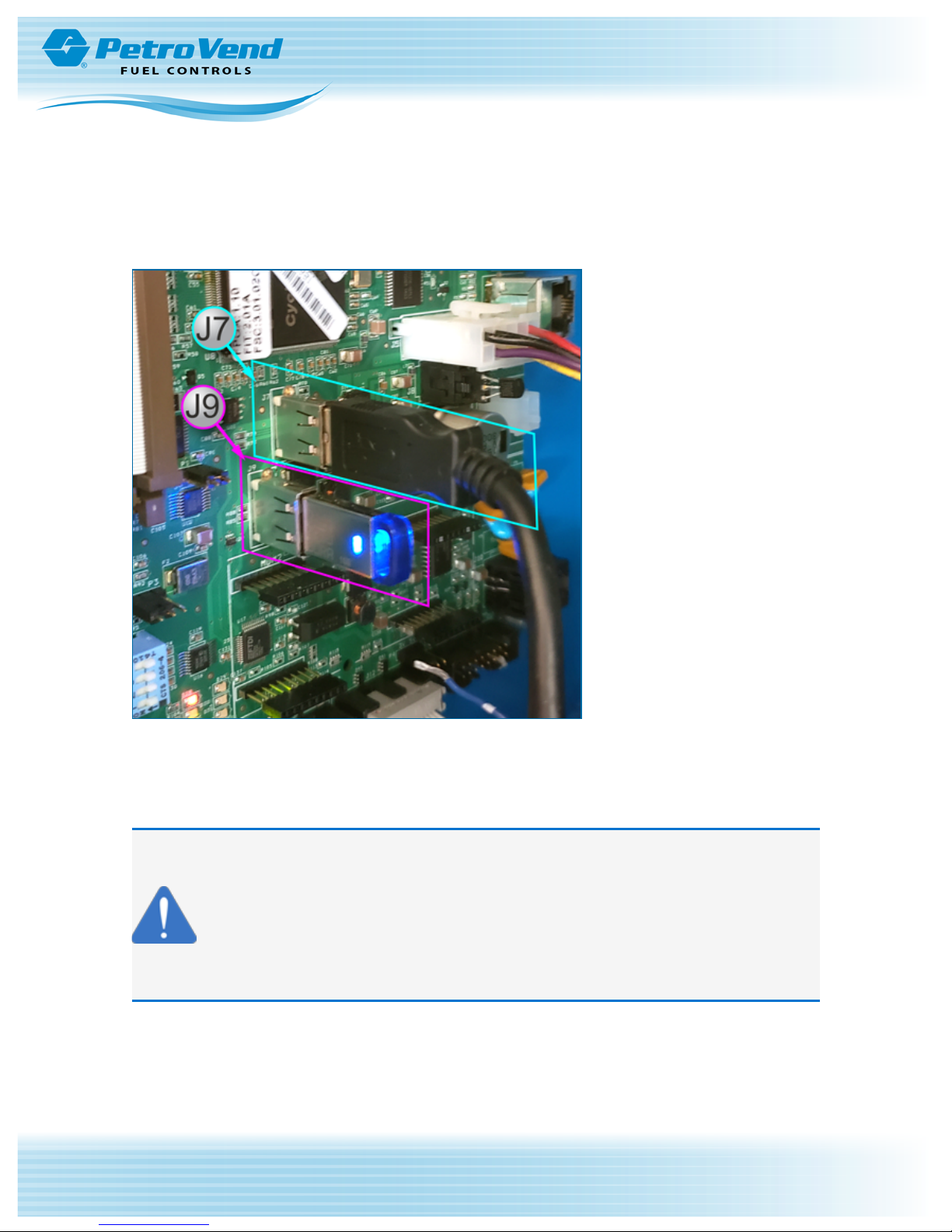
There are two (2) internal USB ports on the PV100 Main Board.
The J7 USB port (top) is used to connect the Main Board to the Door Port with the installed cable.
The J9 USB port (bottom) is for the provided metal industrial-grade USB key that is used to store data for
Totals and Transactions.
NOTICE: Use the metal industrial-grade USB Flash Drive that was provided with your unit
to store Totals and Transactions. Use this key only in the PV100 J9 USB port to prevent
loss of data.
To prevent data loss DO NOT use the plastic Manuals USB key (identified by the OPW
"diamond" logo) in the USB ports of the PV100. This key must only be used in a PC.

Doc. No.: M1900 Rev.: 8
IMPORTANT: The sub-sections that follow contain important safety and compliance
information related to the installation and operation of this unit. Read these instructions
carefully before you continue with the installation.
Page 7 of 65

Doc. No.: M1900 Rev.: 8
1.2 Safety Warnings
This manual contains many important Safety Alerts. There can be a risk of injury or damage to property if you
do not obey these alerts. The panels below show the types of safety warnings that can be seen and how
each is specified.
DANGER: Indicates an immediately hazardous condition that, if not prevented,
will result in death or serious injury.
WARNING: Indicates a possibly hazardous condition that, if not prevented,
could result in death or serious injury.
Page 8 of 65
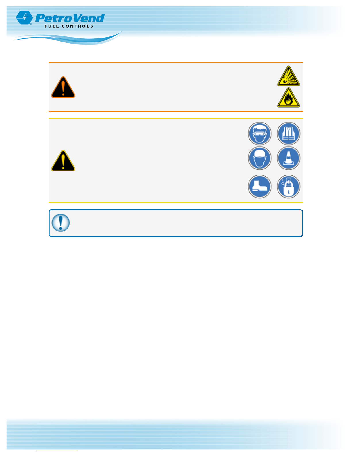
CAUTION: Indicates a possibly hazardous situation that, if not prevented,
could result in minor or moderate injury.
NOTICE: Indicates important information not related to hazards.
Doc. No.: M1900 Rev.: 8
1.3 Hazardous Areas
Any fuel dispenser is a hazardous area as defined in the National Electrical Code. Installation must be in
accordance with the following:
l National Electrical Code (NFPA No. 70)
l Motor Fuel Dispensing Facilities and Repair Garages Code (NFPA No. 30A)
1.3.1 NFPA/NEC – Class I, Div. 1 & Div. 2
The Class I, Division 1 and Class I, Division 2 hazardous areas are specified below:
Class I locations. Class I locations are those in which flammable gases or vapors are or may
be present in the air in quantities sufficient to produce explosive or ignitable mixtures. Class I
locations include the following:
1. Class I, Division 1. A Class I, Division 1 location is a location:
a. In which ignitable concentrations of flammable gases or vapors may exist under
normal operating conditions.
Page 9 of 65
b. In which ignitable concentrations of such gases or vapors may exist frequently
because of repair or maintenance operations or because of leakage.
c. In which breakdown or faulty operation of equipment or processes might release
ignitable concentrations of flammable gases or vapors, and might also cause
simultaneous failure of electric equipment.
2. Class I, Division 2. A Class I, Division 2 location is a location:
a. In which volatile flammable liquids or flammable gases are handled, processed, or
used, but in which the hazardous liquids, vapors, or gases will normally be
confined within closed containers or closed systems from which they can escape
only in case of accidental rupture or breakdown of such containers or systems, or
in case of abnormal operation of equipment; or
b. In which ignitable concentrations of gases or vapors are normally prevented by
positive mechanical ventilation, and which might become hazardous through
failure or abnormal operations of the ventilating equipment; or
c. That is adjacent to a Class I, Division 1 location, and to which ignitable
concentrations of gases or vapors might occasionally be communicated unless
such communication is prevented by adequate positive-pressure ventilation from a
source of clean air, and effective safeguards against ventilation failure are
provided.
WARNING: To prevent possible fire or explosion, do not mount your
system site controller or any other electrical part of the system, including
printers and modems, within or above the defined "hazardous" areas.

Doc. No.: M1900 Rev.: 8
IMPORTANT: It is the installer's responsibility to know and obey all local codes.
OPW Fuel Management System’s fuel control systems are listed for use in a non-classified area. All of the
equipment must be installed outside of the hazardous areas.
NOTE: Local codes can dictate specific installation requirements. Installation is subject to
approval by the local authority that has jurisdiction at the site.
1.3.2 Installation Requirement
OPW Terminals are designed to be installed above the hazardous area when using the terminal’s
associated pedestal.
The pedestal can be mounted in the hazardous area but a seal-off must be the first fitting for all conduits that
go into the area.
Page 10 of 65
IMPORTANT: All unused knockout holes that have been removed must be sealed.
Figure 1-1 Dispenser Installations
WARNING: Knockouts and installation hardware are provided for all
cabinetry. Do NOT drill holes in the enclosures. This would violate the safety
listing of the system.
CAUTION: Be sure to wear all required personal protective
equipment (PPE). This includes safety glasses, hardhat, safety
shoes and reflective vest.
Barricade the work area before installation.
Be sure to obey all applicable Lockout/Tagout (LOTO)
procedures before installation.
Doc. No.: M1900 Rev.: 8
Page 11 of 65
IMPORTANT: It is recommended to do a check of the electrical system with a multimeter to
make sure all connections are de-energized before you proceed with the installation.

Doc. No.: M1900 Rev.: 8
1.4 FCC Compliance
This system complies with Part 15 of the Federal Communications Commission (FCC) Rules & Regulations.
Operation is applicable to these conditions:
l This device must not cause harmful interference.
l This device must accept interference received, including interference that can cause undesired
operation.
Page 12 of 65

Doc. No.: M1900 Rev.: 8
Page 13 of 65
Section 2 Introduction
This installation, operation and maintenance (IOM) manual details the installation startup, testing,
configuration, and general troubleshooting instructions for the PV100®Fuel Control System by OPW Fuel
Management Systems. The PV100®system is designed with an integrated fuel-site controller to control the
system operation.
The PV100®provides a turnkey system; the only configuration required for immediate use after installation is
configuration of the network number. Upon network number configuration, all purchased cards can be
manually configured with unique PINs on the first use of the card. After configuration of the card’s PIN, a
second swipe will provide access to purchased pumps within the system.
2.1 Terminology
The abbreviations below identify terms assigned to specific components and functions within the Fuel
Control System.
l Fuel Island Terminal (FIT): Generic term used to describe the fuel management system.
l Fuel Site Controller (FSC): Hardware/firmware used to control the fueling system.
l Pump Control Module (PCM) Slave: Hardware used for controlling mechanical pumps.
l Direct Pump Control (DPC): Hardware used for communicating to electronic pumps.
2.2 Versioning
The PV100®uses two (2) separate pieces of software. One controls the Fuel Island Terminal (FIT) and
Pump Control Module (PCM), and another controls the operation of the Fuel Site Controller (FSC).
The FIT/PCM piece supplies the user interface that controls the card reader (or HID proximity reader),
keyboard and display. The interface also controls and monitors pump activity.
The FIT/PCM software uses a version number that shows three pieces of information. The number has a
format of “X.XXx.”
l The first digit identifies the number of the FIT/PCM product and stays the same for the life of the product
(the number for the PV100®is “2”).
l The next two digits after the decimal point show a major revision to the product (the starting value is
“.01”).
l The last piece is a lower case alpha character that increases when a minor modification to the
FIT/PCM occurs (the starting value is “a”).
The FSC piece of software controls the daily operations of the PV100®. This software uses a version number
that shows four pieces of information. The number has a format of “X.XX.XXx.”
l The first digit identifies the number of the FSC software and stays the same for the life of the product
(the number for the PV100®FSC is “3”).
NOTE: The FSC uses battery backed-up RAM to save the vital configuration of the FSC (e.g.,
card file setup, pump configuration, transaction data, etc.) in the event of a power failure.
l The next two digits after the decimal point show that the card file configuration has been changed. An
increase in this value shows that:
PV100®Technical Specifications
Cabinet Dimensions (H x W x D): 27 cm x 36 cm x 25 cm (10.75” x 14.25” x 9.75”
Pedestal Dimensions (H x W x D): 122 cm x 36 cm x 20 cm ( 48” x 14” x 8”)
Power Requirements: 115/230 VAC, 50/60 Hz, 200 W Max
Operating Temperature Range -40°C – +50°C (-40°F – +122°F )
Keypad Numeric/Function: Standard
Magnetic Card Reader: Optional
Proximity Card Reader: Optional
Chipkey Reader: Optional
Graphics Display: Standard 15.2 cm (6") monochrome
Enclosure: Powder Coated Steel
Pedestal: Powder Coated Aluminum
Internal Fuel Site Controller: Standard
Internal Pump Control:
Standard Mechanical - 2 hoses
Optional - Mechanical or Electronic - 4 hoses
Doc. No.: M1900 Rev.: 8
n ALL card file information such as PIN, Prompt and available pumps must be reconfigured.
n Card Pump Totals are lost.
l The next two digits show when any other system configuration has changed. The pump configuration,
stored transaction data and all saved data will be lost when this software update occurs.
Reconfiguration of this information will be necessary.
l The last piece is a lowercase alpha character that increases when a minor modification to the FSC
occurs (the starting value is “a”).
NOTE: If the card file number increases, the system configuration number can also change.
This will show that a full-system cold start will occur. A complete reconfiguration of the FSC
stored data will be necessary.
If only the system configuration number increases, a partial cold start of the FSC will occur. A
reconfiguration of pump and system control settings will be necessary.
2.3 System Technical Specifications
Page 14 of 65
This section details the technical specifications (i.e., dimensions, operating temperature range, power and
wiring requirements) of the system and pump control.
2.3.1 Fuel Control System
Mechanical Pump Control Specifications (PCM)
Relay Contact Rating: 240-volts A; 20 A, 3.0 HP Max.
“In-Use” Detection: Voltage Sense 120-240 VAC or Handle Switch
Pulser Type: Single Channel
Pulser Input: Mechanical (contact); Electronic (5-12 VDC)
Pulser Divide Rate: Pulser Divide Rate:
Max. Pulse Speed: 6,000 Mechanical; 100,000 Electronic
Doc. No.: M1900 Rev.: 8
NOTE: Optional items may require additional cost
2.4 Pump Control
2.4.1 Mechanical Pump Control
Mechanical Pump Control is used when the dispensers connected to the system provide pulse inputs
with in-use detection of handle switch or voltage sense.
Page 15 of 65
To support this type of operation, one (1) or two (2) stand-alone relay boards, referred to as the “Pump
Control Slave Module” or “PCM Slave” (OPW Part #: 20-4405), is mounted on the back wall of the PV100
enclosure, providing control for up to two (2) hoses. A second "PCM Slave" board can be added to control a
total of four (4) hoses.
®
Doc. No.: M1900 Rev.: 8
Section 3 Pre-Installation Information
The installation instructions in this manual are written for a typical installation. Due to the flexibility of the
system and the unique nature of every site, it is not possible to show every potential installation scenario.
Local codes may dictate specific installation requirements. Installation is subject to approval by jurisdictional
authorities at the site of installation. See Safety Precautions at the beginning of this manual.
Page 16 of 65
If you have a QR code scanner/reader app for your smartphone you can scan this code to view the
instructional video, PV100
tablet, simply click on the code.
®
Installation and Startup. If you are viewing this manual on a computer or
3.1 Conduit/Wiring Requirements
IMPORTANT: All wiring and conduit runs must conform to the National Electric Code (NFPA
No. 70), Code for Motor Fuel Dispensing Facilities and Repair Garages (NFPA No. 30A) and
all national, state and local codes.
All wiring running to the system must be installed in threaded, rigid metal conduit and have the
required sealoffs. AC and DC power wires can share conduit, provided they meet the PetroNet™ wiring specified; otherwise AC and DC power wires must be installed in separate
conduits.
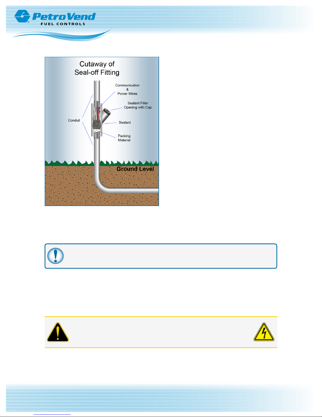
3.1.1 Conduit Sealing
Conduit entering the hazardous area must have a seal-off installed 18 inches (46 cm) above grade to prevent
liquid or fumes from entering the area.
When running shielded cable through a seal-off, strip the cable jacket back so about three (3) inches (7.6 cm)
of jacketed cable protrudes past each seal-off.
WARNING: Shielded cable is NOT vapor-tight! DO NOT damage the shield
wire! Stripped section must be in the sealed-off area.
Doc. No.: M1900 Rev.: 8
Page 17 of 65
ConduitSealing
3.1.2 Pedestal Conduits
All conduits in the PV100®pedestal should terminate at the conduit plate. A seal-off must be installed in
these conduit runs. Install ½-inch or ¾-inch rigid steel conduits as applicable.
IMPORTANT: Any unused knockout holes that have been removed must be sealed in order
to meet NEC code.
3.1.3 Grounding
ThePV100®incorporates internal noise suppression circuitry. To ensure safety and proper operation of the
equipment, all devices of the OPW system must be grounded.
A ground wire (preferably Green) must be connected between the device’s ground terminal and the main
electrical service panel. One earth ground connection is required per OPW device.
CAUTION: Do not rely on the conduit to provide ground connections.

Doc. No.: M1900 Rev.: 8
Page 18 of 65
3.1.4 PV100®Power Requirements
Power to the system must be supplied from a dedicated circuit breaker. No other equipment should be
powered from this breaker, including the pumps that are being controlled. A separate conduit from the service
panel directly to the PV100®is preferred, however, it is acceptable to share the conduit with dispenser wiring.
3.1.5 Pulser Wire
For mechanical pump installations, pulser wires must meet the pulser manufacturer’s wire requirements if
installed in separate conduit from the pump-control wires. If installed in the same conduit as the pump-control
wires, then the wire must be UL-style #2567 or equivalent. You can order shielded pulser cable from OPW
Part #: 12-1025 (two-conductor) or OPW Part #: 12-1026 (four-conductor).
Section 4 System Installation
4.0.1 Typical Installation Overview
WARNING: Install your system a minimum of 18 inches (46 cm) from the
nearest conventional or overhead pump or dispenser.
Doc. No.: M1900 Rev.: 8
Page 19 of 65
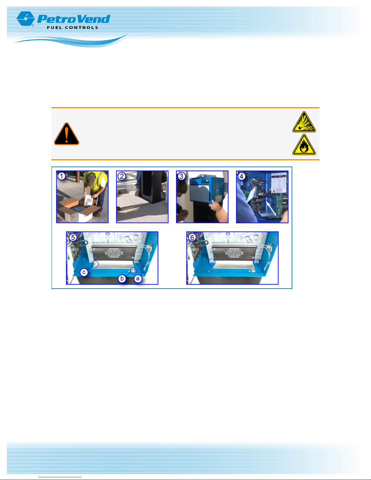
PV100®Installation
1. Unpack your new PV100®and inspect the contents for shipping damage. Make sure that all of the
following are in the box:
n A package of cards (if this will be a carded system)
n Internal USB drive
n Cabinet keys
n Noise suppressors
n Installation manual
2. Install the pedestal:
n Square the baseplate where it will be mounted
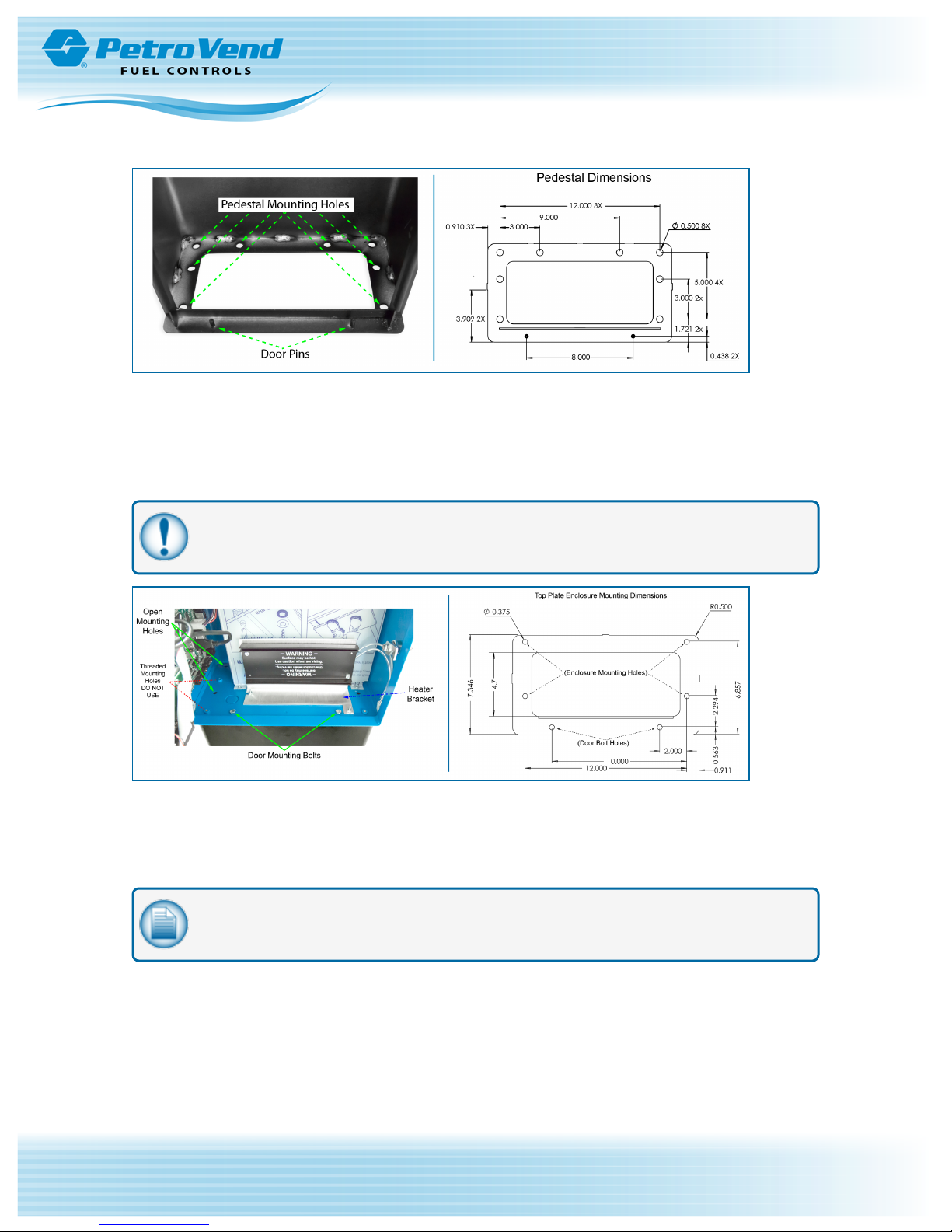
PedestalMounting Hole Locations and Dimensions
n Mark the four (4) most appropriate locations for the anchor bolts. There are eight (8) mounting
holes (see the illustrations above).
n Drill the holes
n Anchor the pedestal using 3/8” anchor bolts
Doc. No.: M1900 Rev.: 8
Page 20 of 65
IMPORTANT: Use a type of anchor bolt that is appropriate for the material in which you will
be drilling (e.g. concrete, asphalt etc.).
Enclosure Mounting to Pedestal
3. Use the provided mounting hardware to mount the PV100®enclosure to the pedestal. Align the
provided gasket with the mounting holes of the pedestal top plate. Carefully position the enclosure in
place so that the open mounting holes are aligned with the mounting holes of the pedestal. Insert the
four (4) bolts and secure them using the provided washers and nuts.
NOTE: Make sure that the open holes are being used to mount the enclosure to maintain
proper alignment of the enclosure and pedestal.
4. Disconnect the USB cable that runs from the door port to the main board.
 Loading...