

Page 1
Part Number: M00-20-7074, Rev. 6
Issue Date: 9/15/2016
Supersedes: 12/14/2011
M00-20-7074
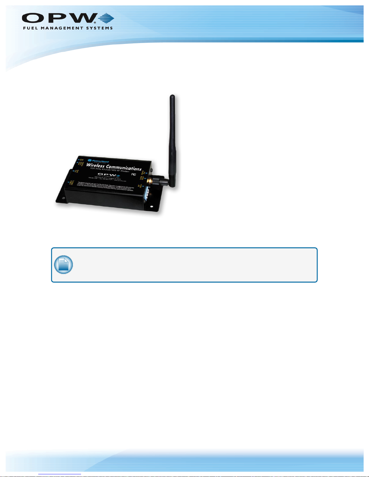
Wireless Modem
IOM
Digi-XCTU v6.3.1 and above
Page 2

Doc. No.: M00-20-7074 Rev.: 6
Copyright Information
© Copyright 2016, OPW. Printed in the USA.
© 2016 Delaware Capital Formation, Inc. All Rights Reserved. DOVER and the DOVER logo are registered
trademarks of Delaware Capital Formation, Inc., a wholly-owned subsidiary of Dover Corporation.
Contact OPW Fuel Management Systems
Visit us at www.opwglobal.com, or contact us at:
Call 1-877-OPW-TECH (877-679-8324)
For calls outside US and Canada, call +1-708-485-4200
Fax 1-800-421-3297
Monday through Friday, 7 a.m. to 6 p.m., US CST
For technician registration, see
http://opwglobal.com/TechSupport/TechnicianRegistration.aspx.
Page 2 of 43
For in-depth training via OPW University, see
http://www.opwglobal.com/opw-u-training-registration.html.
Page 3

Table of Contents
Doc. No.: M00-20-7074 Rev.: 6
Page 3 of 43
Section 1 Get Started
1.1 Overview
1.2 Wireless Modem Kit
Section 2 Installation
2.1 Pre-Installation
2.1.1 Installation Restrictions and Requirements
2.1.2 Conduct a Site Survey
2.2 Typical Installations for the Wireless Modem
2.2.1 Typical Installations
2.2.2 FIT-Mounted 6 inch Antenna
2.2.3 FIT with Remote Antenna (Recommended)
2.2.4 Multiple FITs (Networking)
2.2.5 FSC with Remote Antenna (Recommended by Manufacturer)
5
5
6
7
8
8
8
12
12
12
13
14
14
2.2.6 FSC with Remote Modem
2.2.7 FSC with Modem-Mounted Antenna (Not Recommended)
2.2.8 Automatic Tank Gauge Console
2.2.9 Communication
2.2.10 FIT Wiring
2.2.11 FSC Installation Location Wiring
2.2.12 Tank Gauge Installation Location Wiring
Section 3 XTEND Modem Advanced Configuration
3.1 What You Will Need
3.2 Installing the Software
3.3 Configuration Settings
14
14
14
16
17
17
18
19
19
19
19
Page 4

Doc. No.: M00-20-7074 Rev.: 6
Page 4 of 43
3.4 FSC to Multiple FIT Operation (3 or More Wireless Modems)
3.4.1 FSC Modem Configuration
3.4.2 FIT #1 Modem Configuration
3.4.3 FIT #2 Modem Configuration
3.5 Point-To-Point Operation (2 Wireless Modems)
3.5.1 Modem #1 Configuration
3.5.2 Modem #2 Configuration
Section 4 Operation and Troubleshooting
4.1 Hardware Setup
4.2 Range Test Setup
4.2.1 Performing a Range Test
4.3 Switch Settings
4.4 Troubleshooting
24
25
26
27
28
28
29
30
30
34
34
39
39
4.5 OPW Switch Settings
Warranty
Revision History
40
41
42
Page 5
Section 1 Get Started
Doc. No.: M00-20-7074 Rev.: 6
Page 5 of 43
Figure 1-1 Wireless Modem
These instructions show the modem hardware setup, test of the range of the radio link, advanced (optional)
configuration and suggestions for better operation.
NOTE: Some installations might not be applicable for Wireless Communications. Contact
OPW-FMS technical service for site survey and test information if you are not sure of your
installation site.
1.1 Overview
Your wireless modem can be used in many applications:
l Sites that cannot be connected by conduit, sites that contain obstructions, roads, railroad tracks, water,
etc.
l Property with restrictions on where you can dig.
l Locations with thick, reinforced concrete, such as airports, or trucking and military installations.
l Up to seven (7) wireless modems can communicate within the same network.
Page 6

1.2 Wireless Modem Kit
The Wireless Petro-Net Modem works with these systems:
l K800™ (software 1.09 or higher)
l K800
l System2™
l C/OPT
l FSC3000™
l SiteSentinel
The standard kit includes:
l Radio modems with 6 in (152.4 m) antennas
l Petro-Net
l Two (2) directional antennas
™
™
Hybrid
®
Integra™
™
connectors
Doc. No.: M00-20-7074 Rev.: 6
Page 6 of 43
l Two (2) 20 ft (6.1 m) antenna cables
Page 7

Doc. No.: M00-20-7074 Rev.: 6
Section 2 Installation
This section will give information on applicable installation procedures for different types of setups.
"Pre-Installation" on the next page will show the restrictions and requirements for wireless
communications.
"Typical Installations for the Wireless Modem" on page12 will show instructions on setup
procedures for basic installations.
Page 7 of 43
Page 8
Doc. No.: M00-20-7074 Rev.: 6
2.1 Pre-Installation
This section provides information about Wireless Petro-Net Modem requirements and restrictions for proper
installation.
2.1.1 Installation Restrictions and Requirements
NOTE:
l Some sites might NOT be suitable for Wireless Communication.
l Avoid metal buildings; the wireless modem will not communicate through metal
buildings.
l Locate the modem near a window.
l Mount the antenna on the outside of the building.
l Keep the path to the receiving modem clear. If vehicle traffic at the island blocks the
view of the receiving modem, you must reposition the antenna to maintain LINE-OFSIGHT from antenna to antenna.
Page 8 of 43
IMPORTANT: Improper operation due to poor installation planning is not covered under
warranty; it is your responsibility to verify the suitability of the wireless application.
2.1.2 Conduct a Site Survey
Before you decide to install the Wireless Modem, you must first make sure that it will work at the desired
location. Communication systems have several components that should be looked at in each system:
l Transmitting element
l Receiving device
l The environment through which communication is occurring; and
l Antennas or other focusing elements
Environment
The space between the transmitter and the receiver is the system’s environment. This will be the main focus
of your site survey. Physical obstructions and noise (interference) can enter into the environment and limit the
system’s ability to get information from one place to another.
Attaining RF Line-of-Sight (LOS) between the sending and receiving antennas is essential in achieving a
reliable signal between the FIT and the FSC. There are two types of LOS that are generally used to describe
an environment:
l Visual LOS is the ability to see from one site to the other. It requires only a straight linear path between
two points.
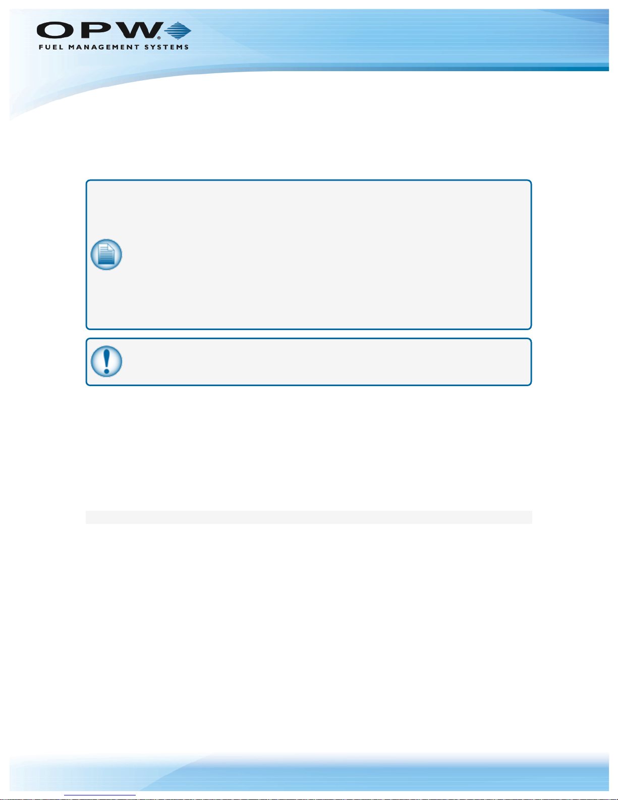
l RF LOS requires not only visual LOS, but also a football-shaped path, called a Fresnel Zone, free of
obstacles for data to optimally travel from one point to another.
Page 9
Doc. No.: M00-20-7074 Rev.: 6
Figure 2-1 Fresnel Zone
In order to achieve the greatest range, the Fresnel Zone must be free of obstructions. Buildings, trees or any
other obstacles in the path will decrease the communication range. If the antennas are mounted just barely
off the ground, more than half of the Fresnel Zone ends up being obstructed by the Earth, resulting in
significant reduction in range. To avoid this problem, the antennas should be mounted high enough off of the
ground so that the Earth does not interfere with the central diameter of the Fresnel Zone.
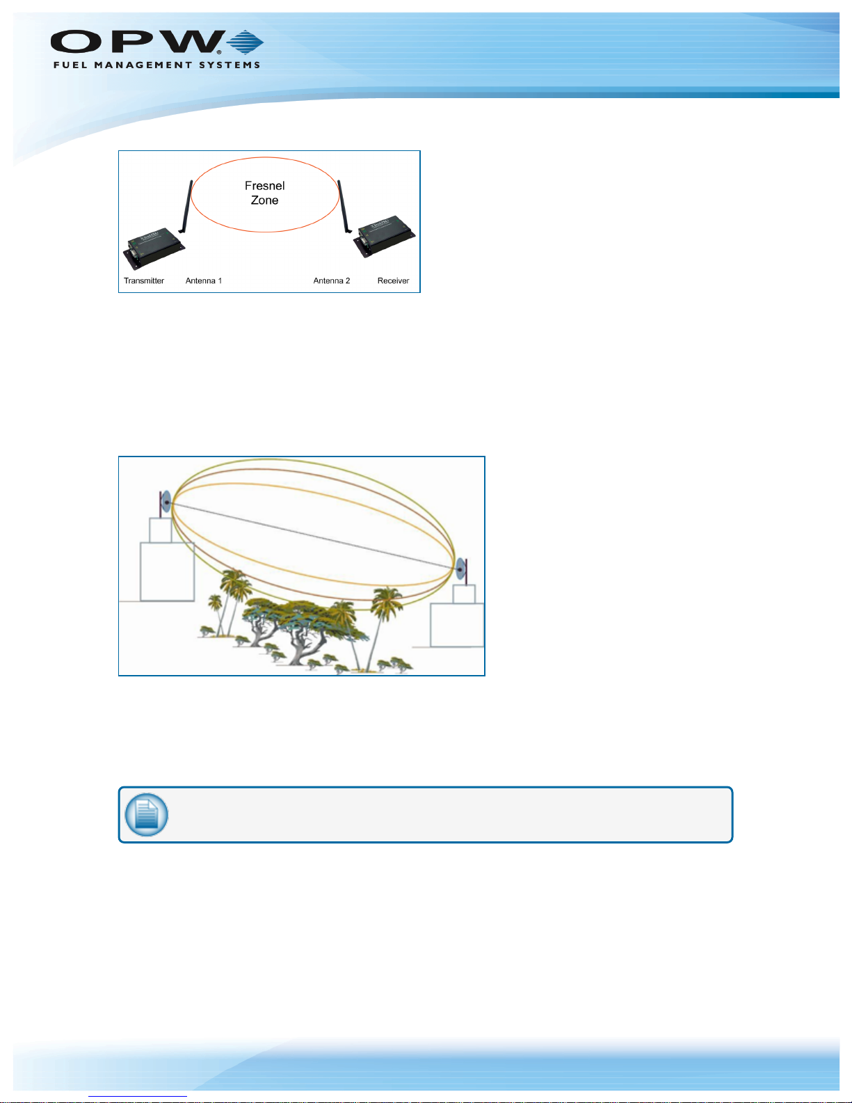
It is also important to understand that the environment may change over time due to growing vegetation,
building construction, etc. If obstacles exist between two points, the antennas can be raised on one end or on
both ends to clear the Fresnel Zone of obstructions.
Page 9 of 43
Figure 2-2 Antenna Height O ver Physical Obstructions
How far above the ground and other obstacles the antennas need to be is determined by the diameter of the
Fresnel Zone. The diameter of the Fresnel Zone depends upon the frequency and distances between the
two radios. Various data points were inserted into Fresnel Zone formulas to provide some points of
reference. The following table provides approximate Fresnel Zone diameters at 1,000 ft (304.8 m) and 1-mile
(1.6 km) ranges.
NOTE: OPW does not recommend a distance greater than 5,000 feet (1524 m).
Page 10

Fresnel Zone Diameters
Range
Distance
Required Fresnel Zone Diameter (900
MHz Radios)
Required Fresnel Zone Diameter (2.4
GHz Radios)
1000 ft. (300
m)
16 ft. (7 m) 11 ft. (5.4 m)
1 mile(1.6 km)
32 ft. (12 m) 21 ft. (8.4 m)
Doc. No.: M00-20-7074 Rev.: 6
Page 10 of 43
In order to have ground clearance, the combined antenna height should be equal to the diameter of the
Fresnel Zone.
Increased Antenna Gain
Transmitting and receiving antennas are used to focus and direct radio waves in specific directions.
Antennas are another component that can be adjusted to increase the distance data can travel in a wirelesscommunication system. Antenna gain is an important variable that can be adjusted in order to increase
range. Antenna gain describes the amount of focus the antenna is able to apply to the system by directing the
energy. The more focus the antenna can apply, the more range the system will yield. High-gain antennas can
achieve greater range than low-gain antennas, though they cover less area.
Omni-directional antennas focus energy evenly in a doughnut-shape around the antenna.
Gain vs. Vertical Beam Width (VBW)
l 2.1 dBi (0 dBd) = 75º VBW
l 5.1 dBi (3 dBd) = 33º VBW
l 8.1 dBi (6 dBd) = 17º VBW
Directional antennas focus energy more specifically in one direction.
Gain vs. Vertical Beam Width (VBW)
l 8.1 dBi (6 dBd) = 70º VBW
l 11.1 dBi (9 dBd) = 55º VBW
l 15.1 dBi (13 dBd) = 35º VBW
Page 11
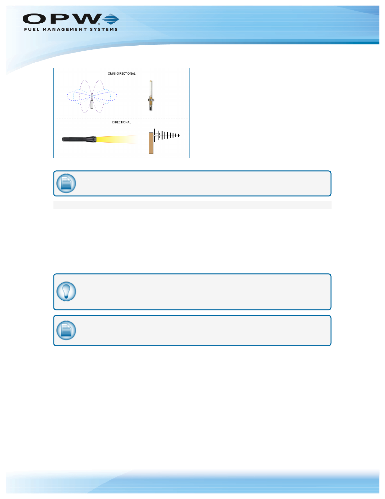
Figure 2-3 Omni-Directionaland DirectionalAntenna SignalPatterns
NOTE: Notice how, like the flashlight, the beam width is decreased as gain is increased.
Doc. No.: M00-20-7074 Rev.: 6
Page 11 of 43
Antenna Installation Considerations
When mounting an antenna, care should be taken to make sure it is as far away from metal objects as
possible. If nearby metal gets too close to an antenna, it has the potential to interfere with the way the
antenna radiates and may cause some undesirable results.
In some cases, a cable must be used to connect an antenna to a transmitter or receiver. All RF cables add
some loss to the system. For any given cable, the longer the cable the more signal will be lost over that cable.
Because of this the length of the cable should be kept as short as possible. Often a longer serial cable can be
used to minimize the length of the antenna cable.
TIP: If you have two (2) wireless modems, you do not have to configure the modems and you
can proceed with the installation instructions. The modems are pre-configured for use with one
(1) or two (2) modems.
NOTE: If you have three or more wireless modems, please refer to "FSC to Multiple FIT
Operation (3 or More Wireless Modems)" on page24 for setting up multiple modems.
Page 12
Doc. No.: M00-20-7074 Rev.: 6
2.2 Typical Installations for the Wireless Modem
This section covers the various mounting and wiring instructions for typical Wireless Petro-Net Modem®
installations.
2.2.1 Typical Installations
The Wireless Modem can be set up to work with these installations:
l
l FIT with Remote Antenna
l Multiple FITs
l FSC with Modem-Mounted Antenna
l FSC with Remote Modem
NOTE: Check with local authority for suitability of installation.
Page 12 of 43
l FSC with Remote Antenna
2.2.2 FIT-Mounted 6 inch Antenna
NOTE: The FIT-Mounted 6 inch antenna is not suitable for all applications.
When setting up the Wireless Modem, you can install the antenna directly onto the FIT.
1. Connect the power supply to the power terminals in the FIT.
2. Place the modem on the bottom of the FIT.
3. Locate and drill a .375-inch hole for the antenna cable, seal this hole with silicone sealant.
4. Locate a position on the pedestal to install the antenna, drill a .25-inch hole for the connector.
5. Remember to keep line-of-sight with the FSC antenna, (e.g. this cannot be blocked by vehicle traffic at
the island) otherwise proceed to "FIT with Remote Antenna" above.
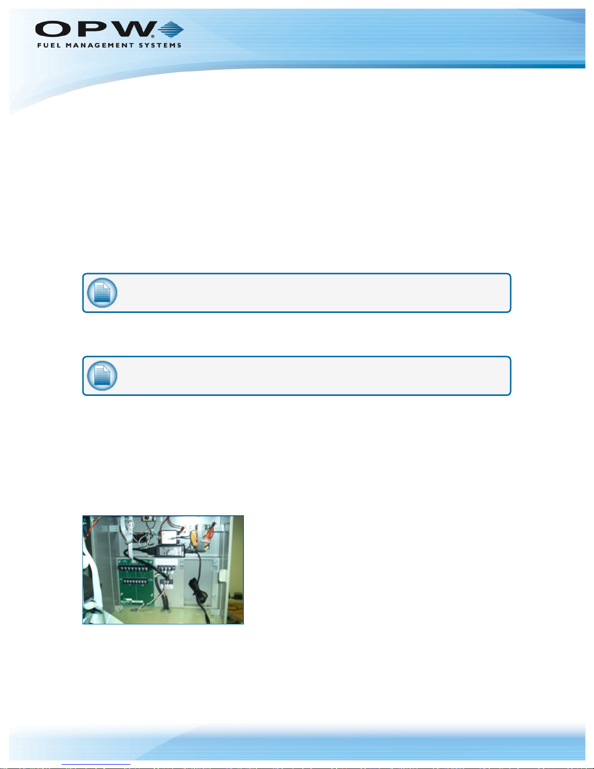
Figure 2-1 FIT-Mounted Modem Power Supply
6. Locate the power supply behind the main board.
Page 13

Doc. No.: M00-20-7074 Rev.: 6
7. Connect the power cable to the power connector on the system.
8. Connect the Petro-Net cable at this time. (Black wire to Terminal 1; White wire to Terminal 2).
Figure 2-2 FIT-Mounted Modem: Inside View
9. Place the modem on the bottom of the FIT cabinet, connect the power and Petro-Net connectors.
10. Route the 1-foot antenna cable through the .375-inch hole to the .25-inch hole in the pedestal.
11. Seal the hole in the FIT with silicone
Page 13 of 43
Figure 2-3 FIT RemoteAntenna:Outside View
2.2.3 FIT with Remote Antenna (Recommended)
The Wireless Modem can also be set up with a remote antenna. For remote antenna mounting, attach the
directional antenna to a pole or other surface using the supplied mounting brackets. Connect the 20- foot
antenna cable to the modem or to the 1-foot cable in the FIT. When mounting the antenna remotely be sure
to protect the antenna cable with the appropriate conduit.
Page 14

Doc. No.: M00-20-7074 Rev.: 6
Page 14 of 43
Figure 2-4 Remote DirectionalAntenna
2.2.4 Multiple FITs (Networking)
In cases where you have multiple FITs you can set up the antennas to send signals from one FIT to another.
Up to seven (7) sets of modems can operate independently in the same area.
The Networking > HP Command is used to set the modem’s hopping channel number. In order for
modems to communicate with each other, the modems must have the same channel number since each
network uses a different hopping sequence. Different channels can be used to prevent modems in one
network from listening to transmissions of another. For example, you could set system A to HP 1 and system
B to HP 5. You can use the channels between 0 and 6. The wireless modem comes is set at 0 by default.
2.2.5 FSC with Remote Antenna (Recommended by Manufacturer)
In areas where line-of-sight is blocked to the FSC, you can use a remote antenna. For example, the antenna
can be placed on top of the building so that it is in line-of-site with the antenna on the FIT. When determining
where to place the antenna, remember to avoid all current and possible future obstructions.
1. Attach the 20-foot antenna cable to the modem.
2. Route the cable to the remote antenna.
3. Mount the antenna to a pole or suitable surface using the hardware provided.
4. Power the modem by plugging the power supply into a wall outlet.
2.2.6 FSC with Remote Modem
In areas where the FSC does not have a direct line-of-site with the modem and the antenna cable is too short
it is necessary to use a remote modem.
1. Extend the Petro-Net cable to position the modem where desired (1,000 feet maximum).
2. Mount the modem in a secure location (or enclosure) and attach the 20-foot antenna cable to the
modem.
3. Route the cable to the remote antenna.
4. Mount the antenna to a pole or suitable surface using the hardware provided.
5. Power the modem by plugging the power supply into a wall outlet.
2.2.7 FSC with Modem-Mounted Antenna (Not Recommended)
The antenna at the FSC can be mounted directly on the modem. This modem must be in the line-of-site with
the antenna at the FIT (i.e. must be near a window).
2.2.8 Automatic Tank Gauge Console
A wireless modem is connected to the VSmart Module to provide wireless communication option between the
VSmart and the . The wireless modem should ideally be placed in an area where there is line-of-sight to the
Console. Another modem is then wired to the Integra console’s RS-485 port.
NOTE: The Wireless option will not communicate through metal buildings.
Page 15

with VSmart Pole-Mounted Outdoors
Doc. No.: M00-20-7074 Rev.: 6
Page 15 of 43
Figure 2-5 Wireless Installation with Outdoor Pole-MountedVSmart
NOTE: Some installations will require an external antenna. Refer to "FIT with Remote
Antenna" on page12 for the VSmart and console antenna installation.
Page 16

with VSmart Indoors
Petro-Net To Modem Pin #
1 (BLACK) 8
2 (WHITE) 2
Doc. No.: M00-20-7074 Rev.: 6
Page 16 of 43
Figure 2-6 Wireless Installation with VSmart Indoors
NOTE: It is recommended to fill out an Integra Site Survey (M00-2027) before doing a
wireless Petro-Net installation. This can help identify possible interference problems.
2.2.9 Communication
After determining the range of the modems, you can permanently install and wire the remote station modem.
Polarity is critical with all RS-485 communications. Petro-Net Terminal 1 goes to pin 8 on the modem, and
Terminal 2 goes to pin 2 on the 9-pin modem connector. Both modems are wired the same. Use the supplied
Petro-Net connector; connect the black wire to #1 on the Petro-Net Terminal and the white to the #2
Terminal.
IMPORTANT: RS-485 (Petro-Net) polarity is critical!
Pre-wired Petro-Net Connector
Page 17

Doc. No.: M00-20-7074 Rev.: 6
Page 17 of 43
2.2.10 FIT Wiring
The FIT must be powered by a dedicated circuit. The FIT cannot be powered by the pump circuit or reset, as
communication problems will occur. The system warranty is void if this is not followed.
FIT Installation Location Wiring
NOTE: See "Terminal Connections to Console" on the next page.
1. Place the modem inside the FIT.
2. Connect the modem power pack to line voltage using the pigtail supplied.
3. Petro-Net: Use the supplied Petro-Net Connector and connect the black wire to #1 Terminal and white
to the #2 Terminal.
4. Drill a .375-inch hole for the antenna cable in the bottom of the FIT cabinet.
REMINDER: When drilling through the pedestal, make sure to clean up all metal chips.
5. Route the 1-foot cable from the modem to the antenna location. (Seal this hole with silicone sealant).
Be sure to maintain line-of-sight to the FSC.
6. Drill a .250-inch hole in the pedestal and attach the cable to the pedestal of the FIT and secure with the
supplied nut.
7. Attach the antenna cable.
For remote antenna mounting, attach the directional antenna to a pole or other surface using the supplied
mounting brackets. Antenna cables are available in 20-foot lengths. When mounting the antenna remotely be
sure to protect the antenna cable with conduit.
IMPORTANT: Always keep in mind where the fuel island (remote) modem is! You must
maintain a line-of- sight with the remote modem for best results.
2.2.11 FSC Installation Location Wiring
1. Place the modem on a table or shelf near the fuel site controller.
2. Plug the power pack into a wall outlet. Connect the cable from the power pack to the modem.
The indoor modem comes with a 6-inch antenna, for some applications this will work fine. When choosing a
location, keep the REMOTE modem (at the fuel island) in mind. The modems communicate better when they
are "in sight" of each other. If you experience problems, move the modem until reception is better.
3. Use the junction box cover to make the connections at the FSC. Petro-Net wire can be used to remote
either modem for best performance. Limit the wire length to 1,000 feet.
In some cases, the directional remote antenna and 20-foot cable should be used to improve communications
to the FSC when installed in metal buildings or other areas which may have poor signal strength.
Page 18

2.2.12 Tank Gauge Installation Location Wiring
The wireless Petro-Net installation requires two wireless modems.
Console Connection
Figure 2-7 TerminalConnections to Console
l Connect the wireless modem two-wire connector to the console Petro-Net connectors.
Doc. No.: M00-20-7074 Rev.: 6
Page 18 of 43
n Black to terminal 1.
n White to terminal 2.
VSmart Connection
Figure 2-8 TerminalConnections to VSmart
l Connect the VSmart wireless modem black and white wires to the Petro-Net terminals.
n Black to terminal 1.
n White to terminal 2.
Page 19

Doc. No.: M00-20-7074 Rev.: 6
Section 3 XTEND Modem Advanced Configuration
This section describes how to configure modems with XTEND Advanced Configurations.
NOTE: Advanced Modem Configuration is ONLY needed if you have 3 or more modems.
3.1 What You Will Need
A computer with a Windows® operating system and an available RS-232 (DB-9) serial com port is required
for XTEND Advanced Configurations.
3.2 Installing the Software
Double-click the “setup_X-CTU.exe” file and follow the prompts of the installation screens. This file can be
downloaded from the downloads section of the following Web page:
www.digi.com/XCTU
Page 19 of 43
l X-CTU Software—Digi provides software that can be used to:
l Setup PC serial com ports to communicate with Wireless Petro-Net Modems
l Test Wireless Modem parameters
l Configure Wireless Modem parameters
1. Click the blue "DOWNLOAD XCTU" button on the Digi website (see the link above) to download the
software.
2. Double-click the setup_X-CTU.exe file.
3. Follow the prompts.
3.3 Configuration Settings
The Wireless Modems are configured at the factory and are ready to install. You can verify the
configuration using a computer and the software provided. DIP switch settings
#1, #5, #6 ON to configure and run the range test; switch settings #5, #6 ON for OPW normal operation. If the
site has communication interference, change the hopping channel on both modems to another channel.
Wireless Modems will be referred to as “Radio 1” and “Radio 2”.
4. Set both Radio DIP switches to RS-232 mode: (Switch #1, #5, #6 up [ON] and the remaining switches
are down [OFF]).
Page 20

Doc. No.: M00-20-7074 Rev.: 6
5. Connect Radio 1 to a PC using an RS-232 cable (included with Wireless Modem part numbers that
end with an “-RA” suffix)
6. Click the Discover button to find the Radio Modules connected to your PC.
Page 20 of 43
a. Select a COM Port and push Next.
Page 21

Doc. No.: M00-20-7074 Rev.: 6
Page 21 of 43
b. Select COM Parameters (use the defaults) and push Finish.
c. Wait for the modem(s) to be detected.
Page 22

Doc. No.: M00-20-7074 Rev.: 6
Page 22 of 43
7. Select the discovered modem(s).
8. Select Add selected devices.
Page 23

Doc. No.: M00-20-7074 Rev.: 6
Page 23 of 43
9. Click the Radio Module on the left to verify/configure.
Page 24

Doc. No.: M00-20-7074 Rev.: 6
Point to Point Factory Configuration
The Point to Point factory configuration settings are shown in the illustration above.
3.4 FSC to Multiple FIT Operation (3 or More Wireless Modems)
Page 24 of 43
NOTE: If you only have two (2) wireless modems, you do not have to configure the modems
and you can proceed with the installation instructions. The modems are pre-configured for use
with one (1) or two (2) modems.
If you have three (3) or more wireless modems, continue with the configuration instructions that
follow.
When you configure these modems with the XTC software, set DIP switches to #1, #5/#6 ON and all others
OFF. For normal operation, #5/#6 ON and all the rest OFF.
NOTE: Each modem must be configured for its EXACT location.
Page 25

3.4.1 FSC Modem Configuration
FSC
HP Match
MT 14
MY 0
RR 0
DT FFFF
Enter the settings in this screen as shown below.
Doc. No.: M00-20-7074 Rev.: 6
Page 25 of 43
Figure 3-1 FSC Modem Configuration
Page 26

3.4.2 FIT #1 Modem Configuration
FIT #1
HP Match
DT 0
MY 1 - XXX
RR 20
MT 14
Enter the settings in this screen as shown below.
Doc. No.: M00-20-7074 Rev.: 6
Page 26 of 43
Figure 3-2 FIT #1 Modem Configuration
Page 27

3.4.3 FIT #2 Modem Configuration
FIT #2
HP Match
DT 0
MY 2 - XXX
RR 20
MT 14
Enter the settings in this screen as shown below.
Doc. No.: M00-20-7074 Rev.: 6
Page 27 of 43
Figure 3-3 FIT #2 Modem Configuration
Page 28

Doc. No.: M00-20-7074 Rev.: 6
3.5 Point-To-Point Operation (2 Wireless Modems)
When configuring these modems with the XTC software, set DIP switches to #1, #5/#6 ON and all others
OFF. For normal operation, #5/#6 ON, all the rest OFF.
NOTE: It does not matter which modem is connected to the FSC or the FIT.
3.5.1 Modem #1 Configuration
Enter the settings as shown below.
Page 28 of 43
Figure 3-4 Modem #1 Configuration
Page 29

3.5.2 Modem #2 Configuration
Enter the settings as shown below.
Doc. No.: M00-20-7074 Rev.: 6
Page 29 of 43
Figure 3-5 Modem #2 Configuration
Page 30

Doc. No.: M00-20-7074 Rev.: 6
Section 4 Operation and Troubleshooting
This section shows how to operate and troubleshoot the Wireless Modem.
Figure 4-1 DIP-Switches
4.1 Hardware Setup
1. Set both Radio DIP switches to RS-232 mode: (Switch #1, #5, #6 up [ON] and the remaining switches
are down [OFF]).
Page 30 of 43
2. Connect Radio 1 to a PC using an RS-232 cable (included with Wireless Modem part numbers that
end with an “-RA” suffix)
3. Attach the serial loopback adapter (red connector) to the DB-9 serial port of Radio 2. [The serial
loopback adapter configures Radio 2 to function as a repeater by looping data back into the module for
transmission.]
4. Attach RPSMA antennas to Radio 1 and Radio 2.
5. Power Radio 1 and Radio 2 through their power connectors.
Figure 4-2 Range Test Cable Setup
6. Use the Discover button to find the Radio Modules connected to your PC.
Page 31

Doc. No.: M00-20-7074 Rev.: 6
Page 31 of 43
a. Select a COM Port and push Next.
b. Select COM Parameters (use the defaults) and push Finish.
Page 32

Doc. No.: M00-20-7074 Rev.: 6
Page 32 of 43
c. Wait for the modem(s) to be detected.
7. Select the discovered modem(s).
Page 33

Doc. No.: M00-20-7074 Rev.: 6
Page 33 of 43
8. Select Add selected devices.
9. Click the Radio Module on the left to verify/configure.
Page 34

Doc. No.: M00-20-7074 Rev.: 6
Page 34 of 43
4.2 Range Test Setup
Once you have completed your site survey, you must run a range test to verify the suitability of the site before
installation. The range of a wireless modem varies with its mounting location, but can be up to a mile or more.
To maximize range, survey the site. Keep the sending and receiving antennas in line-of-sight with each
other.
4.2.1 Performing a Range Test
Follow the steps below to perform a range test.
1. Launch the X-CTU software. [Start > Programs > MaxStream > X-CTU]
2. Use the Discover button to find the Radio Modules connected to your PC.
a. Select a COM Port and push Next.
Page 35

Doc. No.: M00-20-7074 Rev.: 6
Page 35 of 43
b. Select COM Parameters (use the defaults) and push Finish.
c. Wait for the modem(s) to be detected.
Page 36

Doc. No.: M00-20-7074 Rev.: 6
Page 36 of 43
3. Select the discovered modem(s).
4. Select Add selected devices.
Page 37

Doc. No.: M00-20-7074 Rev.: 6
Page 37 of 43
5. Click the Radio Module on the left to verify/configure.
Click the Tools dropdown and select Range Test.
Page 38

Doc. No.: M00-20-7074 Rev.: 6
Page 38 of 43
Under "Device Selection," select the local radio device.
a. Under "Range Test / Configuration," click the dropdown next to "Range Test type" and select
Loopback.
b. Under "Select the remote radio device," select the radio button for Specify 16-bit address.
c. Enter the source address of the other modem in the text box.
d. Click Start Range Test. The "Action Required" dialog will come into view.
Page 39

Doc. No.: M00-20-7074 Rev.: 6
Page 39 of 43
Click OK to close the dialogue window.
4.3 Switch Settings
The XTEND-PKG-R DIP Switch allows users to configure “Serial Interface”. “Termination” and “Parity”
command parameter settings.
Figure 4-3 DIP-Switch Settings (Settings applied only when powering on)
For operation, change the hopping channel to 6.
4.4 Troubleshooting
Performing a range test will give an initial indication of the expected performance. If the loopback test
indicates that additional range may be required, ask the following questions about the installation:
Do I have clear RF line-of-sight?
If the Fresnel Zone is not clear of the ground or other obstructions, often the best way to improve range is to
raise the antennas higher off the ground to help transmit over vegetation or other obstacles.
Page 40

Doc. No.: M00-20-7074 Rev.: 6
What frequency am I using?
The Wireless Modem comes in two varieties: 900 MHz and 2.4 GHz. The 900 MHz waves penetrate objects
and travel better than their 2.4 GHz counterparts. If you are in the U.S., Canada, Australia or Israel, you are
using the 900-MHz radios. The 2.4-GHz radios must be used in European countries and where the ETSI
standard is required.
Can I use a directional antenna?
Directional antennas will have better gain than the omni-directional antennas. While the omni-directionalgain antennas can improve performance in line-of-sight applications, the performance in non-line-of-sight
situations is very similar to a dipole. If you need to maximize range, using a gain antenna may be the best
solution.
Is the antenna mounted properly?
Using long antenna cables or having the antenna right next to metal can reduce performance. Antenna
cables add loss to a system. Using a shorter antenna cable can help keep the losses to a minimum. Often, a
longer serial data cable can be used in conjunction with a shorter coaxial cable to keep antennas in a
desired location. The radiating portion of the antenna should not touch other metal objects or be mounted
right next to them.
Page 40 of 43
This can cause the antenna to operate inefficiently. It is best to allow at least several inches of separation
between the antenna and other metal structures or objects.
4.5 OPW Switch Settings
l 1-watt modem (6 LEDs near connector).
l Set DIP Switch #1 and #5/#6 ON, all others OFF.
l Connect the supplied RS-232 cable to the modem and to the serial port on the PC.
l Launch the X-CTU software and select PC settings to test the serial port, when OK (all default settings).
l Connect power to the modem and make sure power switch is up, then select modem configuration and
read. You will see the current configuration of the modem.
l Under Networking, change the HP to #6.
l You can now do a range test or, for a 2-modem system, set switch #5/#6 ON and all others OFF.
l Ready to test with a system or to ship out.
Page 41

Doc. No.: M00-20-7074 Rev.: 6
Page 41 of 43
Warranty
OPW Fuel Management Systems warrants that all OPW Tank Gauge and Petro Vend Fuel Control systems supplied
by OPW Fuel Management Systems to the Original Purchaser will be free from defects in material and/or
workmanship under normal use and service for a period of 12 months from the date of installation or 15 months from
the date of shipment from OPW. Additionally, OPW Fuel Management Systems warrants that all upgrades and
replacement parts (new and remanufactured) supplied by OPW Fuel Management Systems will be free from defects in
material and workmanship under normal use and serviced for a period of 90 days from the date of installation or for the
remainder of the system’s original warranty, whichever is greater, as set forth in the first sentence of this statement.
The foregoing warranties will not extend to goods subjected to misuse, neglect, accident, or improper installation or
maintenance or which have been altered or repaired by anyone other than OPW Fuel Management Systems or its
authorized representative. The buyer’s acceptance of delivery of the goods constitutes acceptance of the foregoing
warranties and remedies, and all conditions and limitations thereof.
If a claim is made within the warranted time period that any equipment and/or remanufactured part is defective in
material or workmanship under normal use and service, such equipment and/or remanufactured part shall be returned
to OPW Fuel Management Systems, freight prepaid. If such equipment or remanufactured part is found by OPW Fuel
Management Systems in its sole judgment to be defective in material or workmanship under normal use and service,
OPW Fuel Management Systems shall, at its sole option, repair or replace such equipment and/or remanufactured part
(excluding, in all instances, fuses, ink cartridges, batteries, other consumable items, etc.) OPW Fuel Management
Systems shall not be held responsible for data loss or retrieval on returned products.
The warranties, as set forth above, are made expressly in lieu of all other warranties, either expressed or implied
(including, without limitation, warranties of merchantability and fitness for any particular purpose and of all other
obligations or liabilities on OPW Fuel Management Systems’ part.) Further, OPW Fuel Management Systems neither
assumes, nor authorizes any other person to assume for it, any other liability in connection with the sale of the
systems, or any new/replacement part that has been subject to any damage from any act of nature or any force
majeure. Any terms proposed by the Original Purchaser either orally or in writing are expressly rejected. The terms
and conditions expressed in this document may only be changed upon the express written consent of OPW Fuel
Management Systems.
The term “Original Purchaser” as used in these warranties shall be deemed to mean the authorized OPW Fuel
Management Systems’ distributor to which the system or any new/replacement part was originally sold. These
warranties may be assigned by the original purchaser to any of its customers who purchase any OPW Fuel
Management Systems’ systems or new/replacement parts. This document shall be governed by and construed in
accordance with the law of the State of Illinois. OPW Fuel Management Systems and Original Purchaser agree that
any legal action or proceeding under or with respect to this document may ONLY be brought in the courts of the State of
Illinois, or the United States District Court having jurisdiction in the City of Hodgkins, Illinois. Original Purchaser
expressly consents to personal jurisdiction in any of the above-mentioned forums and agrees to waive all defenses
based on improper venue or inconvenient form should an action be brought therein.
The sole liability of OPW Fuel Management Systems, for any breach of warranty, shall be as set forth above. OPW
Fuel Management Systems does not warrant against damage caused by accident, abuse, faulty or improper
installation or operation. In no event shall manufacturer’s liability on any claim for damages arising out of the
manufacture, sale, delivery or use of the goods exceed the original purchase price of the goods. In no event shall OPW
Fuel Management Systems be liable for any direct, indirect, incidental or consequential damage or loss of product.
TERMS
Ex-works our factory, Hodgkins, Illinois, USA
Installation not included.
All trade names are registered. Patents pending.
Subject to engineering improvement and/or other changes.
Page 42

Revision History
Revision ECO # Effective
Software
Version
Key Changes
0 NA NA
1 NA NA
2 NA NA
3 127 4/1/11
4 150 4/20/11
5 348 4/11/12 Rebrand
6 1050
Digi - XCTU
version
6.3.1
Significant changes to GUI from manufacturer.
Reactivated original p/n.
9/15/16
Doc. No.: M00-20-7074 Rev.: 6
Page 42 of 43
Page 43

 Loading...