

Page 1

Part Number: M00-20-6020, Rev. 1
Issue Date: February 27, 2017
Supersedes: March 5, 2016
M00-20-6020
Ethernet Radio
User's Guide
Page 2

Doc. No.: M00-20-6020 Rev.: 1
Copyright Information
© Copyright 2016, OPW. Printed in the USA.
© 2016 Delaware Capital Formation, Inc. All Rights Reserved. DOVER and the DOVER logo are registered
trademarks of Delaware Capital Formation, Inc., a wholly-owned subsidiary of Dover Corporation.
Contact OPW Fuel Management Systems
Visit us at www.opwglobal.com, or contact us at:
Call 1-877-OPW-TECH (877-679-8324)
For calls outside US and Canada, call +1-708-485-4200
Fax 1-800-421-3297
Monday through Friday, 7 a.m. to 6 p.m., US CST
For technician registration, see
http://opwglobal.com/TechSupport/TechnicianRegistration.aspx.
Page 2 of 22
For in-depth training via OPW University, see
http://www.opwglobal.com/opw-u-training-registration.html.
Page 3

Compliance Statement
Doc. No.: M00-20-6020 Rev.: 1
Page 3 of 22
Page 4

Table of Contents
Doc. No.: M00-20-6020 Rev.: 1
Page 4 of 22
Section 1 Operational Summary
1.1 General Information
Section 2 Components
Section 3 Installation
3.1 Antenna Alignment and Orientation Guide
3.2 Install the Access Point
3.2.1 External Version
3.2.2 Internal Version
3.3 Test the System
Section 4 Abbreviation Guide
Appendix A - Pair the 20-6020-EXT
Appendix B - Pair the 20-6020-INT
Warranty
5
6
7
9
10
11
11
11
13
14
15
18
20
Page 5

Doc. No.: M00-20-6020 Rev.: 1
Section 1 Operational Summary
Use the 20-6020 Radio to set up a long-range, wireless Ethernet network. The 20-6020 is made up of a preconfigured radio pair.
The access point (AP) automatically scans for the best of the 12 available radio frequency channels, encrypts
Ethernet data received from the network, and transmits it wirelessly to the correct subscriber unit (SU). The
AP is constantly monitoring the radio link and can automatically change the channel if performance is
degraded due to interference. If two AP units are very close to one another, they may interfere if operating on
adjacent frequency channels. Place them at least 10 feet apart and manually select non-adjacent channels
for their operation. Also, the SU should be placed at least 10 feet from the AP to avoid overloading the radio’s
receiver.
Page 5 of 22
Page 6

Doc. No.: M00-20-6020 Rev.: 1
1.1 General Information
The 20-6020 Ethernet Radio pairs are designed to supply a wireless Ethernet connection to the fuel island.
They work up to 40 miles with line-of-site and directional antennas. They will also work non-line-of-site over
shorter distances. Built-in link quality LEDs show the strength of the signal.
Units are setup as a matched pair. 128 bit data encryption ensures the data is secure.
The -EXT version comes with one weatherproof Access Point and one weatherproof Subscriber Unit. The
Access Point is typically installed on a building where the Ethernet connection is located. The Subscriber
Unit is typically installed on a pole at the fuel island where Ethernet access is needed. Each radio is powered
by a wall pack using a PoE injector. Each comes with a mounting bracket and an omni-directional whip
antenna (an optional directional Yagi antenna is also available).
The –INT version comes with one weatherproof Access Point and one board-level Subscriber Unit. The
Access Point is typically installed on a building where the Ethernet connection is located. It is powered by a
wall pack using a PoE injector. It comes with a bracket and an omni-directional whip antenna. (an optional
directional Yagi antenna is also available). The Subscriber Unit is mounted on the FSC3000 circuit board.
The FSC3000 is installed inside the Fuel Island Terminal. A weatherproof omni-directional panel mount
antenna is installed in the top of the Fuel Island Terminal enclosure.
Page 6 of 22
Page 7
20-6020-EXT
Qty. Component
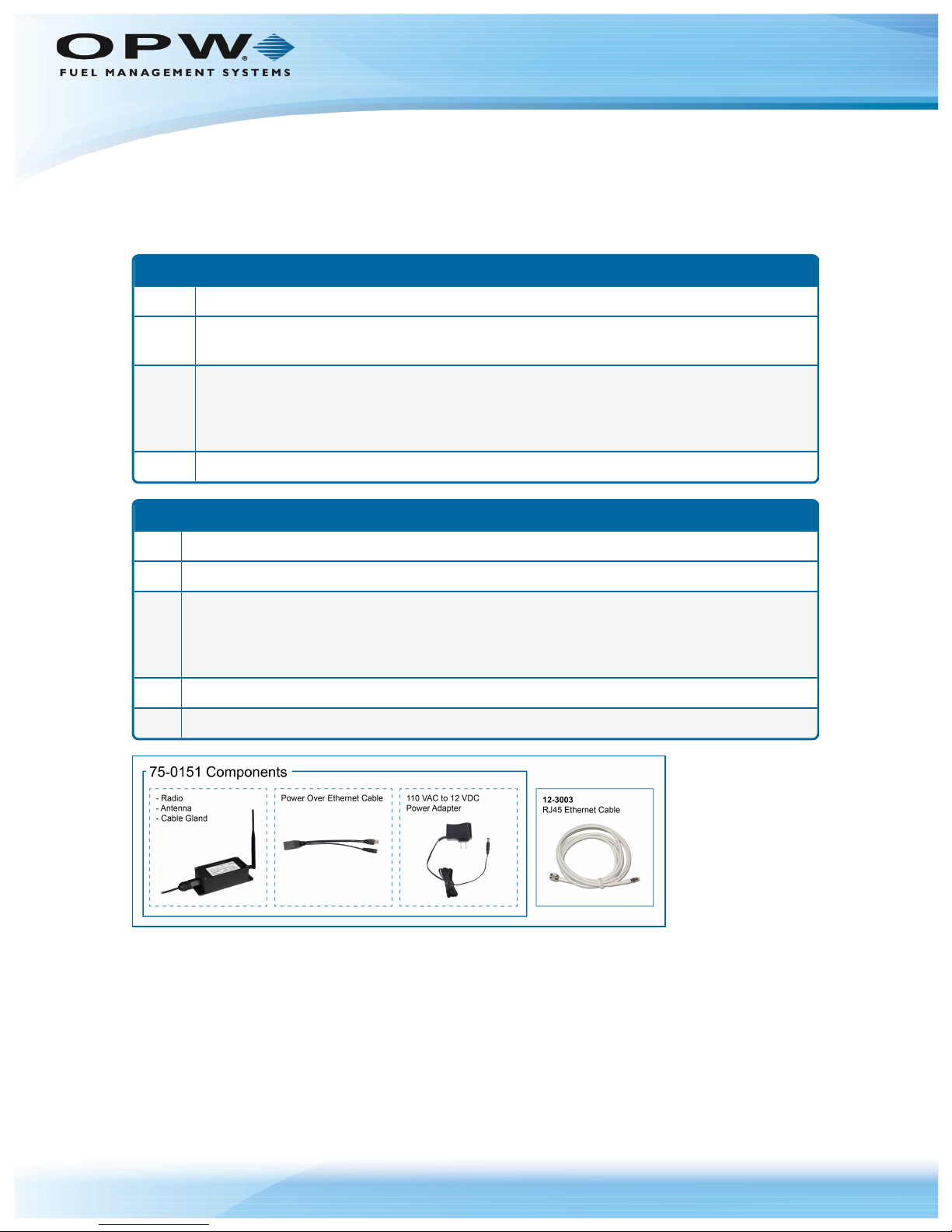
2
75-0151 radio in extruded aluminum box (one [1] Access Point and one [1] Subscriber Unit paired).
Included with 75-0151:
Two (2) AW2-900 2.5dBi omnidirectional antenna
Two (2) AW-PoE Power Over Ethernet injectors
Two (2) 110 VAC to 12 VDC power adapters
2 12-3003 25' Ethernet Cable
20-6020-INT
Qty. Component
1 75-0151-M radio in extruded aluminum box (Access Point)
Included with 75-0151:
One (1) AW2-900 2.5dBi omnidirectional antenna
One (1) AW-PoE Power Over Ethernet injector
One (1) 110 VAC to 12 VDC power adapter
1 12-3003 25' Ethernet Cable
1 20-6021 Radio Assembly (installed on internal w/terminal mounted antenna
Doc. No.: M00-20-6020 Rev.: 1
Section 2 Components
Please check your product packaging and make sure all components are included and not damaged.
Page 7 of 22
Figure 2-1 75-0151 Components
Page 8

Doc. No.: M00-20-6020 Rev.: 1
Figure 2-2 75-2010 DirectionalAntenna Option
20-6021 Radio Assembly
The 20-6020-INT includes the 20-6021 Subscriber Unit that comes pre-installed with the internal FSC3000
of your purchased Fuel Island Terminal. The parts of this Subscriber Unit are shown below.
Page 8 of 22
Figure 2-3 20-6021 Subscriber Unit
Page 9

Section 3 Installation
This section outlines the details for component installation.
l Antenna Alignment and Orientation
l Mount the Access Point
l System Test
NOTE: The Access Point and Subscriber units included in both, 20-6020-EXT and 20-6020-
INT have been paired at the factory. If it ever becomes necessary to pair the units because of
lost communication (they have lost their pairing) or for a replacement unit, see Appendix A (for
20-6020-EXT) or Appendix B (for 20-6020-INT) for procedures on how to correctly pair the
units.
Doc. No.: M00-20-6020 Rev.: 1
Page 9 of 22
Page 10

Doc. No.: M00-20-6020 Rev.: 1
3.1 Antenna Alignment and Orientation Guide
When you install the antennae, be sure the pairs are aligned and oriented correctly. Use the guide below:
Page 10 of 22
Figure 3-1 AntennaAlignment
Page 11

Doc. No.: M00-20-6020 Rev.: 1
3.2 Install the Access Point
1. Attach the Access Point to the building or pole.
2. Remove the weatherproof cable gland, push the 12-3003 RJ45 cable through the cable gland,
connect the RJ45 cable to the Access Point and screw the cable gland back into the housing.
3. Route the other end of the 12-3003 RJ45 cable into the building and plug it into the Power over
Ethernet (PoE) cable.
4. Plug the PoE cable into the RJ45 Ethernet connection that exists in the building.
5. Plug the power pack into a receptacle and plug the power connector into the PoE cable.
3.2.1 External Version
Install the Subscriber Unit
1. Attach the Access Point to the building or pole.
2. Remove the weatherproof cable gland, push the 12-3003 RJ45 cable through the cable gland,
connect the RJ45 cable to the Access Point and screw the cable gland back into the housing.
Page 11 of 22
3. Route the other end of the 12-3003 RJ45 cable into the terminal (or wherever the device's Ethernet
connection is located), and plug it into the PoE cable.
4. Plug the PoE cable into the device's RJ45 Ethernet connector.
5. Plug the power pack into a receptacle and plug the power connector into the PoE cable.
3.2.2 Internal Version
l If you have the –INT version, use the M1700 FSC3000 Installation, Operation and Maintenance
Guide to install the Fuel Control system. The Subscriber unit is pre-installed on the FSC3000 board so
there will be no other steps necessary. To access the M1700 IOM scan or click the QR code below or
go to http://www.opwglobal.com/docs/libraries/manuals/electronic-systems/opw-fms-
manuals/M1700-FSC3000-Installation-Configuration-Manual.pdf?sfvrsn=12
Page 12

Doc. No.: M00-20-6020 Rev.: 1
Page 12 of 22
Figure 3-1 Access Point Cable Connections
Page 13

Doc. No.: M00-20-6020 Rev.: 1
IMPORTANT: The POE cable only supplies power to the female connector. DO NOT plug
the integrated RJ45 end of the POE cable into the Ethernet modem or it will not be powered!
Page 13 of 22
Figure 3-2 Incorrect Cable Connection
3.3 Test the System
The Wireless Ethernet Radios are preconfigured and paired to communicate with each other. When power is
applied, the channel LEDs will search for the clearest channel and lock in on one. This indicates that the two
units are communicating. The 6 link quality LEDs will indicate the relative strength of the signal.
Page 14

Section 4 Abbreviation Guide
AP: Access Point
CH: Channel
DHCP: Dynamic Host Configuration Protocol
ECD: Ethernet Client Device
IP: Internet Protocol
LCD: Liquid-Crystal Display
RF: Radio Frequency
RP: Reversed Polarity
RX: Receive
SU: Subscriber Unit
Doc. No.: M00-20-6020 Rev.: 1
Page 14 of 22
TNC: Need name of plug
TX: Transmit
Page 15

Doc. No.: M00-20-6020 Rev.: 1
Appendix A - Pair the 20-6020-EXT
Work Instructions to configure and pair the 20-6020-EXT Ethernet Radio Modems
NOTE: The Access Point and Subscriber units included in the 20-6020-EXT have been
paired at the factory. If it ever becomes necessary to pair the units because of lost
communication (they have lost their pairing) or for a replacement unit, use the procedure
below on how to correctly pair the units.
IMPORTANT: Do not apply power to either the Access Point or the Subscriber unit until
instructed to do so. Refer to the instructions below.
1. Refer to the image "Pair the 20-6020-EXT Modems" on page17 for connections and the steps shown
below.
Page 15 of 22
2. Use a 3mm Allen wrench (not supplied) to remove the cover from one of the units. This unit will be
specified as the Access Point.
3. Make sure the Access Point and the Subscriber Unit are set at least 10 feet apart.
4. Attach the antennas to both units.
5. Connect a 12-3003 Ethernet cable from each radio modem to the female connector of its PoE cable.
NOTE: To correctly pair the two (2) Ethernet radio units of the 20-6020-EXT, it will be
necessary to have an RJ45 coupler. This is NOT a supplied component.
6. Use an RJ45 coupler (NOT supplied) to connect the RJ45 ends of both PoE cables together.
7. Connect the two power supply cords to their PoE cables. Do not plug the power supplies into power
outlets at this time.
8. Turn switch "1" of the specified Access Point unit to the ON position (Switch 1 is toward the side of the
board of the antenna coaxial connector).
9. Plug in the power supplies of both units to power outlets to turn the units on.
10. The link quality LEDs on both units will sequence up and down for 5 seconds (The LEDs of the
Subscriber Unit can be seen through the LED view window on the cover of the unit).
Page 16

Doc. No.: M00-20-6020 Rev.: 1
11. If the units have been correctly paired and their encryption keys loaded, the condition of the link
quality LEDs of both units should be as follows:
a. The first green link quality LED on the Subscriber Unit will flash.
b. The link quality LEDs on the Access Point continue to sequence up and down.
12. Unplug the power supplies of both units to turn them off.
13. Disconnect the RJ45 connector ends of both PoE cables from the RJ45 coupler.
14. Plug in the power supplies of both units to power outlets to turn the units back on.
15. The link quality LEDs on both units will sequence up and down for 5 seconds
16. The channel LEDs on both units will search and then lock-in on the clearest channel. If this does not
occur, the units have not been correctly paired.
NOTE: If pairing does not occur, redo the procedure from step 6.
Page 16 of 22
17. The link quality LEDs will then light to show the signal strength.
18. Put the cover back on the Access Point.
Page 17

Doc. No.: M00-20-6020 Rev.: 1
Page 17 of 22
Figure A-1 Pair the 20-6020-EXT Modems
Page 18

Doc. No.: M00-20-6020 Rev.: 1
Appendix B - Pair the 20-6020-INT
Work Instructions to configure and pair the 20-6020-INT Ethernet Radio Modems
NOTE: The Access Point and Subscriber units included in the 20-6020-INT have been paired
at the factory. If it ever becomes necessary to pair the units because of lost communication
(they have lost their pairing) or for a replacement unit, use the procedure below on how to
correctly pair the units.
IMPORTANT: Do not apply power to either the Access Point or the FSC3000 until instructed
to do so. Refer to the instructions below.
1. Refer to the image "Pair the 20-6020-INT Modems" on the next page for connections and the steps
shown below.
Page 18 of 22
2. Use a 3mm Allen wrench (not supplied) to remove the cover from the Access Point.
3. Make sure the two units are set at least 10 feet apart.
4. Attach the antenna to the Access Point.
5. Connect the 12-3003 Ethernet cable from the Access Point to the PoE cable.
6. On the Subscriber Unit, temporarily disconnect the short Ethernet connection coming from the
FSC3000.
7. Plug the PoE cable into the Ethernet port of the Subscriber Unit on the FSC3000 board.
8. Connect the power supply cord to the PoE cable. Do not plug the power supply into power at this
time.
9. Turn switch "1" of the Access Point unit to the ON position (Switch 1 is toward the side of the board of
the antenna coaxial connector).
10. Plug in the power supply of the Access Point and plug in the FSC3000 power cord to turn them both
on.
11. The link quality LEDs on both units will sequence up and down for 5 seconds
12. If the units have been correctly paired and their encryption keys loaded, the condition of the link
quality LEDs of both units should be as follows:
a. The first green link quality LED on the Subscriber Unit will flash.
b. The link quality LEDs on the Access Point continue to sequence up and down.
13. Unplug the Access Point power supply and the FSC3000 power cord.
14. Disconnect the RJ45 connector end of the PoE cable from the Ethernet port of the Subscriber unit.
15. Reconnect the short Ethernet cable of the FSC3000 to the Ethernet port of the Subscriber Unit.
Page 19

Doc. No.: M00-20-6020 Rev.: 1
Page 19 of 22
16. Plug in the power supply of the Access Point and the FSC3000 power cord to power outlets to turn the
units back on.
17. The link quality LEDs on both units will sequence up and down for 5 seconds.
18. The channel LEDs on both units will search and then lock-in on the clearest channel. If this does not
occur, the units have not been correctly paired.
NOTE: If pairing does not occur, redo the procedure from step 6.
19. The link quality LEDs will then light to show the signal strength.
20. Put the cover back on the Access Point.
Figure B-1 Pair the 20-6020-INT Modems
Page 20

Doc. No.: M00-20-6020 Rev.: 1
Page 20 of 22
Warranty
OPW Fuel Management Systems warrants that all OPW Tank Gauge and Petro Vend Fuel Control systems supplied
by OPW Fuel Management Systems to the Original Purchaser will be free from defects in material and/or
workmanship under normal use and service for a period of 12 months from the date of installation or 15 months from
the date of shipment from OPW. Additionally, OPW Fuel Management Systems warrants that all upgrades and
replacement parts (new and remanufactured) supplied by OPW Fuel Management Systems will be free from defects in
material and workmanship under normal use and serviced for a period of 90 days from the date of installation or for the
remainder of the system’s original warranty, whichever is greater, as set forth in the first sentence of this statement.
The foregoing warranties will not extend to goods subjected to misuse, neglect, accident, or improper installation or
maintenance or which have been altered or repaired by anyone other than OPW Fuel Management Systems or its
authorized representative. The buyer’s acceptance of delivery of the goods constitutes acceptance of the foregoing
warranties and remedies, and all conditions and limitations thereof.
If a claim is made within the warranted time period that any equipment and/or remanufactured part is defective in
material or workmanship under normal use and service, such equipment and/or remanufactured part shall be returned
to OPW Fuel Management Systems, freight prepaid. If such equipment or remanufactured part is found by OPW Fuel
Management Systems in its sole judgment to be defective in material or workmanship under normal use and service,
OPW Fuel Management Systems shall, at its sole option, repair or replace such equipment and/or remanufactured part
(excluding, in all instances, fuses, ink cartridges, batteries, other consumable items, etc.) OPW Fuel Management
Systems shall not be held responsible for data loss or retrieval on returned products.
The warranties, as set forth above, are made expressly in lieu of all other warranties, either expressed or implied
(including, without limitation, warranties of merchantability and fitness for any particular purpose and of all other
obligations or liabilities on OPW Fuel Management Systems’ part.) Further, OPW Fuel Management Systems neither
assumes, nor authorizes any other person to assume for it, any other liability in connection with the sale of the
systems, or any new/replacement part that has been subject to any damage from any act of nature or any force
majeure. Any terms proposed by the Original Purchaser either orally or in writing are expressly rejected. The terms
and conditions expressed in this document may only be changed upon the express written consent of OPW Fuel
Management Systems.
The term “Original Purchaser” as used in these warranties shall be deemed to mean the authorized OPW Fuel
Management Systems’ distributor to which the system or any new/replacement part was originally sold. These
warranties may be assigned by the original purchaser to any of its customers who purchase any OPW Fuel
Management Systems’ systems or new/replacement parts. This document shall be governed by and construed in
accordance with the law of the State of Illinois. OPW Fuel Management Systems and Original Purchaser agree that
any legal action or proceeding under or with respect to this document may ONLY be brought in the courts of the State of
Illinois, or the United States District Court having jurisdiction in the City of Hodgkins, Illinois. Original Purchaser
expressly consents to personal jurisdiction in any of the above-mentioned forums and agrees to waive all defenses
based on improper venue or inconvenient form should an action be brought therein.
The sole liability of OPW Fuel Management Systems, for any breach of warranty, shall be as set forth above. OPW
Fuel Management Systems does not warrant against damage caused by accident, abuse, faulty or improper
installation or operation. In no event shall manufacturer’s liability on any claim for damages arising out of the
manufacture, sale, delivery or use of the goods exceed the original purchase price of the goods. In no event shall OPW
Fuel Management Systems be liable for any direct, indirect, incidental or consequential damage or loss of product.
TERMS
Ex-works our factory, Hodgkins, Illinois, USA
Installation not included.
All trade names are registered. Patents pending.
Subject to engineering improvement and/or other changes.
Page 21

Revisions
Revision # ECO Effective Software Version Key Changes
0 919 3/9/16 na Initial Release
1 1128
na
Added installation and pairing
instructions for Internal and
External versions
Doc. No.: M00-20-6020 Rev.: 1
Page 21 of 22
2/27/17
NOTE: It is possible that older software versions might not support all features
Page 22

 Loading...