

Page 1

71SO Overfill Prevention Valves and
71SO Testable Overfill Prevention Valves
Installation and Maintenance Instructions
IMPORTANT INFORMATION
FOLLOW ALL INSTRUCTIONS
Please read these warnings and use and assembly
instructions completely and carefully before starting. Failure to do so may cause product failure, or
result in environmental contamination due to liquid
leakage into the soil, creating hazardous spill conditions.
OPW Standard Product Warranty Tag: Notice: FlexWorks by OPW, Inc., VAPORSAVER™ and all other OPW
products must be used in compliance with all applicable federal, state, provincial and local laws, rules and
regulations. Product selection is the sole responsibility
of the customer and/or its agents and must be based
on physical specications and limitations, compatibility with the environment and material to be handled.
All illustrations and specications in this literature are
based on the latest production information available
at the time of publication. Prices, materials and specications are subject to change at any time, and models may be discontinued at any time, in either case,
without notice or obligation.
OPW warrants solely to its customer (the initial purchaser and any subsequent purchasers within the
warranty period) that the following products sold by
OPW will be free from defects in materials and workmanship under normal use and conditions for the periods indicated:
PRODUCT WARRANTY PERIOD
FlexWorks Primary Pipe 10 years from date of manufacture
All Products and replacement parts in-
stalled in the State of
California
Certied to California CP
-201 and/or CP-206
Standards*
All other Products and
replacement parts
*Products certied to California CP-201 and/or CP-206 Standards
have been factory tested and met all applicable performance stand-
ards and specications and will have an OPW registration card en-
closed/attached to the product.
1 year from date of installation (proof of
purchase from certied contractors/
technicians required)
OPW warrants ongoing compliance with
the standards and specications for the
duration of the warranty period required
by the State of California; this limited war-
ranty is under the condition the equip-
ment was installed and maintained by
trained and certied contractors/
technicians unless noted in Installation
Manual.
1 year from date of manufacture**
OPW’s exclusive obligation under this limited warranty is, at its option, to repair, replace or issue credit (in
an amount not to exceed the list price for the product)
for future orders for any product that may prove defective within the applicable warranty period. (Parts
repaired or replaced under warranty are subject to
prorated warranty coverage for remainder of the original warranty period). Complete and proper warranty
claim documentation and proof of purchase required.
All warranty claims must be made in writing and delivered during the applicable warranty period to OPW at
OPW 9393 Princeton-Glendale Road Hamilton, Ohio,
USA 45011, Attention: Customer Service Manager. No
products may be returned to OPW without its prior
written authority.
This limited warranty shall not apply to any FlexWorks
or VAPORSAVER™ product unless it is installed by an
OPW attested installer and all required site and warranty registration forms are completed and received by
OPW within 60 days of installation. This limited warranty also shall not apply to any FlexWorks, VAPORSAVER™
or other OPW product: unless all piping connections are
installed with a nationally-recognized or stateapproved leak detection device in each tank and dispenser sump (which are not for storage and from which
all discharge hydrocarbons must be removed, and the
systems completely cleaned, within 24 hours); unless
testable sumps utilize FlexWorks pipe and access ttings; unless a sump inspection log or an EPA recommended/required checklist is maintained and the results are furnished to OPW upon request; and unless
OPW is notied within 24 hours of any known or suspected product failure and is provided with unrestricted access to the product and the site. This limited warranty also shall not apply to any product which has
been altered in any way, which has been repaired by
anyone other than a service representative authorized
by OPW, or when failure or defect is due to: improper
installation or maintenance (including, without limitation, failure to follow FlexWorks Quick Reference Manual Installation Guide and all product warning labels);
abuse or misuse; violation of health or safety requirements; use of another manufacturer’s, or otherwise un-
1
Page 2

authorized, substances or components; soil or other
surface or subsurface conditions; or re, ood, storm,
lightning, earthquake, accident or any other conditions,
events or circumstances beyond OPW’s control .
THIS LIMITED WARRANTY IS IN LIEU OF ALL OTHER
WARRANTIES, EXPRESS OR IMPLIED, AND ALL OTHER
WARRANTIES INCLUDING, WITHOUT LIMITATION, THE
WARRANTIES OF MERCHANTABILITY AND FITNESS FOR
A PARTICULAR PURPOSE, ARE HEREBY EXCLUDED.
OPW shall have no other liability whatsoever, whether
based on breach of contract, negligence, gross negligence, strict liability or any other claim, including, without limitation, for special, incidental, consequential or
exemplary damages or for the cost of labor, freight, excavation, clean-up, downtime, removal, reinstallation,
loss of prot, or any other cost or charges. No person or
entity is authorized to assume on behalf of OPW any
liability beyond this limited warranty. This limited warranty is not assignable.
** Date of manufacture on this product is located on
the at area of the valve body, under oat.
GENERAL INSTRUCTIONS
The OPW 71SO Overll Prevention Valve is designed for
tight ll, gravity drop applications to help prevent accidental or intentional overlling of underground storage
tanks. It is installed in the UST drop tube in place of a
standard drop tube.
The main 71SO valve closes when liquid reaches the
initial shut o point. A small bypass valve remains open
to allow the delivery hose to drain at 3-5 gallons per
minute. If the delivery truck valve is not closed after
initial shut-o, the bypass valve will close and will restrict all fuel delivery to ensure that the top of the tank
is not wetted per EPA requirements.
The 71SO models of the 71SO are designed to be installed with the following OPW products: Face Seal
Adaptor, OPW Spill Container or Multi-port, Jack Screw
Kit, Rotatable Product Adaptor, and Product Cap.
IMPORTANT
Read these assembly and installation instructions completely and carefully prior to starting. Check to make
sure all parts have been provided. Use only the parts
supplied; substitution of parts may cause product failure.
Failure to follow instructions may cause improper product operation or premature failure which may permit
storage tank overll. An overlled storage tank may
create hazardous conditions and/or environmental contamination.
CAUTION
Do not remove elastic band from around oat until
instructed to do so, as damage to valve may result.
WARNING
Failure to properly connect delivery hose and elbow, and/or disconnecting a liquid lled delivery
hose or elbow will result in a hazardous spill, which
may result in personal injury, property damage, re,
explosion, and water and soil pollution.
Make sure all connections, including the hose and
elbow connections, between storage tank and
transport are securely coupled.
Make sure the lip seal and/or all gaskets in the deliv-
ery elbow are properly in place to prevent spills.
Do not operate with damaged or missing parts,
which prevent tight connections.
Normal Operation: A Hose ”Kick” and reduced ow
signal that the tank is full. Close transport delivery
valve and drain hose into tank before disconnecting
any hose tting.
Overlled Tank: Failure of the hose to drain after closing the delivery valve signals an overlled tank. Do Not
Disconnect any delivery hose tting until the liquid level in the tank has been lowered to allow the hose to
drain into the tank.
WARNING
In the event you are splashed with fuel remove wet
clothing immediately. Skin contact with gasoline
can cause chemical burns and may result in inhalation of vapors that may be fatal. Never go inside
conned areas after being splashed and never go
near ignition sources.
IMPORTANT
Determine if the underground storage tank is equipped
with a ball oat vent valve, as illustrated in Figure 24. In
all systems, the shut-o point of the 71SO must be
reached before the ball oat reduces ow to ensure
proper overll valve operation.
TOOLS NEEDED FOR INSTALLATION AND ASSEMBLY:
1. 71SO-TOOL or 71SO-TOOLC or
71SO-TOOLCT (includes the following)
Sharp 3/16” drill bit with stop
Punch
NOTE: Testable 71SO models ending with a “T” require the 71SO-TOOLCT or modied 71SO-TOOL or
71SO-TOOLC
2
Page 3
2. Drill
3. Hammer
4. Tape measure
5. Hacksaw or cut-o saw, ne tooth; 24 teeth/inch
6. Fine half round le
7. Screwdriver - Phillips blade
8. Fine grit sandpaper / steel wool
9. Grease, black moly
10. Torque Wrench
11. Band clamp (3-3/4” diameter minimum)
12. TESTABLE MODELS ONLY: rivet tool for 1/8” mandrel, crimping tool / pliers, wire cutter / scissors,
pipe dope, 1/4” square drive extension or 3/8”
square drive extension with 3/8” to 1/4” socket
adapter.
WARNING
Using electrically operated equipment near gasoline
or gasoline vapors may result in re or explosion,
causing personal injury and property damage.
Check to assure the working area is free from such
hazards, and always use proper precautions.
IMPORTANT: The gures in this installation and
maintenance instruction may contain vapor recovery
equipment (including model numbers) that is not certied by the California Air Resources Board (CARB) for a
specic Phase I Vapor Recovery System. Please refer to
Exhibit 1 of the appropriate CARB Phase I Executive Order for a list of certied Phase I Vapor Recovery System
Equipment.
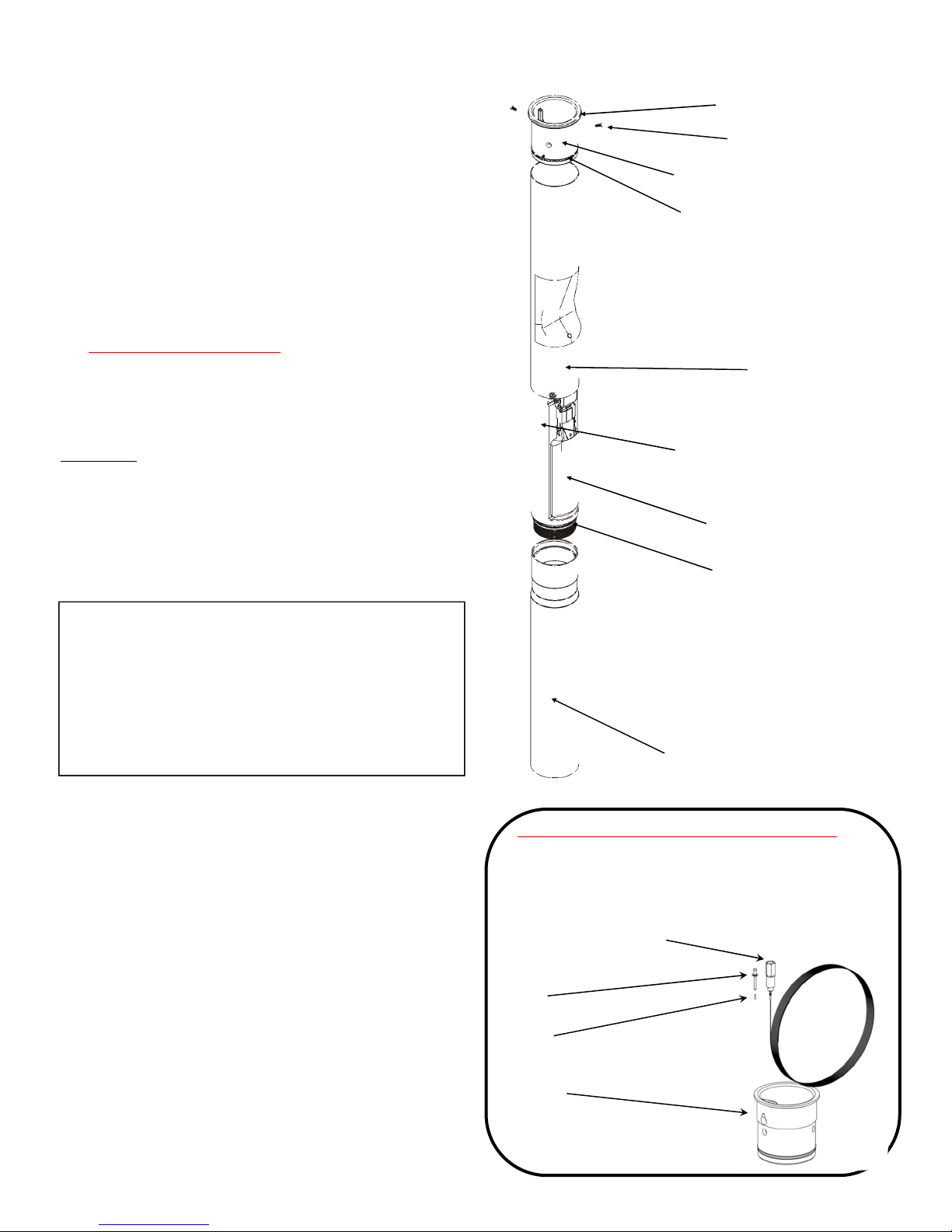
71SO Parts Diagram
Upper O-Ring Gasket
Screws, Qty 3
Inlet Tube
Polypak Seal
Upper Drop Tube
Valve Body
Float
Lower O-Ring
Lower Tube
Alternate Components - Testable Versions
Note: all components are the same except the
socket adaptor & cable assembly, rivet, testable
inlet tube, and ferrule.
Socket Adaptor & Cable
Assembly
Rivet
Ferrule
Testable Inlet
Tube
3
Page 4
IMPORTANT: The instructions below for the 71SO
Overll Prevention Valve are written for the initial
stage shuto at 95%, but can be adjusted to shuto
at any desired tank capacity. Please contact the Authority Having Jurisdiction (AHJ) and review local,
state, and national codes to determine the regulatory requirements governing shut-o capacity in your
region, as well as take into account other considerations such as extreme tank tilt. In all cases, the upper tube must protrude into the tank at least 6 1/2”
to ensure that the valve can shut o ow into the
tank completely before the top of the tank is wetted
as per EPA requirements.
HOW TO LOCATE THE POSITION OF THE 71SO AT
95% TANK CAPACITY
(Shut-o points can be adjusted to any capacity to
comply with AHJ Requirements)
The length of the upper tube and the placement of the
71SO valve body determine the shut-o point. Following the standard instructions for the OPW 71SO will provide for initial shuto at 95%. In all cases, the upper
tube length must be a minimum of 6-1/2" plus the
length of the riser pipe. All length measurements are in
inches.
INSTRUCTIONS
1) Find tank capacity (in gallons) from tank calibration
chart provided by tank manufacturer.
2) Calculate 95% of capacity
3) Locate the 95% volume number on the tank calibration chart.
4) Find the dipstick number (X) which corresponds to
the 95% tank volume. And, nd the dipstick number (Y) which corresponds to the 100% volume.
5) Subtract the dipstick number (X) from the tank diameter (Y) to nd the upper tube reference number
(Z).
(Y) - (X) = (Z)
6) Subtract 2" from (Z) to nd the upper tube depth
(C).
(Z) - 2" = C
7) Is C less than 6-1/2"?
NO Upper tube length is C plus the distance from
the top of the Face Seal Adaptor installed on
the riser pipe to the inside, top lip of the storage
tank (A).
Upper Tube Length = C + (A)
For testable models only, ending in “T”:
Upper Tube Length = C + (A) – 1-1/2”
YES Upper tube length is 6-1/2” plus the riser pipe
measurement (A).
Upper Tube Length = 6-1/2” + (A)
For testable models only, ending in “T”:
Upper Tube Length = 6-1/2” + (A) - 1-1/2”
NOTE: You must nd the actual tank capacity number that correlates to the 6-1/2” + (A) depth for the
station records. This number may also be used for
the purposes of calibrating an electronic tank level
system.
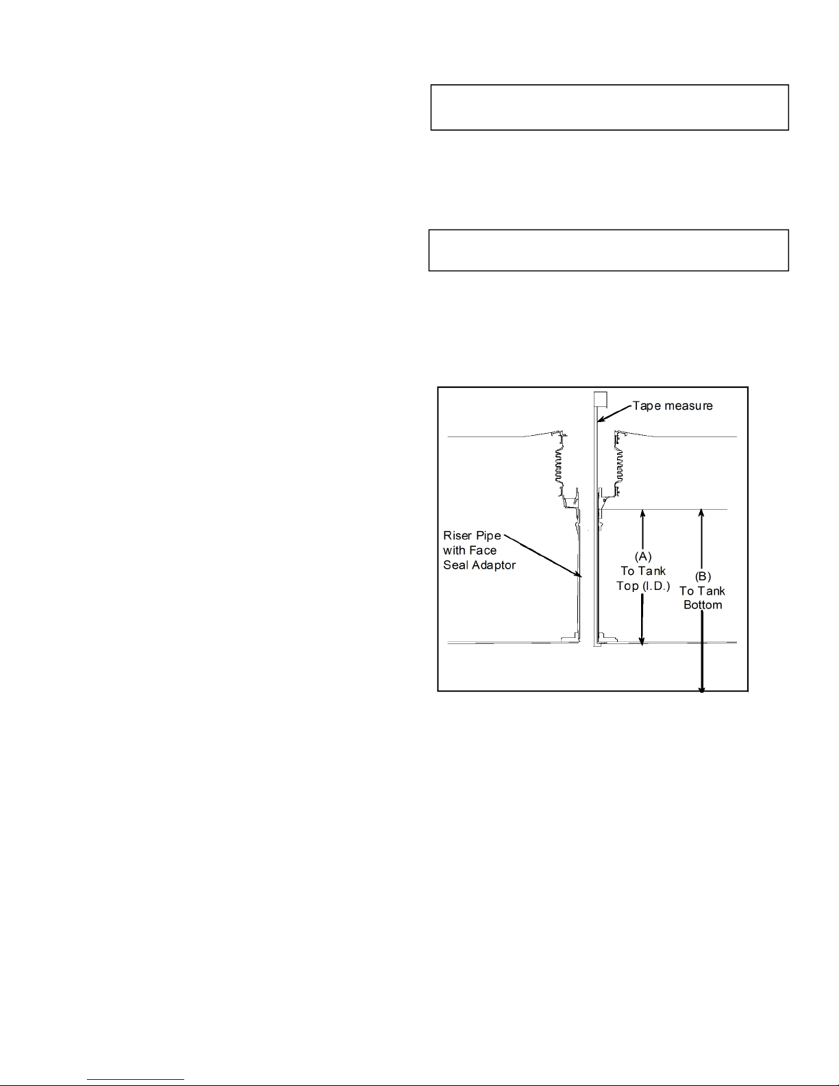
Figure 1
EXAMPLE
1) For an Owens-Corning Model G-3 Fiberglass® Tank
Calibration Chart:
Tank Capacity - 10,000 gal., nominal 9,403 gal.
NOTE: Use actual capacity only
2) 95% of actual tank capacity = 0.95 x 9403 gal. =
8933 gal.
3) The closest number which is less than 8933 gal. Is
8910 gal. Choosing the closest number less than
95% of actual capacity ensures that the initial
shuto will occur when the tank is no more than
95% full.
4) The calibration chart reading of 8910 gal. corresponds to a dipstick measurement of 82”.
4
Page 5
5) Dipstick number (X) = 82”
Tank diameter (Y) = 92”
(Y) - (X) = (Z) (92” - 82” = 10”)
(Z) = 10”
6) (Z) - 2” = C (10” - 2” = 8”)
C=8”
7) Is 8” less than 6-1/2”?
NO Measure the distance from the top of the FSA-
400 Face Seal Adaptor installed on the riser pipe
to the inside, top lip of the storage tank and obtain measurement (A).
Upper tube length = C + (A)
For testable models only, ending in “T”: Upper Tube
Length = C + (A) - 1-1/2”
ASSEMBLY INSTRUCTIONS
IMPORTANT: Each of the numbered steps in the instal-
lation instructions are designed as a CHECK LIST to ensure proper installation and trouble free operation of
the OPW 71SO Overll Prevention Valve.
Read and follow these steps carefully, checking them
o as you proceed.
Figure numbers correspond to step numbers for easy
reference.
STEP 1: MEASURE
Install the OPW Face Seal Adaptor and the OPW Threadon Spill Container on the Fill Riser (Refer to the Installation Instructions Supplied with the Spill Container). Insert a tape measure through the riser pipe and hook it
under the inside of the tank in the lengthwise direction.
Measure the distance from the top of the Face Seal
Adaptor threads inside the base of the spill container
bucket just below the drain valve outlet window to the
inside, top lip of the storage tank (Dim. “A”) (See Figure
1 &1A).
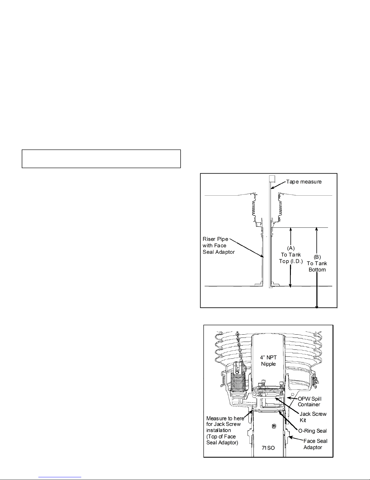
The top ange on the 71SO will rest on the Face Seal
Adaptor just below the drain valve outlet, and be
locked in place between the Face Seal Adaptor and the
4" nipple that is installed in the spill container with the
Jack Screw Kit (See Figure 1A). (For riser pipe congurations other than that shown, consult installation
drawings or use other necessary means to measure Dimension “A”).
Using a tape measure, measure the distance from the
top of the Face Seal Adaptor in the spill container to the
bottom of the tank (Dim. “B”).
IMPORTANT: Inspect the riser pipe for any foreign material. Over spray from tank relining or any internal
burrs inside of pipe must be removed prior to installation. Failure to have an unobstructed riser pipe may
prevent proper installation and operation of the valve.
The 71SO is designed for installation into schedule 40
riser pipes. The 71SO cannot be installed into schedule
80 riser pipes.
STEP 2: MARK THE TUBE
Use the result from Step 1 and HOW TO LOCATE THE
POSITION OF THE 71SO AT 95% TANK CAPACITY to
mark the upper tube. Measure the distance from the
seam where the upper tube and valve body meet. Use
a tape measure to mark the calculated upper tube
length onto the upper tube. See Figure 2.
Figure 1
Figure 1A
5
Page 6
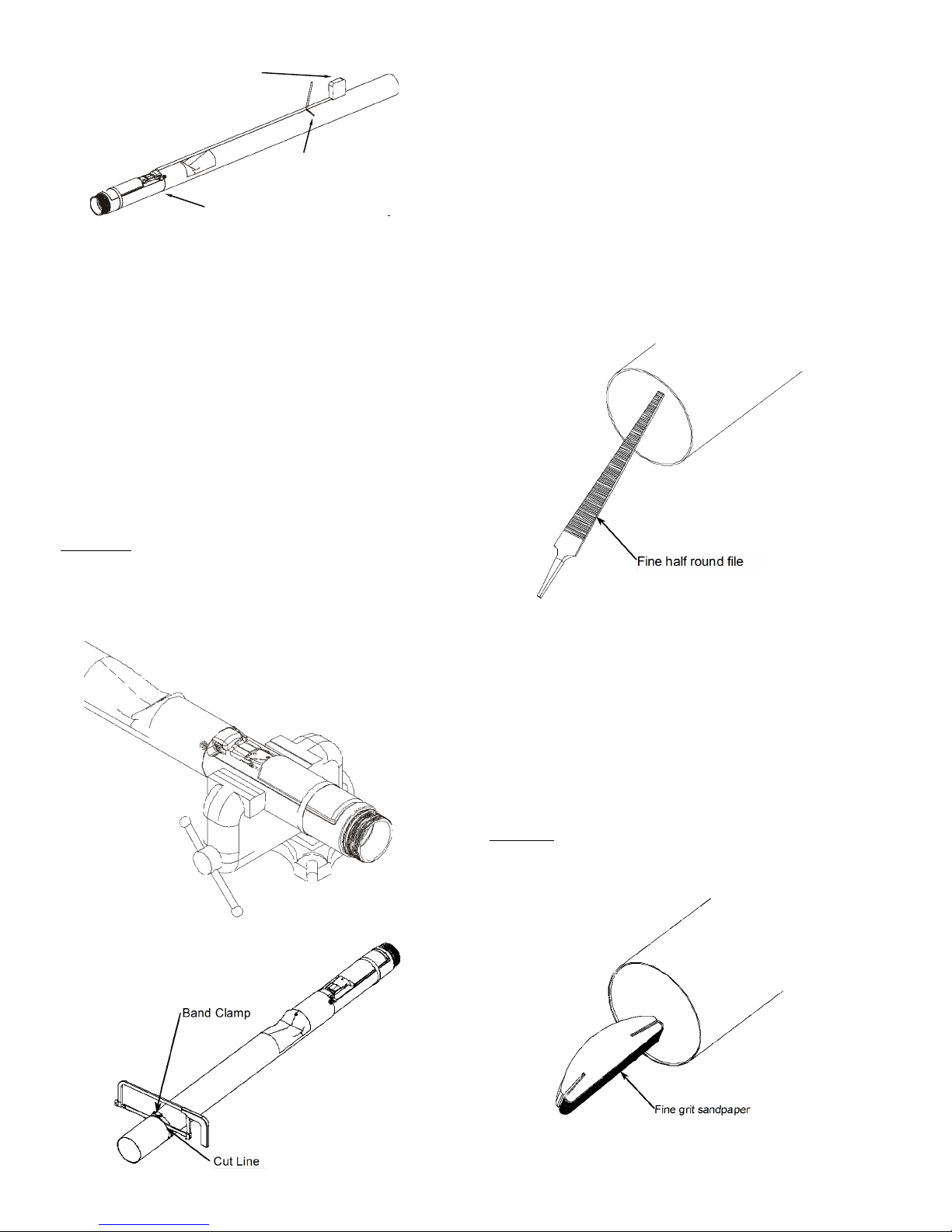
Figure 2
Tape measure
Seam
Mark Upper Tube
(Cut Line)
STEP 3: CUT THE UPPER DROP TUBE
Attach the supplied band clamp to the upper tube just
below the mark and ensure that it is assembled square
to the tube. The clamp can be used as a guide for making a square cut. If a vise is used, clamp on the valve
body casting only to avoid damage to the oat and
tubes (See Figure 3A). Carefully saw through the tube
squarely, at the mark made in Step 2. Use a hacksaw
with a new ne-tooth blade. Rotating the upper tube
as the sawing progresses will minimize run out and ensure a square 90-degree cut. Remove the band clamp
after tube is cut.
CAUTION - DO NOT use a pipe or tubing cutter to cut
the upper drop tube, this may damage the tube,
causing it to be out of round thereby prohibiting
assembly of the unit.
Figure 3A
IMPORTANT: Remove all chips and shavings generated
in steps 3 thru 5 out of the cut end of the tube. DO NOT
remove chips and shavings by dumping thru valve
body.
STEP 4: FILE THE UPPER DROP TUBE
File the upper tube square, and remove any burrs or
rough edges. Make sure the cut is at and square.
IMPORTANT: Carefully le a good chamfer on the inside edge of the drop tube to provide a lead-in for the
polypak seal and inlet tube installed in Step 8.
Figure 4
STEP 5: SAND THE UPPER DROP TUBE
Sand the inside of the drop tube with sandpaper and/or
steel wool to remove all burrs and sharp edges. After
sanding wipe down the inside of the tube with a clean
rag from the top to approximately 4 inches down to
remove any debris.
Caution: Failure to properly chamfer, sand, and
clean the drop tube may cut the seal and result in a
failure of a pressure decay leak test.
Figure 5
Figure 3B
6
Page 7
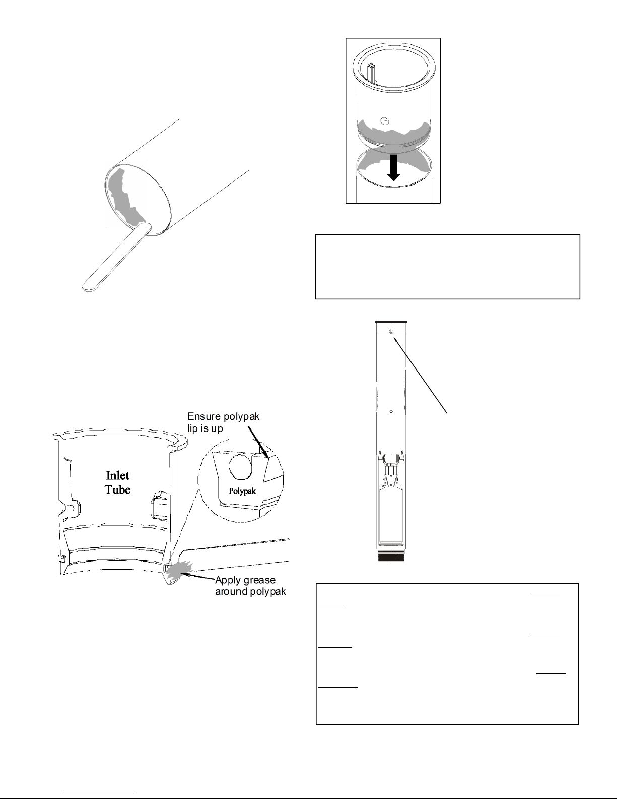
STEP 6: APPLY GREASE TO DROP TUBE
Apply black moly grease to the inside diameter of the
upper drop tube. Make sure coverage is completely
around the tube as shown in Figure 6.
Figure 6
STEP 7: APPLY GREASE TO POLYPAK SEAL
Ensure that the polypak seal is installed on the inlet
tube with the lip up as shown in Figure 7. Apply black
moly grease to the polypak as shown. Make sure coverage is completely around the polypak seal.
Figure 8
NOTE: Testable inlet tube must have cable port in
line with oat. Testable inlet tube bottoms out on
stop, it does not bottom out on inlet ange. See Fig-
ure 8A
Figure 7
STEP 8: INSTALL INLET TUBE
Insert the inlet tube into the upper tube until the upper
tube seats against the ange on the inlet tube. Ensure
polypak is inserted evenly and stays in inlet tube
groove.
Cable port must be in
line with oat
Figure 8A
Testable Models Only
SEE PAGE 8 FOR INSTRUCTIONS USING THE 71SOTOOL.
SEE PAGE 9 FOR INSTRUCTIONS USING THE 71SOTOOLC.
SEE PAGE 10 FOR INSTRUCTIONS USING THE 71SOTOOLCT.
Note: testable 71SO models ending with a “T” require the
71SO-TOOLCT or modied 71SO-TOOL or 71SO- TOOLC
7
Page 8
71SO-TOOL PROCEDURE BELOW,
FOR 71SO-TOOLC, SEE PAGE 9
FOR 71SO-TOOLCT, SEE PAGE 10
Note: 71SO-TOOL can only be used with testable
overll valves if modied as shown below. A 2”
wide slot must be added to accommodate cast lug.
Add 2” wide
slot to use with
testable valves
71SO-TOOL Modications for Testable Inlet
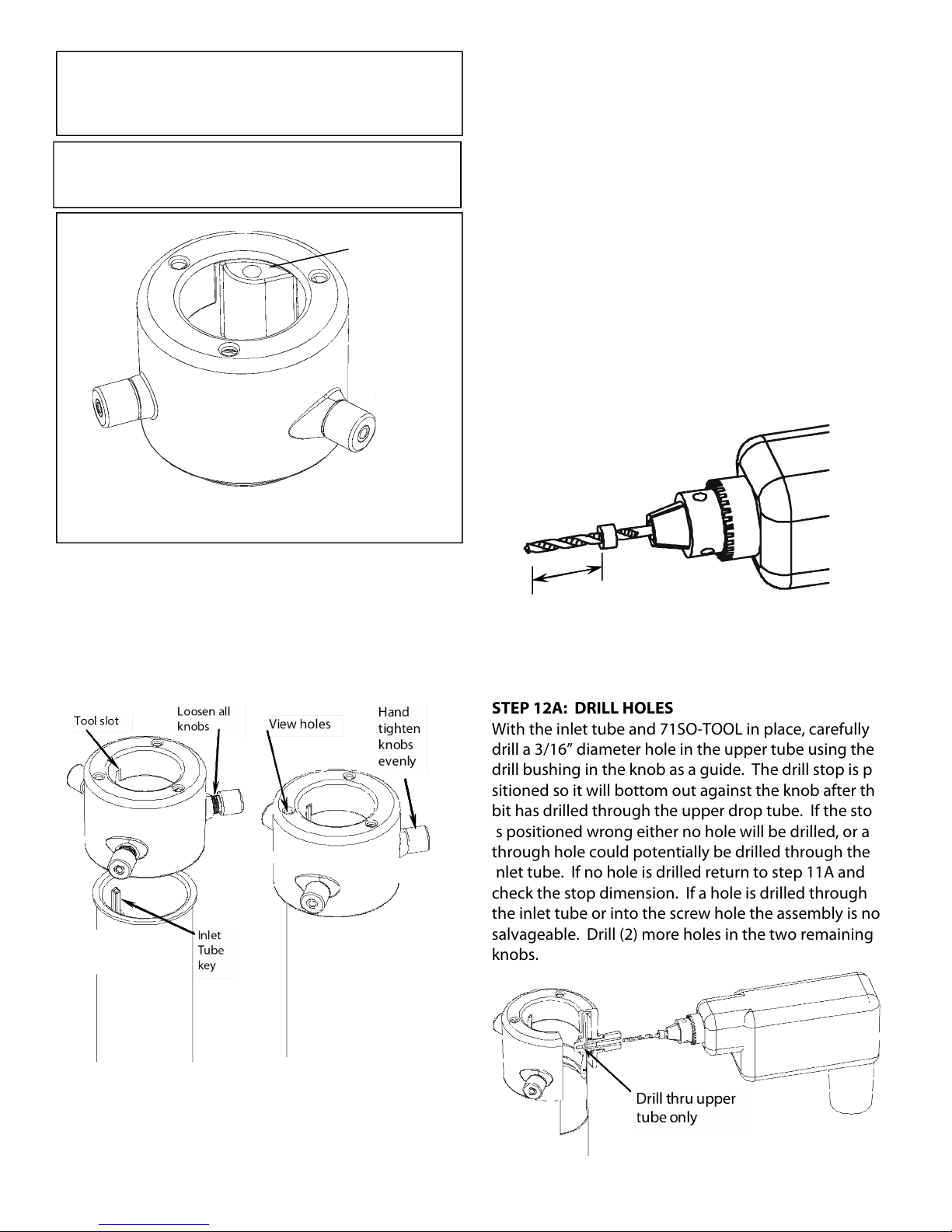
STEP 9A: INSERT 71SO-TOOL OVER INLET TUBE
To install the 71SO-TOOL (sold separately) over the inlet
tube, rst loosen all three knobs, so the tool can pass
freely over the inlet tube ange. Align the slot on the
tool with the key on the inlet tube and insert the tool
down. See Figure 9A.
STEP 10A: TIGHTEN THE 71SO-TOOL
Use the three view holes to ensure that the tool seats
out at against the top of the inlet tube. To prevent
vertical movement of the tool during drilling, hand
tighten all three knobs evenly to the upper drop tube.
See Figure 10A.
STEP 11A: PREPARE DRILL AND BIT
Conrm that the stop on the 3/16” drill bit supplied
with the 71SO-TOOL is in the correct position before
drilling. The stop is factory installed at a distance between 2” to 2-1/16” from the tip with the 71SO-TOOL. If
the stop is not at the correct position it must be xed
before drilling.
CAUTION: If the drill stop is not in the proper location failure of a pressure decay leak test may result.
Tip to stop dimension must be
2” to 2-1/16”.
Figure 11A
STEP 12A: DRILL HOLES
With the inlet tube and 71SO-TOOL in place, carefully
drill a 3/16” diameter hole in the upper tube using the
drill bushing in the knob as a guide. The drill stop is positioned so it will bottom out against the knob after the
bit has drilled through the upper drop tube. If the stop
is positioned wrong either no hole will be drilled, or a
through hole could potentially be drilled through the
inlet tube. If no hole is drilled return to step 11A and
check the stop dimension. If a hole is drilled through
the inlet tube or into the screw hole the assembly is not
salvageable. Drill (2) more holes in the two remaining
knobs.
Figure 9A
Figure 10A
Figure 12A
8
Page 9

71SO-TOOLC PROCEDURE BELOW,
FOR 71SO-TOOL, SEE PAGE 8
FOR 71SO-TOOLCT, SEE PAGE 10
Note: 71SO-TOOLC can only be used with testable
overll valves if modied as shown below.
Add a 10-24 UNC thread or similar
to all three legs of the 71SOTOOLC in the area shown. Use set
screws to secure tool to upper
tube.
71SO-TOOLC Modications for Testable Inlet
STEP 9B: INSERT 71SO-TOOLC OVER INLET TUBE
To install the 71SO-TOOLC (sold separately) over the
inlet tube, rst loosen the thumb screw, so the tool can
pass freely over the inlet tube ange. Align the slot on
the tool with the key on the inlet tube and insert the
tool down. See Figure 9B.
STEP 10B: TIGHTEN THE 71SO-TOOLC
Ensure that the tool seats at against the top of the inlet
tube. To prevent vertical movement of the tool during
drilling, hand tighten the thumb screw against the upper drop tube. See Figure 10B.
STEP 11B: PREPARE DRILL AND BIT
Conrm that the stop on the 3/16” drill bit supplied
with the 71SO-TOOLC is in the correct position before
drilling. The stop is factory installed at a distance between 1-3/16” to 1-1/4” from the tip with the 71SOTOOLC. If the stop is not at the correct position it must
be xed before drilling.
CAUTION: If the drill stop is not in the proper location failure of a pressure decay leak test may result.
Figure 11B
STEP 12B: DRILL HOLES
With the inlet tube and 71SO-TOOLC in place, carefully
drill a 3/16” diameter hole in the upper tube using the
hole in the 71SO-TOOLC as a guide. The drill stop is positioned so it will bottom out against the tool after the
bit has drilled through the upper drop tube. If the stop
is positioned wrong either no hole will be drilled, or a
through hole could potentially be drilled through the
inlet tube. If no hole is drilled return to step 11B and
check the stop dimension. If a hole is drilled through
the inlet tube or into the screw hole the assembly is not
salvageable. Drill (2) more holes in the two remaining
guide holes.
Figure 12B
9
Page 10

71SO-TOOLCT PROCEDURE BELOW,
FOR 71SO-TOOL, SEE PAGE 8
FOR 71SO-TOOLC, SEE PAGE 9
STEP 9C: INSERT 71SO-TOOLCT OVER INLET TUBE
To install the 71SO-TOOLCT (sold separately) over the
inlet tube, rst loosen the thumb screws, so the tool can
pass freely over the inlet tube ange. Align the slot on
the tool with the key on the inlet tube and insert the
tool down. See Figure 9C .
Loosen
thumb
screws
Tool Slot
Hand tighten
thumb screws
Inlet
Tube
Key
Figure 11C
STEP 12C: DRILL HOLES
With the inlet tube and 71SO-TOOLCT in place, carefully
drill a 3/16” diameter hole in the upper tube using the
hole in the 71SO-TOOLCT as a guide. The drill stop is
positioned so it will bottom out against the tool after
the bit has drilled through the upper drop tube. If the
stop is positioned wrong either no hole will be drilled,
or a through hole could potentially be drilled through
the inlet tube. If no hole is drilled return to step 11C
and check the stop dimension. If a hole is drilled
through the inlet tube or into the screw hole the assembly is not salvageable. Drill (2) more holes in the two
remaining guide holes.
Figure 9C
Figure 10C
STEP 10C: TIGHTEN THE 71SO-TOOLCT
Ensure that the tool seats at against the top of the inlet
tube. To prevent vertical movement of the tool during
drilling, hand tighten the thumb screws against the upper drop tube. See Figure 10C.
STEP 11C: PREPARE DRILL AND BIT
Conrm that the stop on the 3/16” drill bit supplied
with the 71SO-TOOLCT is in the correct position before
drilling. The stop is factory installed at a distance between 1-3/16” to 1-1/4” from the tip with the 71SOTOOLCT. If the stop is not at the correct position it must
be xed before drilling.
CAUTION: If the drill stop is not in the proper location failure of a pressure decay leak test may result.
Figure 12C
10
Page 11

STEP 13: DIMPLE FIRST HOLE
Remove tool. Remove any chips or burrs from the drilling operation. Place the assembly on a solid surface.
Using the punch supplied with the 71SO-TOOL, 71SOTOOLC, and 71SO-TOOLCT, align the tip of the punch
with the drilled hole and dimple the upper drop tube by
striking the punch with a hammer until the drop tube is
formed into countersunk hole in the inlet tube. After
punching, remove any chips that may have fallen into
the inlet tube screw hole.
Figure 13
STEP 14: ASSEMBLE FIRST SCREW
Ensure that the drop tube was formed into the countersunk screw hole as shown in Figure 14 if not return to
Step 13. Apply black moly grease to screw and tighten
rst screw into inlet tube with a screwdriver. Use only
the taptite screws that are supplied with the unit. Seating torque is 20 in-lbs min. to 35 in-lbs max. Screw head
should be ush with the drop tube. Do not over tighten.
Figure 14
STEP 15: DIMPLE REMAINING HOLES
Remove any chips or burrs from the drilling operation.
Dimple the next (2) holes as done in Step 13. Make sure
the assembly is on a solid surface when punching. After
punching, remove any chips that may have fallen into
the inlet tube screw hole.
Figure 15
STEP 16: ASSEMBLE OTHER SCREWS
Apply black moly grease to screws and tighten the other (2) screws into inlet tube with a screwdriver as done
in Step 14. Use only the taptite screws that are supplied
with the unit. Seating torque is 20 in-lbs min. to 35 inlbs max. Do not over tighten.
STEP 17: APPLY GREASE TO LOWER O-RING AND
BODY THREADS
Apply black moly grease to the lower tube o-ring and
body threads as shown. Make sure coverage is completely around the o-ring. Install o-ring in groove just
above threads.
Figure 17
11
Page 12

STEP 18: LOWER TUBE ASSEMBLY
If a vise is used, clamp on the valve body casting only to
avoid damage to the oat and tubes. Thread the lower
tube onto the valve body until the lower tube bottoms
out on valve body. Tube can be tightened by hand or
with a strap wrench. If a strap wrench is used try to position it on the threaded insert portion of the lower tube
to prevent damaging the tube.
Figure 18
NOTE: Before installing the valve in the tank, a pressure test can be performed on the valve to check for
vapor tightness. Seal o both ends of the tube with
inatable plumber’s plugs. Apply a maximum 10"
W.C. (1/3 PSI) air pressure. If pressure does not hold
and a leak can be located with soap solution, do not
install the valve. Send the valve back to OPW for
warranty evaluation.
CAUTION: Do not over-pressurize. Excess pressure
can damage the valve.
STEP 19: CUT LOWER TUBE
Measuring from the underside of the inlet tube ange,
mark the overall length of the drop tube a distance of
(B) minus 6". Determine dimension (B) from the measurements taken in Step 1, Figure 1 (Top of the Face Seal
Adapter below the drain valve outlet in the spill container to the bottom of the tank). Saw o the excess
tube at a 45-degree angle or per local codes or requirements and le o any sharp burrs (Refer to Figure 24).
Optional: Install the OPW Tank Bottom Protector on
the lower tube (Refer to Installation instructions supplied with the Tank Bottom Protector).
IMPORTANT: Remove all chips and shavings out of the
cut end of the tube. DO NOT remove chips and shavings by dumping thru valve body.
FOR STANDARD VAPOR TIGHT MODELS, PROCEED
TO STEP 20 ON PAGE 14.
FOR TESTABLE MODELS, PROCEED TO PAGE 13.
12
Page 13

TESTABLE PROCEDURE ONLY, FOR STANDARD MODELS, PROCEED TO NEXT PAGE.
STEP 1T: INSTALL SOCKET ADAPTOR ASSY
Put cable thru threads in inlet tube and out thru cable
port on side of inlet tube. Thread the socket adaptor
assembly nger tight into the inlet tube. Note: the cable port on the inlet tube must be in line with the oat
as shown previously in Figure 8A.
Socket
adaptor
assembly
Cable
port
Figure 1T
STEP 2T: PASS CABLE THRU FERRULE
Pass cable thru ferrule. Loop cable and then pass cable
back thru ferrule. Keep ferrule loose until cable length
is determined in the next step. Note: if cable end frays
it may be necessary to trim the cable again to pass thru
ferrule.
1/8” mandrel
rivet
Ferrule
Trim
cable
after
step 3T
Loop
Figure 2T
STEP 3T: DETERMINE CABLE LENGTH
Run cable along upper tube and over the top plate on
the oat bracket as shown. With the oat in the down
position (as shown in Figure 3T) align loop in cable with
rivet and top hole in oat bracket. Use the rivet as a
template to size the loop in the cable and pull cable
tight and crimp ferrule with crimping tool / pliers onto
cable at this location. Trim excess cable with wire cutter / scissors. For reference, from the seam where the
upper tube and valve body meet to the end of the cable
after trimming will require approximately 3.5” of cable.
Cable over oat bracket
Seam
Figure 3T
STEP 4T: ATTACH CABLE TO FLOAT BRACKET
Ensure cable is over the oat bracket. Using the supplied rivet align loop in cable with top hole in oat
bracket and pass rivet thru cable loop and oat bracket
hole. Using rivet tool for 1/8” dia mandrel attach rivet
and cable to the oat bracket. See last page for list of
replacement cable parts.
Attach rivet to top hole
Figure 4T
STEP 5T: ENSURE PROPER CABLE OPERATION
Unthread the socket adaptor assembly from the inlet
tube and ensure oat and poppet move freely when
socket adaptor assembly is pulled on. It should only
require 3” to 4” of movement in order to actuate the
oat and poppet. Thread socket adaptor assembly nger tight into inlet tube after testing.
13
Page 14

STEP 20: PREPARE FILL RISER FOR VALVE INSERTION
IMPORTANT: Inspect the riser pipe for any foreign ma-
terial. Over spray from tank relining or any internal
burrs inside of pipe must be removed prior to installation. Failure to have an unobstructed riser pipe may
prevent proper installation or operation of the valve.
Thoroughly clean top of riser pipe.
STEP 21: REMOVE ELASTIC BAND
Remove the elastic band securing the oat to the valve
body. The oat will move into an outward position.
STEP 22: INSERT DROP TUBE
Make sure the upper O-Ring gasket is under the ange
of the inlet tube. Hold the oat down against the valve
body and slowly insert the drop tube overll valve into
the riser pipe. Do not force valve into the riser pipe. If
any obstruction or foreign matter interferes with
smooth insertion of the valve, the riser pipe must be
cleared.
WARNING
Failure to follow the assembly
and installation instructions or
use of excessive force to insert
the OPW 71SO will VOID THE
WARRANTY.
Diculty in removing the existing
ll tube (if there is one) means
there may be an obstruction in the
riser pipe. Look for burrs, deformations, excess tank lining material or other projections that may
interfere with easy insertion of the
OPW 71SO. The 71SO is designed
for insertion into schedule 40 pipe. If
Figure 22
schedule 80 pipe has been used for the
riser, the 71SO cannot be installed. If seamed pipe has
been used, the internal weld bead may interfere with
the OPW 71SO and prevent installation. If the OPW
71SO won’t slip in easily DON’T FORCE IT! Damage to
the valve may result if excess force is used. Examine the
riser pipe carefully; determine the nature of the obstruction; take appropriate steps to remove it.
STEP 23: CHECK INSTALLATION
Insert the drop tube all the way into the tank until the
ange and gasket seat onto the top of the Face Seal
Adaptor. The oat will swing out into the operating
position as it passes into the tank.
Figure 23
Make sure that the oat is aligned along the length of
the tank. The length of the tank can easily be determined by locating other manholes or pump boxes that
are installed around other tank ttings. Look into the
drop tube and align the deector with the length of the
tank.
For testable models only: Unthread the socket adap-
tor assembly from the inlet tube (a 3/8” square drive
extension will attach to the socket adaptor, secure all
tools to ensure they don’t fall into the tank or valve) and
ensure oat and poppet move freely when socket adaptor assembly is pulled on. When looking down into the
upper tube ensure poppet is visible when socket adaptor is pulled and resets properly when socket adaptor is
released. See page 17 for full testing details. If poppet
does not actuate freely take appropriate steps to correct
before proceeding.
CAUTION: No obstruction in the tank can be within
14" from the center of the riser pipe or the valve
may not operate properly (See Figure 24).
STEP 24: ALIGN VALVE
Install the OPW Jack Screw Kit and a 4" NPT nipple to
lock the valve in place. Refer to the Installation Instructions supplied with the Jack Screw Kit. For testable
models ensure that the socket adaptor is aligned so
it does not interfere with the jack screw kit. (see Fig-
ure 24A). Install the Rotatable Product Adaptor (Refer
to Installation Instructions supplied with the Product
Adaptor.) Make sure that the valve does not rotate
while tightening the adaptor by observing the position
of the deector. The valve must remain aligned
along the length of the tank as in Step 23. Repeat
this step as necessary to assure proper valve alignment.
14
Page 15

Figure 24
Figure 24A
Orient socket
adaptor between jack
screw bolts
FOR TESTABLE MODELS ONLY: Check installation
again as done in Step 23 to ensure poppet actuates and
resets properly. See page 17 for full testing details. Apply pipe dope to the socket adaptor threads. Pipe dope
should be a non-hardening gasoline resistant pipe
thread seal compound. Install socket adaptor and
torque to 3.5 ft-lbs (42 in-lbs) minimum to 5.0 ft-lbs (60
in-lbs) maximum. After installing socket adaptor where
required, pressure test testable overll valve per CARB
TP201.1D to ensure valve is vapor tight.
15
Page 16

STEP 25: INSTALL WARNING PLATE
Bend the three warning plate ears down then slide the
tie wrap over the warning plate ears and position warning plate against riser pipe approximately 1" below the
adaptor. Tighten the tie wrap securely. The valve is
now fully installed and in operating position.
NOTE: the warning plate includes important warnings, operating parameters, and listing information
and must be installed.
Figure 25
STEP 26: VALVE REMOVAL
The valve can be removed for tank leak testing, inspection, etc., by removing the Rotatable Product Adaptor,
the 4" nipple, and the Jack Screw Kit. Reinstall per the
above instructions.
For testable models only: It is not necessary to re-
move the valve to check poppet movement / function.
See Page 17 for full testing details.
STEP 27: ELECTRONIC LIQUID LEVEL MONITORING
If an electronic level monitor is installed, it must be calibrated to match the top of the 71SO valve body, which
must correlate with 95% of the actual tank capacity.
Figure 26 - Product Identication
16
Page 17

TEST INSTRUCTIONS
POPPET & FLOAT MOVEMENT
FOR TESTABLE MODELS ONLY
TOOLS NEEDED FOR TESTING:
1. 1/4” square drive extension or 3/8” square drive extension with 3/8” to 1/4” socket adapter.
2. Torque wrench / 1/4” or 3/8” square drive ratchet
wrench.
3. Pipe dope.
4. Flashlight (optional).
TEST STEP 1:
Remove spill container cover and ll cap from ll adapter and look down into the tube and make sure no debris
or foreign objects are present. If debris or foreign objects are present take appropriate steps before proceeding. Look down into the tube and ensure poppet is
completely protected by the deection shield. See Test
Figure 1. If poppet is exposed and tank is not full the
overll valve should be replaced. A ashlight may help
when inspecting the tube.
TEST STEP 2:
Unthread the socket adaptor assembly from the inlet
tube using a 1/4” square drive extension and wrench.
The extension will attach to the socket adaptor. Secure
all tools to ensure they don’t fall into the tank or valve.
With the extension still attached pull on the socket
adaptor and cable assembly and ensure oat and poppet move / function properly. It should only require 3”
to 4” of movement and less than 5 lbs of force in order
to actuate the oat and poppet. When looking down
into the upper tube ensure poppet is visible and moves
into the ow path (see Test Figure 1 & 2) when socket
adaptor is pulled and resets properly when socket adaptor is released. If poppet does not actuate freely take
appropriate steps to correct.
TEST STEP 3:
Apply pipe dope to the socket adaptor threads. Pipe
dope should be a non-hardening gasoline resistant pipe
thread seal compound. Make sure poppet and oat
have reset properly and are not visible then install socket adaptor and torque to 3.5 ft-lbs (42 in-lbs) minimum
to 5.0 ft-lbs (60 in-lbs) maximum. After installing socket
adaptor, to ensure vapor tightness, OPW recommends
conducting pressure testing per CARB TP201.1D. Some
areas may require pressure testing of overll valve per
CARB TP201.1D to ensure valve is vapor tight. If the
drop tube fails pressure testing it may be necessary to
check the seal at the poppet adaptor threads. Reinstall
ll cap and spill container cover after testing.
Open Poppet Closed Poppet
Test Figure 1
Open
Poppet
Test Figure 2
Socket
adaptor
Pull on extension and
socket adaptor
Closed
Poppet
Float moves
up
17
Page 18

PREVENTIVE MAINTENANCE
Annually, inspect the apper in the 71SO to see that it is
open by looking down the drop tube opening (see inspection procedure below). Test the 71SO drop tube
seals with CARB procedure TP-201.1D. If the drop tube
seal passes testing, no further maintenance is required.
If the drop tube fails testing, replace the drop tube seal
with OPW P/N: H11931M for 4” Tubes. Re-test the 71SO
drop tube with CARB procedure TP-201.1D. The lower
tube o-ring seal OPW P/N: H14840M can also be replaced. If this does not correct the leak the 71SO needs
to be replaced.
FOR TESTABLE MODELS ONLY: The socket adaptor
can be removed and poppet and oat movement and
function inspected without removing the valve. See
Page 17 for full testing details. If replacement parts are
needed for testable models the following items are
available: OPW P/N 206741 Testable Inlet Tube S/A,
206740 Socket Adaptor and Cable Assembly, and 61SOK
-0001 Float Kit.
CAUTION: Do not insert any foreign object into drop
tube if apper is in the closed position. For example, a tank level measuring stick. This will damage
the valve and void the Warranty. ALWAYS check
apper location before “sticking” the tank. If apper is in the closed position, the tank is either overlled and you need to wait until the liquid level goes
down or the 71SO is damaged and needs to be replaced.
Inspection Procedure to Ensure Proper Operation
Note: For testable models valve does not need to be
removed from tank. See page 17 for testable instructions.
INSP 1. Remove the overll valve from the tank as described in step 26.
INSP 2. Visually inspect the valve for damage. Make
sure no debris or foreign objects are in or on the valve.
Good Valve
Bad Valve
Figure 27
Note: Figure 27 shows poppet location with oat arm
not activated.
INSP 4. Inspect the oat by lifting upward. The oat
should move freely without any binding. See Figure
28.
INSP 3. With the oat in the normal (down) position,
visually inspect the valve to ensure the poppet is not
exposed outside the deection shield. See Figure 27.
Figure 28
INSP 5. View down the tube to ensure the poppet is
moving into the ow path when lifting the oat. See
Figure 29.
18
Page 19

Figure 29
INSP 6. If there is no apparent damage or restrictions
reinstall the valve per the above instructions and test
per local requirements.
71SO Performance Specications
This Overll Prevention Valve has been manufactured
and tested to, and met, the following California specications. Performance Requirement: Leak rate to be less
than or equal to 0.17 CFH@2.0” W.C.
Torque Specication
Taptite Screws, #10-24 thread cutting, 20 in-lbs minimum to 35 in-lbs maximum. Testable Models Only:
Socket Adaptor, 1/4” NPT, 3.5 ft-lbs (42 in-lbs) minimum
to 5.0 ft-lbs (60 in-lbs) maximum.
IMPORTANT: Leave these installation instructions
and maintenance procedures with the station operator.
19
Page 20

Appendix A
71SO Overll Valve Upper Tube Calculation Worksheet
Important: This is meant to be supplemental worksheet and not a substitute to following the installation
manual instructions. All length measurements are in inches. Please contact the Authority Having Jurisdiction (AHJ) and review local, state, and national codes to determine the regulatory requirements governing
shut-o capacity in your region, as well as take into account other considerations such as extreme tank tilt.
Desired tank capacity for shut-o: SO%= _______
Dipstick Number on Tank Chart that corresponds to 100% volume (Y) =
Dipstick Number on Tank Chart that corresponds to SO% (X) =
Upper Tube Reference Number Z=Y-X
2
Upper Tube Depth Inside Tank C = Z-2”
Distance from top sealing surface for 71SO Lip
top of Storage Tank
2
For Non-Testable 71SO models only
1
to inside the
A=___________
(Y)
(X)
(Z)
(C)
In all cases for non-testable 71SO models, the top of the valve body must protrude at least 6 ½” into the tank to
provide a minimal clearance for proper operation.3 Additionally the total Upper Tube Length must be at least 16”
of length to include the protective bend in the tube.
Is C less than 6 ½” Yes / No
If NO, Upper Tube Length (D)= C + A
If YES, Upper Tube Length (D)= 6 ½ “+ A
Upper Tube Length = ___________
For Testable 71SO models only
In all cases for Testable 71SO models, the top of the valve body must protrude at least 6 ½” into the tank to provide
a minimal clearance for proper operation.3 Additionally the total Upper Tube Length must be at least 14 ½” of
length to include the protective bend in the tube.
Is C less than 5” Yes / No
If NO, Upper Tube Length (D)= C + A – 1 ½ “
If YES, Upper Tube Length (D) = 6 ½” + A – 1 ½ “
Upper Tube Length = ___________
1
Sealing surface may be the top of the Face Seal Adaptor, the built in sealing ledge inside some spill containers, or on non-
vapor tight applications the top of the pipe nipple
2
Some Underground Storage tanks utilize a manway system at the top. Make sure to use the top of the storage tank for
measurement and not to top of the manway. Consult your underground tank manufacturer for height of the manway
3
This measurement is taken from the seam where the upper tube is attached to the valve body to the inside of the tank top.
20
Page 21

Appendix B
71SO Overll Valve in Tank Shut o Level Worksheet
Important: This is meant to be supplemental worksheet and not a substitute to following the installation
manual instructions. All length measurements are in inches. Please contact the Authority Having Jurisdiction (AHJ) and review local, state, and national codes to determine the regulatory requirements governing
shut-o capacity in your region, as well as take into account other considerations such as extreme tank tilt.
Take the following measurements with the valve installed in the tank:
Distance from the 71SO inlet tube ange to the cast
lug in the 71SO body (see gures), upper tube length.
Note: the Upper Tube Length must be at least 16” to in-
clude the protective bend in the tube.
(D) = ______________________
Distance from the 71SO inlet tube ange to the top and
bottom of lower tube, valve length.
(W) = _____________
(U) = _____________
Distance from the 71SO inlet tube ange to the bottom
of the tank. Note: If a tank bottom protector is present it
may be necessary to add this thickness to dimension
(OPW 6111 & 61TP models add 0.6”)
(B) = _____________
From the tank calibration chart provided by tank manufacturer nd the dipstick number (Y) which corresponds
to the 100% volume.
(Y) = _____________
1. To determine shut-o percentage:
Subtract upper tube length (D) from distance to tank
bottom (B)
(X) = (B) – (D) - 2” =________________________
Using the tank calibration chart provided by the tank
manufacturer determine the tank capacity at the calculated (X) dimension and the 100% volume (Y) tank
capacity.
(X) tank capacity in gallons = _______________
(Y) tank capacity in gallons = _______________
SO% = (X) capacity / (Y) capacity x100 = __________
(B)
To Tank
(U) Valve
Length,
top of cut
Note: The overll valve must be installed per AHJ requirements and all applicable local, state, and national codes. If
the overll valve is set above the allowable shut-o percentage the overll valve must be removed and replaced. For
reference 40 CFR part 280 Subpart B Section 280.20 overll
valves should be set to a maximum of 95%.
(D)
Upper
Tube
(W) Valve
Length,
bottom of
cut
(Y)
Tank
Chart
100%
Volume
Dipstick
21
Page 22

2. To determine lower tube distance from tank
bottom to bottom of cut:
Subtract valve length (W) from distance to tank
bottom (B)
(V) = (B) – (W) = _____________
Note: Lower tube clearance must meet tank manufac-
turer requirements and all AHJ, local, state, and national
codes. Typical clearance is about 4”. If lower tube clearance is not met valve must be removed and adjusted to
meet these requirements.
3. To determine lower tube distance from tank
bottom to top of cut:
Subtract valve length (U) from distance to tank
bottom (B)
(T) = (B) – (U) = _____________
Note: Lower tube distance from tank bottom to top of
cut must meet all AHJ, local, state, and national codes.
For reference per 40 CFR 63 subpart CCCCCC / NESHAP
the lower tube can be no more than 6” from the bottom
of the tank. If lower tube distance is not met valve must
be removed and adjusted to meet these requirements.
4. To determine oat alignment:
Looking into upper tube (see gure) the oat should be
aligned along the length of the tank. If oat is not
aligned properly adjustments need to be made.
Cast lug
in 71SO
body
View into drop tube from above
Float direction
22
Page 23

Appendix C
HOW TO LOCATE THE POSITION OF THE 71SO FOR COMPLETE SHUT-OFF AT A GIVEN TANK CAPACITY
Note: This Appendix only applies when AHJ require-
ments call for complete shut-o at a given tank capacity.
See page 4 for standard measurements.
The length of the upper tube and the placement of the
71SO valve body determine the shut-o point. The sample calculation below will provide for complete shut-o
at 95%. In all cases, the upper tube length must be a
minimum of 6-1/2" plus the length of the riser pipe. All
length measurements are in inches.
INSTRUCTIONS
1. Find the tank capacity (in gallons) from the tank calibration chart provided by the tank manufacturer.
2. Calculate 95% of capacity.
3. Locate the 95% volume number on the tank calibration chart.
4. Find the dipstick number (X) which corresponds to
the 95% tank volume. And, nd the dipstick number
(Y) which corresponds to the 100% volume.
5. Subtract the dipstick number (X) from the tank diameter (Y) to nd the upper tube reference number (Z).
(Y) - (X) = (Z)
6. Add 1.5" to (Z) to nd the upper tube depth E.
(Z) + 1.5” = E
7. Is E less than 6-1/2"?
NO Upper tube length is E plus the distance from the
top of the Face Seal Adaptor installed on the riser
pipe to the inside, top lip of the storage tank (A).
Upper Tube Length = E + (A)
For testable models only, ending in “T”:
Upper Tube Length = E + (A) – 1-1/2”
YES Upper tube length is 6-1/2" plus the riser pipe
measurement (A).
Upper Tube Length = 6-1/2" + (A)
For testable models only, ending in “T”:
Upper Tube Length = 6-1/2" + (A) – 1-1/2”
NOTE: You must nd the actual tank capacity number that correlates to the 6-1/2” + (A) depth for the
station records. This number may also be used or
the purposes of calibrating an electronic tank level
system.
EXAMPLE
1. For an Owens-Corning Model G-3 Fiberglass® Tank
Calibration Chart:
Tank Capacity - 10,000 gal., nominal 9,403 gal.
NOTE: Use actual capacity only
2. 95% of actual tank capacity = 0.95 x 9403 gal. =
8933 gal.
3. The closest number which is less than 8933 gal. Is
8910 gal. Choosing the closest number less than
95% of actual capacity ensures that complete
shuto will occur when the tank is no more than
95% full.
4. The calibration chart reading of 8910 gal. corresponds to a dipstick measurement of 82".
5. Dipstick number (X) = 82"
Tank diameter (Y) = 92"
(Y) - (X) = (Z) (92 "- 82" = 10")
(Z) = 10"
6. (Z) + 1.5" = E (10" + 1.5" = 11.5")
E = 11.5"
7. Is 11.5" less than 6-1/2"?
NO Measure the distance from the top of the FSA-400
Face Seal Adaptor installed on the riser pipe to
the inside, top lip of the storage tank and obtain
measurement (A).
Upper tube length = E + (A)
For testable models only, ending in “T”:
Upper Tube Length = E + (A) – 1-1/2”
23
Page 24

Appendix C (continued)
Important: This is meant to be supplemental worksheet and not a substitute to following the installation
manual instructions. All length measurements are in inches. Please contact the Authority Having Jurisdiction (AHJ) and review local, state, and national codes to determine the regulatory requirements governing
shut-o capacity in your region, as well as take into account other considerations such as extreme tank tilt.
Take the following measurements with the valve installed in the tank:
Distance from the 71SO inlet tube ange to the cast
lug in the 71SO body (see gures), upper tube length.
Note: the Upper Tube Length must be at least 16” to in-
clude the protective bend in the tube.
(D) = ______________________
Distance from the 71SO inlet tube ange to the top and
bottom of lower tube, valve length.
(W) = _____________
(U) = _____________
Distance from the 71SO inlet tube ange to the bottom
of the tank. Note: If a tank bottom protector is present it
may be necessary to add this thickness to dimension
(OPW 6111 & 61TP models add 0.6”)
(B) = _____________
From the tank calibration chart provided by tank manufacturer nd the dipstick number (Y) which corresponds
to the 100% volume.
(Y) = _____________
1. To determine complete shut-o percentage:
Subtract upper tube length (D) from distance to tank
bottom (B)
(X) = (B) – (D) + 1.5” =________________________
Using the tank calibration chart provided by the tank
manufacturer determine the tank capacity at the calculated (X) dimension and the 100% volume (Y) tank
capacity.
(X) tank capacity in gallons = _______________
(Y) tank capacity in gallons = _______________
Complete SO% = (X) capacity / (Y) capacity x100 =
__________
71SO Overll Valve in Tank Complete Shut O Level Worksheet
(D)
Upper
Tube
(B)
To Tank
(U) Valve
Length,
top of
Note: The overll valve must be installed per AHJ requirements and all applicable local, state, and national
codes. If the overll valve is set above the allowable
shut-o percentage the overll valve must be removed
and replaced.
(W) Valve
Length,
bottom
of cut
(Y)
Tank
Chart
100%
Volume
Dipstick
Note: This Appendix only applies to valves installed per Appendix C. See Appendix B for the standard valve
installation tank shut o level worksheet.
24
Page 25

3250 US 70 Business West
Smithfield, NC 27577
Customer Service:1-(800) 422-2525
Technical Service and Questions:
1-(877) OPW-TECH
www.opwglobal.com
Part Number: H15524PA
Issue Date: 06/05/2018 REV O
Supercedes: 02/05/2018 REV N
25
 Loading...