

Page 1

Opus System
User Guide
Page 2

2
La version française de ce manuel est disponible sur le site:
Eine deutsche Version der Bedienungsanleitung ist verfügbar unter:
La versión en español de este manual está disponible en:
La versione in lingua italiana di questo manuale è disponibile sul sito:
Een nederlandse versie van deze gebruiksaanwijzing is beschikbaar via:
www.opus.eu/manuals
Page 3

3
Important safety instructions.........................................................................................
Overview
WCU500 Wall Control Unit..........................................................................................
WCU300 Wall Control Unit..........................................................................................
LRC500 Learning Remote Control..............................................................................
SRC500 System Remote Control................................................................................
MCU500 Master Control Unit......................................................................................
WCU500
General button and specific source functions............................................................
Display breakdown and button index..........................................................................
Main menu functions...................................................................................................
Source naming............................................................................................................
WCU300
Keypad functions......................................................................................................
MCU500
Operational buttons...................................................................................................
Setting and erasing the Tuner presets......................................................................
LCD display................................................................................................................
LRC500
Programming.............................................................................................................
Limited warranty...........................................................................................................
4
6
6
6
6
6
7
8
9
9
10
11
11
12
12
13
Contents
Page 4
4
For safety reasons please read the following instructions and Important Safety Information carefully before
attempting to connect the Opus Multiroom System to the mains.
Warning
To reduce the risk of fire or electric shock, do not expose this appliance to rain or moisture.
Caution
Use of controls or adjustments or performance of procedures other than those specified in this guide may
result in hazardous radiation exposure.
To reduce the risk of electric shock, do not remove any covers. There
are no user-serviceable parts inside. Please refer all servicing to an
authorised servicing agent.
The lightning flash with the arrowhead symbol within an equilateral triangle is intended to alert the
user to the presence of uninsulated ‘dangerous voltage’ within the product’s enclosure that may
be of sufficient magnitude to constitute a risk of electric shock to persons.
The exclamation point within an equilateral triangle is intended to alert the user to the presence of
important operating and maintenance (servicing) instructions in the literature accompanying the
appliance.
Approvals
The Opus Multiroom System conforms to ANSI/UL 60065 7th Edition 2003, FCC part 15, is
certified to CAN/CSA C22.2 No 60065-03 and is approved by ETL for sale in the USA and Canada
when used and installed according to this instruction manual.
The Opus Multiroom System complies with the European Low Voltage (73/23/EEC) and
Electromagnetic Compatibility (89/336/EEC) Directives when used and installed according to this
instruction manual.
The crossed-out wheeled bin is the European Union symbol for indicating separate collection for
electrical and electronic equipment. This product contains electrical and electronic equipment
which should be reused, recycled or recovered and should not be disposed of with unsorted
regular waste. Please return the unit or contact the authorised dealer from whom you purchased
this product for more information.
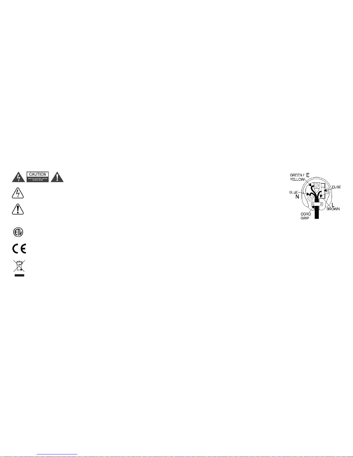
Plug Fitting Instructions (UK only)
The cord supplied with this appliance is factory fitted with a 13A mains plug fitted with a 13A fuse inside. If
it is necessary to change the fuse, it is important that a 13A one is used. If the plug needs to be changed
because it is not suitable for your socket, or becomes damaged, it should be cut off and an appropriate plug
fitted following the wiring instructions below. The plug must then be disposed of safely, as insertion into a
13A socket is likely to cause an electrical hazard. Should it be necessary to fit a 3-pin BS mains plug to the
power cord the wires should be fitted as shown in this diagram. The colours of the wires in the mains lead
of this appliance may not correspond with the coloured markings identifying the terminals in your plug.
Connect them as follows:-
The wire which is coloured BLUE must be connected to the terminal
which is marked with the letter ‘N’ or coloured BLACK.
The wire which is coloured BROWN must be connected to the terminal
which is marked with the letter ‘L’ or coloured RED
The wire which is coloured GREEN/YELLOW must be connected to the
terminal which is marked with the letter ‘E’ or coloured GREEN.
Note - If a 13 Amp (BS 1363) type of plug is used a 13 Amp fuse must
be fitted, either in the plug or adaptor, or on the distribution board.
3011668
Important safety instructions
Page 5

5
Read Instructions - All the safety and operating instructions should be read before the product is
operated.
Retain Instructions - The safety and operating instructions should be retained for future reference.
Heed Warnings - All warnings on the product and the operating instructions should be adhered to.
Follow Instructions - All operating and use instructions should be followed.
Cleaning - Unplug all system components from the wall outlet before cleaning any part of the system. Do
not use liquid cleaners or aerosol cleaners. Use a damp cloth for cleaning.
Attachments - Do not use attachments which are not recommended by Opus Technologies as they may
cause hazards.
Water and Moisture - Do not use this product near water - for example, near a bath tub, wash bowl or
kitchen sink; in a wet basement, or near a swimming pool etc.
Wall or Ceiling Mounting - Speakers should be mounted to a wall or ceiling only as recommended by
the manufacturer. Installers should also ensure that all building regulations are strictly adhered to as cutting
a hole for a loudspeaker may affect the fire rating of a ceiling or wall.
Accessories - Do not place this product on an unstable surface, stand, bracket or table. The product may
fall, causing serious injury to child or adult, and serious damage to the product. Use only a surface,
stand bracket or table recommended by the manufacturer, or sold with the product. Any mounting
of the product should follow the manufacturer's instructions, and should use a mounting accessory
recommended by the manufacturer. A product and stand combination should be moved with care. Quick
stops, excessive force, and uneven surfaces may cause the combination to overturn.
Ventilation - Slots and openings in the cabinets/enclosures are provided for ventilation and to ensure
reliable operation of the product and to protect them from overheating. These openings must not be blocked
or covered. The openings should never be blocked by placing the product on a soft surface. The MCU
should not be placed in a built-in installation such as a bookcase or rack unless proper ventilation is provided
and the manufacturer's instructions have been adhered to. For all components, the manufacturers
instructions on ventilation must be adhered to.
Power Sources - This product should be operated only from the type of power source indicated on the
marking label. If you are not sure of the type of power supply to your home, consult your product dealer or
local power company. For products intended to operate from battery power or other sources, refer to the
operating instructions. This apparatus shall be connected to a mains socket outlet with a protective earthing
connection.
Grounding or Polarization - Do not defeat the safety purpose of the polarized or grounding type plug.
A polarized plug has two blades with one wider than the other. A grounding type plug has two blades and a
third grounding prong. The wide blade or the third prong are provided for your safety. If the provided plug
does not fit into your outlet, consult an electrician for replacement of the obsolete outlet.
Power-Cord Protection- Power supply cords should be routed so that they are not likely to be walked
on or pinched by items placed upon or against them, paying particular attention to cords at plugs,
convenience receptacles, and the point where they exit from the product. The mains plug is used as the
disconnect device and shall remain readily operable.
Protective Attachment Plug - The product is equipped with an attachment plug having overload
protection. This is a safety feature. If replacement of the plug is required, be sure the service technician has
used a replacement plug specified by the manufacturer that has the same overload protection as the original
plug.
Lightning - For added protection for this product during a lightning storm, or when it is left unattended and
unused for long periods of time, unplug it from the wall outlet and disconnect the antenna or cable system.
This will prevent damage to the product due to lightning and power-line surges.
Overloading - Do not overload wall outlets, extension cords, or integral convenience receptacles as this
can result in a risk of fire or electric shock.
Object and Liquid Entry -Never push objects of any kind into this product through openings as they may
touch dangerous voltage points or short-out parts that could result in a fire or electric shock. Never spill
liquid of any kind on the product.
Servicing - Do not attempt to service this product yourself as opening or removing covers may expose you
to dangerous voltage or other hazards. Refer all servicing to an authorised service agent.
Lithium Battery - This product is equipped with a lithium battery that is NOT to be replaced by the user.
CAUTION - Danger of explosion if battery is incorrectly replaced. To be replaced only with the same or
equivalent type by qualified service personnel.
Damage Requiring Service - Unplug this product from the wall outlet and refer servicing to qualified
service personnel under the following conditions:
a) When the power-supply cord or plug is damaged.
b) If liquid has been spilled, or objects have fallen onto the product.
c) If the product has been exposed to rain or water.
d) If the product does not operate normally by following the operating instructions. Adjust only those
controls that are covered by the operating instructions as an improper adjustment of other controls may
result in damage and will often require extensive work by a qualified technician to restore the product to
its normal operation.
e) If the product has been dropped or damaged in any way.
f) When the product exhibits a distinct change in performance - this indicates a need for service.
Replacement Parts - When replacement parts are required, be sure the service technician uses
replacement parts specified by the manufacturer or have the same characteristics as the original part.
Unauthorised substitutions may result in fire, electric shock, or other hazards.
Safety Checks - Upon completion of any service or repairs to this product, ask the service technician to
perform safety checks to determine that the product is in proper operating condition.
Heat - The product should be situated away from heat sources such as radiators, heat registers, stoves, or
other products (including amplifiers) that produce heat.
Important safety instructions
Page 6

6
Opus 500 system component overview
WCU500
Wall Control Unit
Main zone keypad with LCD display, used to select
and control sources connected to the MCU.
WCU300
Wall Control Unit
Sub-zone keypad, used to extend a main zone
into a secondary room.
SRC500
System Remote Control
System remote control for everyday use in
conjunction with the keypad.
LRC500
Learning Remote Control
Learning remote control for controlling source equipment
and teaching infra-red source commands to the MCU.
MCU500
Master Control Unit
Central control unit, which connects to your audio
sources and distributes them to the desired zones.
VSU500
Video Switching Unit
An optional unit which connects to your video sources
and distributes video to desired zones.
Page 7

7
WCU500 general button and specific source functions
Mute
Press to mute the audio
output.
Operation
Use these buttons to
control the source
currently activated.
Volume
Press to adjust zone
volume (also used in
menu options).
Setup
Access and select menu
options.
Source selection
Press to activate the
desired source. Use
Source and Source
to scroll through sources.
The sources selected will
depend on your
installation.
The Tuner is built-in and
always available via the
dedicated button.
FAV-1
Tuner
CD
SAT
DVD
Hard Disk Server
-
Play/Pause CD
-
Play/Pause DVD
Play
-
Stop CD
-
Stop DVD
Stops Hard Disk Server
Standby
Press to set the system to
Standby mode.
Skip to previous radio
wave band
Skip to previous CD
-
Skip to previous DVD
Skip to previous album
Skip to next radio
wave band
Skip to next CD
-
Skip to next DVD
Skip to next album
Skip to previous pre-set
radio station
Skip to previous
CD track
Channel down
Skip to previous
DVD track
Skip to previous track
Skip to next pre-set radio
station
Skip to next
CD track
Channel up
Skip to next
DVD track
Skip to next track
Selects pre-set
radio station
Selects disc 1,
track 1
Select channel
1 on receiver
Selects disc 1,
track 1
Selects album 1,
track 1
Source
Possible source functions (dependent on installation).
Page 8

8
WCU500 display breakdown and button index
Time (24 hr clock)
Volume scale
Sleep active
Alarm beeper active
Alarm active
Shared source indicator.
‘Shared’ indicates that the
selected source is also in
use by another zone.
Selected source
TUNER
Selects Opus tuner.
SOURCE
SOURCE
Source up.
Source down.
LOCAL
Selects local source, where installed (typically a TV or
video located in the same room as the keypad).
Skip CD track or pre-set radio station.
Skip CD or radio wave band.
Play/Pause.
Volume up and down (also used in menu
options).
Mute.
STBY
FAV-1
Selects pre-set radio station, CD etc. Press twice to go
to second pre-set bank (station 11) on Tuner.
Stops current source.
SELECT
Used to select options in set-up mode.
MENU
Used to scroll through options in set-up mode.
Zone shutdown. Press and hold for three
seconds to shutdown all Opus zones.
Page 9

Clock Alarm Sleep Party All On All Off B-light Vol Limit SRC Limit
SELECT
9
To access the Setup menu
press the button.
To adjust the bass use the
and button
To activate special Opus functions or adjust the sound in your zone press the button
MENU
Bass Treble Balance Loud Wide Setup
MENU MENU MENUMENU MENU
MENU
Pressing the Menu button
returns to the Tuner etc.
To adjust the treble use the
and button
To adjust the balance use the
and button
SELECT
Use to toggle the Loud
control on or off.
SELECT
Use to toggle the Wide
control on or off.
SELECT
Press the Menu button to skip to the next option
Press to
select the source and
use and to
toggle on or off
(whether this source
should be available in
this zone).
Press . to
confirm and exit.
MENU
SELECT
MENU MENU MENU MENU MENU MENU MENU
SELECT SELECT SELECT SELECT SELECT SELECT SELECT SELECT
To set the correct time
use and to
adjust the flashing
digits. Press
to move to the next
set of digits. When
done, press
to exit.
1. To set the alarm
time use and
to adjust the
flashing digits.
Press to
move to the next
set of digits. When
done, press.
to confirm the wake
up time.
2. To select a source
press to
toggle between
Beeper and Tuner.
When Beeper is
activated, the
icon is shown on
the display. Press
. to continue.
3. To set the alarm
volume use and
to adjust the
volume scale on
the display. Press
. to continue.
4. Press to
toggle the alarm on
or off. When the
alarm is active, the
Alarm icon is
shown on the
display. Press
. to exit.
1. To set the sleep
timer use and
to adjust the
flashing digits.
Press to
move to the next
set of digits. When
done, press
to confirm the sleep
time.
2. Press to
toggle the sleep
function on or off.
When the sleep
function is active,
the icon is
shown on the
display. Press
. to confirm
and exit.
When sleep mode is
active, the Opus zone
will shutdown at the
preset time.
To activate the Party
mode, press
to toggle between on
and off. When Party
mode is active, all
main zone keypads
will display “Party”.
During Party mode
each keypad will only
have access to the
volume, on and off
controls for that zone.
When you activate
Party mode the
keypad you use will
become the Party
Master Keypad. This
keypad is the only
keypad that can
control the source for
the other zones.
When Party Off is
selected, each zone
has its volume set to
zero. To exit Party
mode, press and hold
. for three
seconds.
To activate the All On
mode, press
to toggle between on
and off. The All On
mode allows all the
zones to play a
source selected from
a single keypad.
Unlike Party mode,
each keypad retains
full control over its
volume and source
controls.
To activate the All Off
mode, press
to toggle between on
and off. Activating All
Off shuts down all
active zones.
To activate the
keypad display
backlight, press
. to toggle
between on and off.
To set a volume limit
for this zone use
and to adjust the
volume (set max
volume output on a
selected zones i.e.
kids bedroom). When
done, press .
to confirm the volume
limit and exit.
Press the Menu button to skip to the next option
Press the SELECT
button to modify a
function
SELECT
MENU
MENU
SELECT
SELECT
MENU
MENU
SELECT
MENU
MENU
SELECT
MENU
SELECT
STBY
SELECT
SELECT
SELECT
SELECT
MENU
SELECT
MENU
Note: If the clock has
problems check the
dip switch on the rear
of your MCU. Even
where RDS station
naming data is
available it is often
recommended that
the ‘RDS CLK’ is
switched to ‘off’ due
to the unreliability of
these transmissions.
To change the name of the current source push
and hold to enter the Source Naming
menu.
Use and to adjust the selected letter. Press
. to move to the next letter. Press
to confirm and exit (or press to exit
without saving changes).
SELECT
SELECT
Source naming
MENU
SELECT
WCU500 main menu functions
Page 10

10
Volume up
Use this button to increase
the volume in your sub
zone (also used to control
Bass/Treble/Balance when
Select button has changed
function).
Standby button
Use this button to set the
system to standby mode.
IR sensor window
Volume down
Use this button to decrease
the volume in your sub zone
(also used to control
Bass/Treble/Balance when
Select button has changed
function).
Select button
Use this button to access
Bass/Treble/Balance. LEDs
will illuminate which mode
you are in:
Volume mode
(Volume level
displayed)
Bass setting mode
Treble setting mode
Balance setting
mode
Fader setting mode
WCU300 keypad f unctions
Page 11

11
MCU500 operational buttons
Power switch
Note: In normal operation you do not
need to power off the Opus system with
this switch. Simply use the Standby
buttons on each keypad.
Cloning port
Transferring IR commands from LRC500
(used by installer only).
Zone active
LED lit to indicate current active zones.
IR indicator
LED flashes to indicate IR transmissions
for each zone.
Tuner buttons
Tunes tuner/preset buttons
(used for setup only).
Store
To store tuner presets
(used for setup only).
Mode
Selects preset or search mode
(used for setup only).
Setting the tuner presets
This is done via the buttons on the MCU’s front panel. 29 FM, 7 AM/MW and 7 LW presets are available.
Step 1 - Put the tuner into scan mode by pressing the Mode button.
Step 2 - Use the and buttons to find the station you wish to store.
Step 3 - Press the Store button and the tuner will automatically display the next available preset number.
Step 4 - To store the station in this location press store. You can store the station in a different location by
using the and buttons to select a new location and then press store.
Step 5 - If you wish to store presets in another waveband (FM, AM/MW or LW) press the Band button to
select a new waveband and repeat step 4.
Step 6 - Once you have stored your presets press Mode. This puts the tuner back into preset mode. In the
preset mode the and buttons on the keypad skip up and down through the presets.
Erasing tuner presets
Erasing tuner presets - Only works with MCU500 Software version v2.3 or higher (to update your MCU
software to the latest version, contact your dealer who will arrange this for a charge).
Step 1 - Power down the MCU.
Step 2 - Hold down the ‘Store’ and ‘Mode’ buttons the front of the MCU.
Step 3 - Power up the MCU whilst still pressing buttons.
Step 4 - The tuner LCD display will stay blank.
Step 5 - Release the buttons and the tuner LCD will return to normal.
Step 6 - The presets will now be erased, start storing new presets from preset 1.
Note - The tuner only skips through presets that have been set. If only four presets are set the tuner will skip
1-2-3-4-1-2-3-4 and so on. If no presets are set or only one is set the tuner will not skip at all.
MODE
STORE
BAND
POWER
CLONING PORT
ZONE ACTIVE
Page 12

12
IMPORTANT!
This MCU500 should only be programmed using
LRC500 V2.5 (or higher).
Earlier versions of LRC500 are not compatible and
must not be used.
Installing IR codes for your new
source
First teach the LRC500 learning remote control the
IR commands for your new source. See the LRC500
manual for further details.
Next use the cloning operation to download the new
codes to the MCU500. To perform this connect the
LRC500 to the MCU via the mini-jack to mini-DIN
cloning cable. The IR indicator on the MCU will
illuminate showing cloning is active.
Press the TRANSMIT button on the LRC500 for three
seconds. You will hear a beep and the transmit mode
screen will appear.
Press each flashing number in order until they have
disappeared. The device screen displays the ‘Tx’
icon.
(If the LRC500 is version 1 you will need to press the
LRC500’s button to start the transmitting
operation.)
The LRC500 ‘Tx’ icon and the MCU’s IR indicator will
flash.
When the data is transfered the ‘Tx’ icon will stop
flashing.
Exit the transmit mode by pressing the LEARN
button.
Current pre-set
from bank
FM stereo
Digital tuner wave
band display
Current source display
Signal level
Note: Full 10 bars are required
for optimal quality reception
Stereo sound
MCU500 LCD display
LRC500 programming
Page 13

13
Opus Technologies warrants this product to be free from defects in materials and workmanship (subject to
the terms set forth below). Opus Technologies will repair or replace (at Opus Technologies’ option) this
product or any defective parts in this product. Warranty periods may vary from country to country. If in doubt
consult your dealer and ensure that you retain proof of purchase.
To obtain warranty service, please contact the Opus Technologies authorised dealer from which you
purchased this product. If your dealer is not equipped to perform the repair of your Opus Technologies
product, it can be returned by your dealer to Opus T echnologies or an authorised Opus Technologies service
agent. You will need to ship this product in either its original packaging or packaging affording an equal
degree of protection.
Proof of purchase in the form of a bill of sale or receipted invoice, which is evidence that this product is
within the warranty period, must be presented to obtain warranty service.
This Warranty is invalid if (a) the factory-applied serial number has been altered or removed from this product
or (b) this product was not purchased from an Opus Technologies authorised dealer. You may call Opus
Technologies or your local country Opus Technologies distributor to confirm that you have an unaltered serial
number and/or you purchased from a Opus Technologies authorised dealer.
This Warranty does not cover cosmetic damage or damage due to acts of God, accident, misuse, abuse,
negligence, commercial use, or modification of, or to any part of, the product. This Warranty does not cover
damage due to improper operation, maintenance or installation, or attempted repair by anyone other than
Opus Technologies or an Opus Technologies dealer, or authorised service agent which is authorised to do
Opus Technologies warranty work. Any unauthorised repairs will void this Warranty. This Warranty does not
cover products sold AS IS or WITH ALL FAULTS.
REPAIRS OR REPLACEMENTS AS PROVIDED UNDER THIS WARRANTY ARE THE EXCLUSIVE REMEDY
OF THE CONSUMER. OPUS SHALL NOT BE LIABLE FOR ANY INCIDENTAL OR CONSEQUENTIAL
DAMAGES FOR BREACH OF ANY EXPRESS OR IMPLIED WARRANTY IN THIS PRODUCT. EXCEPT TO
THE EXTENT PROHIBITED BY LAW, THIS WARRANTY IS EXCLUSIVE AND IN LIEU OF ALL OTHER
EXPRESS AND IMPLIED WARRANTIES WHATSOEVER INCLUDING, BUT NOT LIMITED TO, THE
WARRANTY OF MERCHANTABILITY AND FITNESS FOR A PRACTICAL PURPOSE.
Some countries and US states do not allow the exclusion or limitation of incidental or consequential
damages or implied warranties so the above exclusions may not apply to you. This Warranty gives you
specific legal rights, and you may have other statutory rights, which vary from state to state or country to
country.
Limited warranty
Page 14

This guide is designed to make using the Opus System as easy as possible.
Information in this document has been carefully checked for accuracy; however, no guarantee is given to
the correctness of the contents. The information in this document is subject to change without notice.
If you notice any errors please feel free to email us at:
info@opus-technologies.co.uk
Copyright
© Copyright Opus Technologies Ltd 2007
This document contains proprietary information protected by copyright.
All rights are reserved.
No part of this manual may be reproduced by any mechanical, electronic or other means, in any form, without
prior written permission of the manufacturer.
Trademarks
All trademarks and registered trademarks are the property of their respective owners.
www.opus.eu
Opus is committed to providing the highest levels of service and support.
For full details of this product visit the Opus website:
Made from recyclable material
Part No. AP14088/2
 Loading...