

Page 1
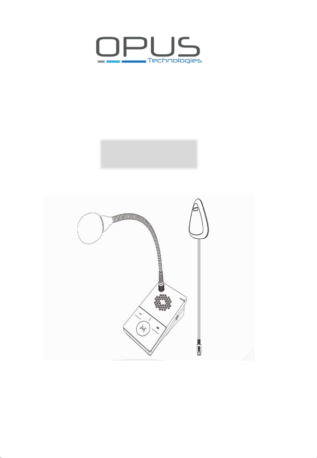
Digital Window Intercom
User Guide
2018
OP-6505B
1
Page 2

2
Page 3

Summary…………………………………………………………………………………………….……. 3
Safety precautions………………………………………………………………………………………… 4
Product introduction……………………………………………………………………………………. 5
Features………………………………………………………………………………………………….…… 5
Hardware interface instruction……………………………………………………………….…… 6
Packing list……………………………………………………………………………………….………….. 7
Wiring………………………………………………………………….………………………….…….…….. 8
Basic function……………………………………………………………………………………….……… 9
Local intercom……………………………………………………………………………….………….…. 9
Remote intercom………………………………………………………………………….……………… 9
Scene mode adjustment…………………………………………………………….………………… 9
Recording…………………………………………………..………………………………….…………….. 10
Fault exclude………………………………………………………………………………………………… 10
DCL20-65……………………………………………………………………..…………………………… 11
Purpose………………………………………………………………………………………………………… 11
Targeted audience……………………………………………………………………….…….………… 11
Alert……………………………………………………………………………………………….….….…….. 11
Icons………………………………………………………………………………..…………………..……… 11
Icons et note………………………………………………………………………………………………… 11
Attention, warning and danger icons……………………………………………..……………. 11
Conversion tables…………………………………………………………………………………….…… 12
Description………………………………………………………………………….………….….………… 12
The range……………………………………………………………………………………………………… 12
Contents………………………………………………………………………………………….…………… 13
Safey note……………………………………………………………..……….……………….…………… 13
Installation…………………………………………………………………………………..………………. 14
Connections and settings……………………………………………………………………………… 16
Explication………………………………………………………………………………………….………… 17
Specifications……………………………………………………………………………………………….. 18
Contents
3
Page 4

Summary
Warning and Reminding
This symbol means there are potential safe troubles, it may cause death or
serious injury with incorrect operation.
This symbol used to remind the user that this device attached the important
operation and maintenance instructions.
Setting and Installation
• Avoid wet by water.
Do not put the machine to be exposed to rain water or other liquid stained environment,
otherwise it may lead to fire or get an electric shock.
• Do not use the other power voltage.
Using the device marked voltage to connect it.
It may lead to fire or electric shock if using the higher voltage.
• Do not scratch the power cord.
Don’t scratch, cut or twist the power cord.
Please keep the power line far away from the heated object and do not put heavy things on it,
otherwise it may lead to fires or electric shock.
Using machine
• In case of the anomalies appears.
Please shut off the power supply immediately when finding the following abnormal phenomena
within using, please contact with supplier. It may cause fires or electric shock if it`s still using it.
When the device with smoking or strange flavor.
The device internal is invaded by water or other things. Device fall off or device shell is damaged.
The power cord is damaged (wire core is exposed or broken etc). Device fault (it can`t connect
network, no sound etc.).
• Do not open the device internal or modify the device Don`t make other things
invaded to the device internal.
Don’t make the metal items or inflammable objects inserting to device internal, otherwise it will
cause fires or electric shock.
• Do not touch when lightning
To avoid electric shock, please do not touch the device and the plug while lightning.
• Do not put the liquid container or metal object on the device
If the container is fall down and make the liquid permeate into the device, it will cause fire or
electric shock.
• Do not open the device internal or modify the device
The device internal contains high voltage parts, once open the cover or modify the device, it may
cause fires or cause shock.
All about device maintenance and modification should be operated by professional personnel.
•The notice for maintenance or long time without using
Please shut down the power and pull out the power line while maintenance or the device won`t
be used for 10 days or more.
It may cause electric shock or fires if do not make it.
4
Page 5
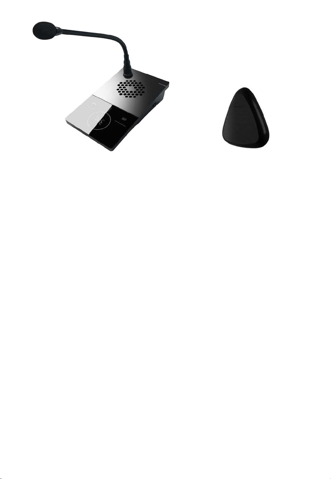
Internal window intercom Internal window intercom
Features
• Adopt single DSP multi-channel language auto-control technology, avoiding squeaking and
disturb to realize real digital full-duplex intercom.
• Adopt full touchable transparent key design, keep intercom without disturb from key-click
and keep it with the halo light on.
• Recognizing sound source, control environment noise, automatically adjust volume and
restore the original sound.
• Providing three mode scene (quiet, standard, noisy), support one-key adjustment.
• Wiring external and internal intercom adopt one line to connect the desk, better solving
the loosen caused by moving and keeping the desk more clear and beautiful.
• Professional cavity structure design, adopting hard metal cavity to prevent machine
resonance, purify and naturalize the sound to transparent.
• Personalized and customized service language, manual broadcasting “Hello, welcome”,
“Thank you welcome for next time coming”
• Support double recording mode and providing the recording output to HD recording host
and DVR to process the third-party recording storage.
• LED distinguished show the real state of internal window intercom.
Coordinate HD recording host function:
• Realizing remote calling and receive calling, hands-free intercom with central microphone.
• Remote central microphone can real-time monitoring window intercoms.
• Receiving remote one-way network broadcasting.
• Internal window intercom can make real-time recording by the record key and it will be
stored on the HD recording host.
• Remote upgrading the firmware of window intercom in the HD recording host web page.
5
Page 6
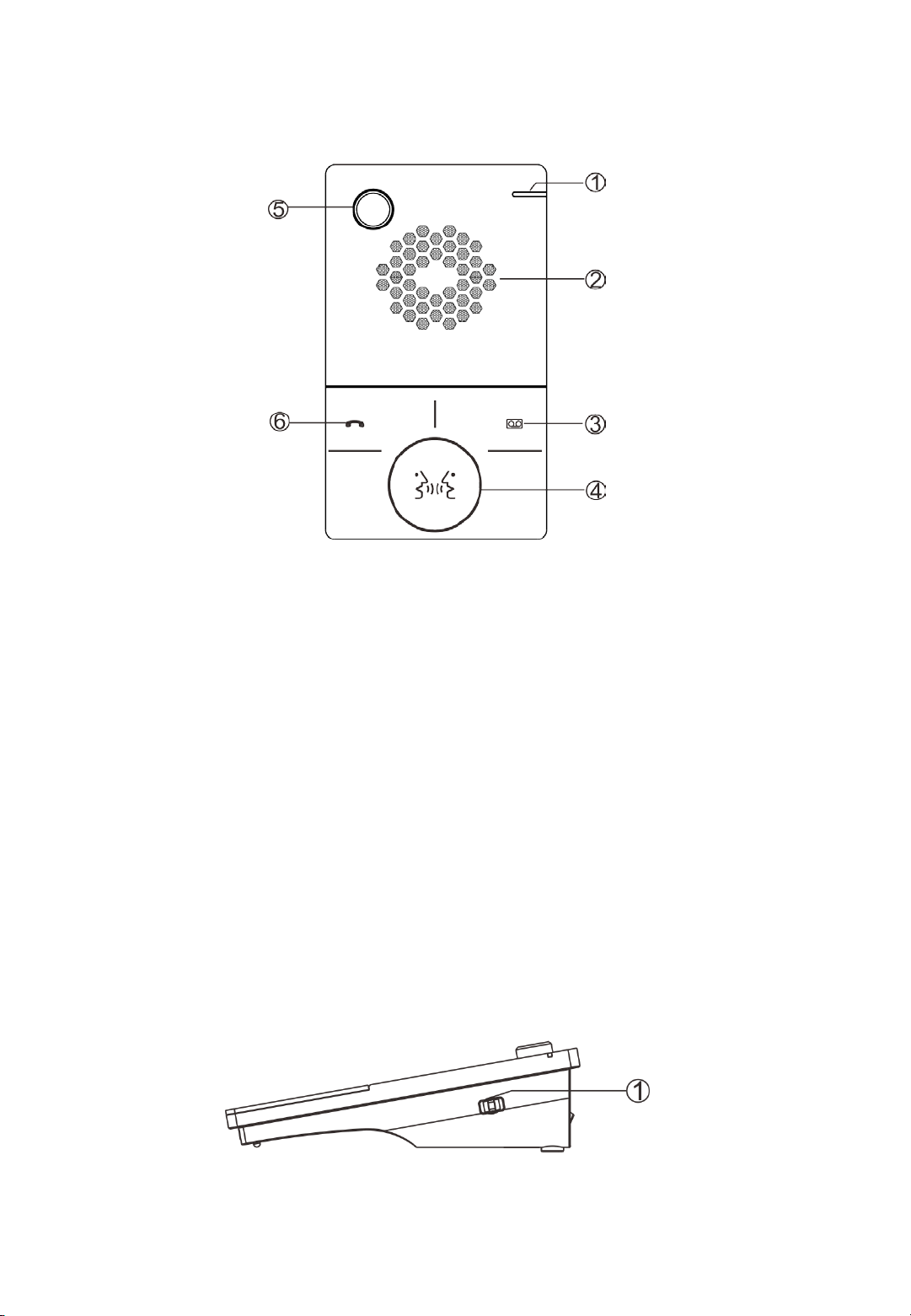
Hardware interface instruction
Internal window intercom
【Front view】
①Working indication light: red light is offline, green light is online
②Loudspeaker: amplify the local intercom audio.
③Recording key: make a recording when press the key at the first time, finish the recording
by press again, the recording key will quickly red flashed in the recording process.
④Intercom key: press the key to intercom with external window intercom, finish the
intercom by press again, the green intercom key will be light on.
⑤Microphone pole socket: plug the microphone pole, collecting local intercom audio.
⑥Voice broadcasting key remote intercom key:
Voice broadcasting: Press voice broadcast key to automatic play voice prompt in the process
of intercom with window external terminal, press shortly to prompt "Hello, welcome", long
press for a while to prompt "Thank you, welcome to come next time.". The broadcasting key
green flashed during the process of broadcasting.
Remote intercom: coordinate with HD recording host to use, click this key to call named
terminal by server in the online condition.
【Side view】
①Scene mode regulating switch:3 scene mode adjustment 【noisy(1)、standard(2)
、quiet(3)】, defaulted as standard mode.
【connection wiring】
6
Page 7

①Power interface: connect with DC12/2A power.
②Communication interface:connect with the network HD recording host.
③Analog audio input interface: output analog audio, connect with DVR or camera.
④External window intercom interface.
【External window intercom】
①Loudspeaker/MIC:
Loudspeaker:amplify the local intercom audio; MIC:pick up the local intercom audio;
②Internal window intercom interface
Packing list
Window intercom system include following accessories, please check following parts, please
contact with distributor if any parts are missing.
(1) Internal window intercom 1 set
(2) External window intercom 1 set
7
Page 8

(1) Microphone pole 1 pcs
(2) Power adapter 1 pcs
(3) Wiring harness (3*100mm)3 pcs
(4) Cable clamp (HC-100) 3 pcs
(5) Wiring connector (3.81-2P) 1 pcs
(6) Quick installation manual 1 pcs
Wiring
(1) Connect the one port of power adapter to the power interface of internal
window intercom, the other port connect with power socket.
(2) Connect interface of external window intercom with internal window
intercom.
(3) Connect the one port of Ethernet to internal window communication
interface and the other port connect to HD recording host (only suitable for online
environment).
8
Page 9

Basic function
Local intercom
After connected internal window intercom and external window intercom, then power-on.
Press the intercom key of internal window intercom, it can digital full duplex HD intercom with
external window intercom, press again to stop intercom.
Remote intercom
Used with HD recording host, under the online status, press remote intercom key to call the
server pointed terminal.
Scene mode adjustment
Window intercom provides three scene modes: Noisy (1), Standard (2), Quiet (3) 】; the
default mode is standard mode.
Incoming prompt tone:
Press voice broadcast key to automatic play voice prompt in the process of intercom with
window external terminal, press shortly to prompt "Hello, welcome", long press for a while to
prompt "Thank you, welcome to come next time.". To finish the audio note broadcast by long
press this key or click other keys.
9
Page 10

Fault exclude
Why the terminal can not talk with others?
1. To realized talking with other terminals, it must be through HD recording
host. Check whether connect with HD recording host.
2. Check server mapping settings is right or not.
Why recording host can not login to the server?
1. Check whether connect with HD recording host.
2. Check the software server and the main controller is normal opened or
not. It is required to close all firewall before open the software server (including system
built-in firewall and other antivirus software firewall).
3. Check the terminal network cable and switcher whether work normal,
damaged, and disconnect or not etc;
4. Check the HD record host settings, please check the terminal ID...etc
parameters.
10
Recording
Analog recording
Window internal intercom can output analog audio, and it is ok for connect with the DVR to
make auto-recording.
Network recording
When the window intercom system is online, window intercom system will automatic
deliver digital recording data during intercom to realize 24 hours recording. If press the
recording key, it can trigger HD record host to make event recording ,when press again the
record can be finished.
HD recording host can check and play the recording, relevant operation please refer to the
manual of “HD recording host”
Page 11

DCL20-65
Purpose
The OP65-05B includes a DCL20 loop amplifier that makes reception accessible for people with
hearing loss. The Installation and Operation Manual provides the information you need to install,
configure, and use a DLC20-65 kit. The Installation and Operation Manual provides the necessary
information for installing,configuring and using an DCL20-65.
Targetedaudience
The Installation and Operation Manual is intended for installers and users of the DCL20-65.
Alerts
This manual discusses four types ofalerts. The type of alert is closely related to the effect that
may occur if the alert is not observed.
These alerts, ranked in ascending order of severity, are the following:
• Note
Additional information. Generally, the non-observance of a Note type alert does notresult in
any material or bodilyinjury.
• Attention
Failure to observe a caution alert may resultin propertydamage.
• Warning
Non-compliance with a type alert Warning may result in serious personal injury and property
damage.
• Danger
Failure to observe a danger alert may resultin death.
Icons
Icons andnotes
Icons used with notes provide additional
informationaboutit. See thefollowing
examples:
Attention, warning and danger icons
The icons used in combination with Attention,
Warning and Danger indicate the type of risk
present. See the followingexamples:
Note:
General icon of notes
Note:
Symbol referring to thesource
indicatedinformation.
Attention, warning,danger:
Electrocution riskicon.
Attention, warning,danger:
the general icon of precautionary
state- ments,
Attention, warning,danger:
Electrostatic discharge riskicon.
11
Page 12

Conversion tables
In this manual, SI units are used to expresslengths, masses, temperatures etc.
These can be converted to non-metric units using the followinginformation.
Table 1: lenght units conversion
Table 2: Mass unitsconversion
Table 3: Pressure unitsconversion
Table 4: temperature unitsconversion
25,40 mm = 25,4 mm
1 mm =
1,00000
25,40
mm = 2,54 cm
1 cm = 0,3937
po
30,48 cm = 0,3048m
1 m = 3,281 pd
1 ml = 1,609
km
1 km = 0,622
ml
1 lb = 0,4536
kg
1 kg = 2,2046
lb
1 psi = 68,95
hPa
1 hPa = 0,0145
psi
Note:
1 hPa = 1mbar
°
F = 9 /5. ( ° C +32°C = 5 /9. ( ° F32)
12
Description
The DLC20-65 kit is the ideal equipment for counters or reception desks allowing audio accessibi
lity for people with hearing loss. This product is for all Public-facing establishment. It has the
advantage of being one of the most compact and discreet of the market allowing optimal
integrationresults. It offers especially a perennialinstallation.
Therange
We are pleased to introduce our new brand Opus Technologies designed and manufactured in
France. We propose innovative products offering maximum comfort for theusers.
Page 13

DCL20-65
The DCL20-65 is an induction loop kit that can be used to equip counters or reception desks.
The system allows to meet the restrictions of the law of european equal treatment directives
while respecting the requirements of EN60118-4. The set is designed to offer accessibility to
hearing- impairedequipped with a T-position on their hearing aid.
The amplifier is designed to be discreetly attached under a desk or counter. It is equipped with
two inputs, settings and LEDs indicating the presence of power supply and loopcurrent.
The device incorporates an audio processing to have an automatic control of the sound levels,
avoidingloud and suddennoises.
Safetynotes
The majority of problems with the hearing loop loop happens when the installation has not
been properly reflected so let's take a while before starting the installation to better results and
time saving.
Ideally, the loop amplifier should be placed near the area to be covered. This may involve
placing the amplifier on a panel,under a desk or under a table.
The pickupmicrophone should be as close as possible to the inputof theamplifier.
To position the loop in the space to be equipped, it is important to take into account the final
users of thesystem.
For example, if the place is planned for a con- versation between a speaker and a client, a loop
around the desk may be a better solution rather than a loop around the perimeter of the
room. It will limit radiation and increase confidentiality.
13
Contents
This kit includes:
A DLC20 amplifier
A power supply
A power cord
A 1,80m loop cable
Three 2-point connectors
One 3-pointconnectors
A set of 2 stickers « space adaptedfor hearing impaired».
Page 14

Installation
Composition and assembly ofthe loop
The loop consists on the following 3 elements: a loop cable, a loop adapter and a connecting
cable.
The loop is ready but it is possible to disas- semble it to adapt it to the reception desk. See
below.
To disassemble the loop that will equip the counter, first unscrew the support of the elec- tronic
card.
Connect the beginning and the end of theloop cable to the circuit board (red connector).
Then plug the 50-70 cm connecting cable sup- plied to the "amplifier" connector of the adap- ter
and to the "Loop" terminal block of the am- plifier.
Your loop is now created andconnected.
Installation of the loop in the counter
1. There are 2 possibilities to place a loop in
a counter as described below, however we
strongly advise you to use the first
version:Place the loop on the vertical and
horizontal portion of the counter as shown
in figure 1. This type of installation ensures
bettercoverage in frontof the counter.
Figure1.
Note:
The wire supplied in the DLC20-65kit ensures the quick installation of a magnetic
loop system in a reception desk, counter or cashdesk.
In order to optimize the radiation of the magnetic field and to guarantee a
. better result he wire should be placed close to the customer.
Loop
amplifier
14
Page 15

2.Position the loop on the horizontal counter-
top by positionning the cable closest to the
customer.
3.Install the loop on the vertical countertop by
positioning the cable closest to thecustomer.
Set the loop using the binding clips supplied for this purpose. For better durability, it may be appropriate to install the loop in a plasticchute.
Then connect the connecting cable to the termi- nal block "amplifier" of the connector on the
terminal block "loop" of theamplifier.
Screw the connector on the cross.
Attention, warning, danger:
The loop must not be positioned
under a metal structure. The magnetic field would be absorbed by the
metal mass and would not equip
the counter properly. Thereare
other solutions for installing a loop in ametal
counter (see figure3)
For greater coverage around the counter, it is possible to install a cable on the floor. The loop can
be placed in the slab (over the wire mesh), under a coating (parquet, carpet, ... etc) using a
copper tape or glued under a carpet as shown in figure 3.
Figure3.
The wire supplied in the DCL20-K kit produces a
magnetic field radiating on a perimeter of 1.2m
which allows a people to receive the signal
com- fortably.
Figure4.
amplifier
The pictogram with an integrated loop can be
fixed on the desk and turned to the customer’s
side to avoid disturbances due to metal (see
Figure 4). Loop amplifier
Loop1
Loop2
Loop
amplifier
15
Figure 2.
Page 16

Connections andsettings
Audioconnection
To connect the supplied microphone with the kit, insert the 3.5 jack intothe microphone input 1.
Connecting to an intercom or specific source: Connect your source to input 2 of the DCL20. This
input supports the following sources: line, low impedance and 100V with anadapter.
Micro input1:
Type : Jack3,5
Feature: phantom power
Input ligne 1:
Type: TerminalBlock
Input type: Line or microphone, screwconnec- tion.
Input 2:
Type: TerminalBlock
Input type: Line /low impedance/ 100V withan
adapter.
micro / Ligne / Mass
Ligne / Mass
Jack3,5
16
Page 17

Explication
The wire forming the loop are connected to an audio amplifier. The hearing aid often called "T" or
"T-coil" which is placed inside spirale wire. The magnetic field generated by the large loop will
cross the coil and, by the induction process, the electrical signal present in the large loop will be
found in the one small. The signal of the audio amplifier is transmitted to the hearing aids, which
will thenrestore it to the ear of the impairedones.
The loop can be installed in the floor or at the roof level, more precisely between 1.10m and
2.20m from the listeningheight(ears).
The presence of an hearing loop is often indi- cated by a blue logo representing a crossed out ear
and a letter T. Generally, a hearing aid has two major positions, the M and the T. The position M
makes it possible to perceive the sound thanks to sound pressure as a microphone, while the
position T (T for telephone) directly receives the audio signals transmitted by induction via the
integrated coil. Some aids combine these two modes of operation with the MT position. It allows
the hearing impaired to perceive both ambient noise and inductively transmitted signals.
17
Loop and powerconnection
Connect the loop cable to the"Loop"inputon theDCL20.
Power supply:Connectthe power supplyfrom the kit to the "Power supply"input.
Note:
Loop input does not impose any
. sense of connection
AC / DCconnector 5
x 2,1mm
Page 18

Specifications
Inputs
Audio
inputs
2 (1 microphone
orline input and
1 lineinput)
Type
Micro Jack 3.5,
Phoenix terminal
block
Phantom
4,5V 1mA
Power
supply
Characteristics
12V DC 1,5A
Type
Separate power box
Voltage
230V 50/60 Hz
Power
20W max
Fuse
Thermal
Audio
Processor
Compressor
Variable 1: 1 to 20:1
Attack
10mS
Descent
Automatic
500mSou
1500mS
Noise
reduction
Bandwidth Limits for
8 KHz at Total Gain,
16KHz to -6dB
Dynamic
> 60dB
THD
THD+N<0,5% à 1KHz
Output
Type
Current
Loop
resistance 0,5 Ohm à 1Ohm
Peak
current 4A
Current
RMS 2A à 1 KHz
Protection
Thermal, short
circuitand start
Dimensions
andweight (inmm)
DCL20
92 x 52 x 18 (L x H x
P)
Packaging
190 x 190 x50
Weight
0.350g
18
Page 19

Notes:
19
Page 20

Tél : 09.81.24.00.06
Mail: contact@opus-technologies.fr
Opus Technologies — ZI Lagrange II — 9 Chemin de la Vieille Ferme — 33650 MARTILLAC
20
 Loading...