

Page 1

User Guide
La version française de ce manuel est disponible sur le site www.opus-technologies.co.uk/manuals
Eine deutsche Version der Bedienungsanleitung ist verfügbar unter: www.opus-technologies.co.uk/manuals
La versión en español de este manual está disponible en www.opus-technologies.co.uk/manuals
La versione in lingua italiana di questo manuale è disponibile sul sito www.opus-technologies.co.uk/manuals
Een nederlandse versie van deze gebruiksaanwijzing is beschikbaar via www.opus-technologies.co.uk/manuals
Page 2
2
Contents
Installers details 3
Overview
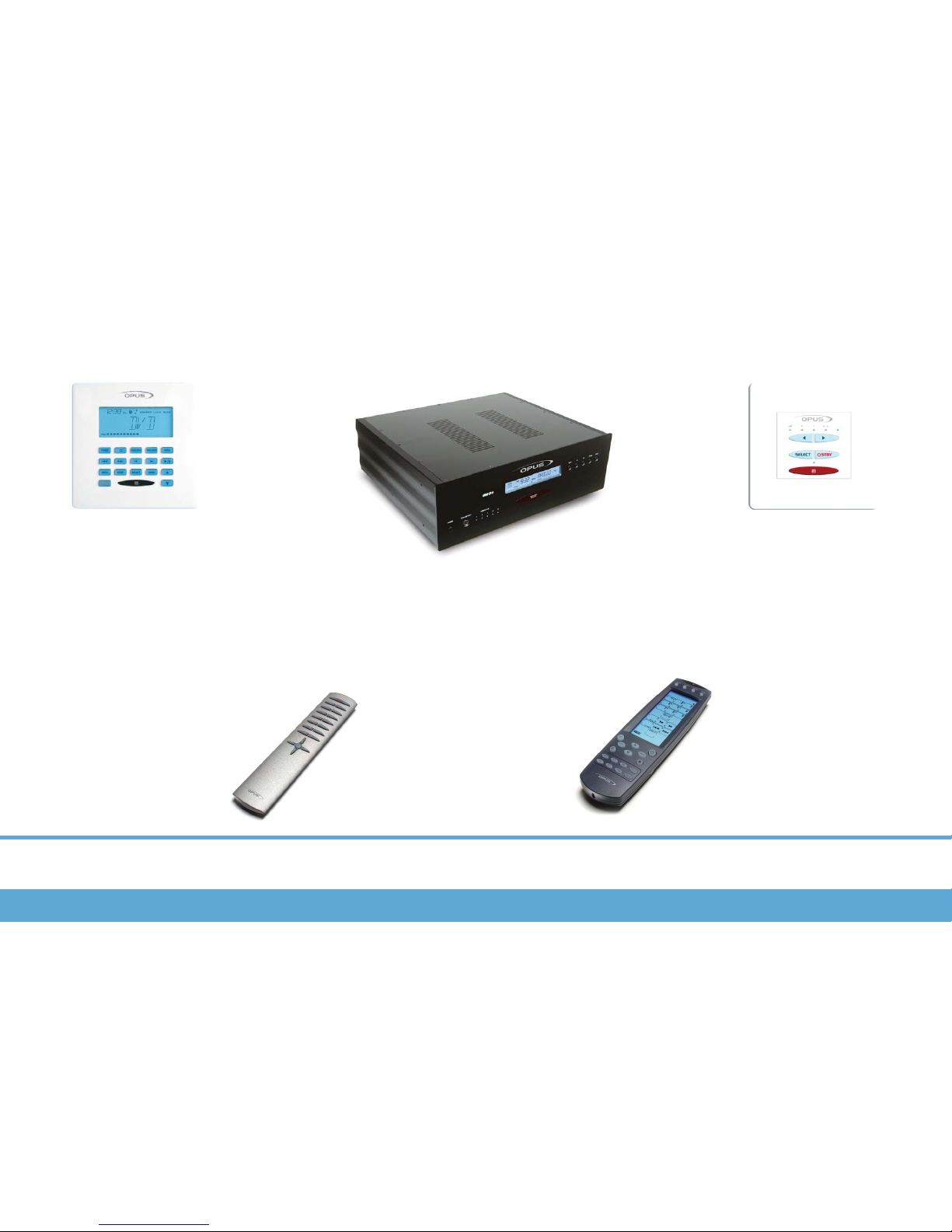
System Components 4
Wall Control Unit WCU500 4
Wall Control Unit WCU300 4
Learning Remote Control LRC 4
System Remote Control SRC 4
Master Control Unit MCU500 4
WCU500
General button functions 5
Key Index and display 6
Menu functions 7
WCU300
Keypad functions 8
MCU500
Detailed buttons 9
Setting the Tuner Presets 9
MCU Display 9
AV1/AV2 Naming 10
Adding additional source equipment 10
LRC500
Programming 12
Specifications 13
Notes 14-15
IMPORTANT
The Opus system offers several variations depending on the the type of
installation. Your installer will fill out the applicable tick boxes, which will
determine which variation is appropriate to your
installation.
Page 3

3
Contents
Installation Details
Opus MCU500 Serial Number:
TO BE COMPLETED BY THE INSTALLER
Installers Details:
(Use separate sheet if required)
Installers contact name:
Installers contact tel no:
Zone/Room Details:
A
B
C
D
Sub zones
3
Source Equipment Details:
CD:
DVD:
SAT:
AV1:
AV2:
(Insert name of equipment connected to this input)
Page 4
4
Overview
System Components
Wall Control Unit
(WCU500)
Main zone keypad with LCD dis-
play, used to select and control
sources connected to the MCU
Wall Control Unit
(WCU300)
Sub zone keypad used to select and
control sources connected to the MCU
Note: A WCU300 can only listen to same source
as the main zone to which it is connected.
Master Control Unit (MCU500)
Central control unit, which connects to your
audio/visual sources and distributes them to
the desired zone.
Learning Remote
Control (LRC500)
Learning remote control for con-
trolling source equipment and
teaching Infra-red source com-
mands to the MCU
System Remote Control
(SRC500)
System remote control for everyday
use in conjunction with the keypad
Opus 500 system component overview
Page 5

5
WCU500
General Button Functions
Source Selection Keys
Press one of these keys to activate
the desired source
Operation Keys
Use these keys to control the
source currently activated
Volume
Use these keys adjust zone volume
Source
TUNER
CD
HARD DISK SERVER
SAT
DVD
Stand-by key
Use this key to set the system to
stand-by mode
Skip to previous pre-
set radio station
FAV-1
Selects pre-set radio
station
STOP
Stops CD
Skip to previous radio
wave band
Play/Pause CD
Set-up keys
Access and select menu options
Skip to next radio
wave band
Skip to previous CD
Skip to next CD
Skip to next pre-set
radio station
Skip to previous CD
track
Skip to next CD track
* Press twice in succession to go to preset 11 in pre-set bank
*
Selects album1
track1
Play
Stops Hard drive
server
Skip to previous
Album
Skip to next Album
Skip to previous track
Skip to next track
Selects disc1 track1
_
_
_
_
Channel down
Channel up
Selects channel1 on
receiver
Stops DVD
Play/Pause DVD
Skip to previous DVD
Skip to next DVD
Skip to previous DVD
track
Skip to next DVD
track
Selects disc1 track1
External source controls may vary. Please contact your installer for further information.
_
_
General Button and specific source functions of the WCU500
Page 6

6
WCU500
Key Index and Display
TUNER
STBY
Selects Opus tuner
Skip CD track or pre-set radio station
CD
CD selector
DVD/AV1
DVD selector. Press and hold for AV1*
SAT/AV2
Satellite TV selector. Press and hold for AV2*
FAV-1
Selects pre-set radio station, CD etc.
Press twice to go to second pre-set bank
STOP
Stops current source
SELECT
Used to select options in set-up mode
MENU
Used to select options in set-up mode
Zone shutdown. Press and hold for three seconds to shutdown all Opus zones
LOCAL
Selects local source (typically a TV or video
located in the same room as the keypad)
Skip CD or radio wave band
Play/Pause.
* When Opus is installed AV1 and AV2 can be renamed to
show the name of the source equipment.
Volume up and down
Shared source indicator.
‘Shared’ indicates that the selected source is also in use
by another zone.
Time
{24 hr clock).
Volume scale.
Selected
Source.
Loud function
active.
Wide function
active.
Sleep
active.
Alarm
Beeper
active.
Alarm
active.
Key Index
WCU500 Display Breakdown and Key Index
Page 7

7
WCU500
Menu Functions
STBY
To activate special Opus functions or adjust the sound in your zone press the key
Bass Treb Balance Loud Wide Set-up
To adjust the Bass use the
and keys.
To adjust the Treble use
the and keys.
To adjust the Balance use
the and keys.
Use to toggle the
Loud control on or off.
The icon will be shown
when Loud is activated.
Use to toggle the
Wide control on or off.
The icon will be shown
when Wide is activated.
To access the set-up menu
press the key.
Clock Alarm Sleep Party All On All off B-Light
MENU
MENU
MENU MENU MENU MENU MENU MENU
MENU MENU MENU MENU MENU
Press the MENU key to skip to the next option
Press the MENU key to skip to the next option
Press the SELECT button to
modify a function
Pressing the menu button
returns to the Tuner etc.
SELECT SELECT
SELECT
MENU
SELECT SELECT SELECT SELECT SELECT SELECT SELECT
MENU
MENU
MENU
MENU
MENU
MENU
SELECT
SELECT
SELECT
SELECT
SELECT
SELECT SELECT
SELECT
MENU
SELECT
SELECT
Setting the time
To set the correct time
use the and
keys to adjust the
flashing digits. Use the
key to move to
the next set of digits.
When you’re done press
to exit.
Setting the Alarm
Setting the alarm wake
up time
Set the alarm time using
the and
keys. Use the key
to move to the next set
of digits. Press to
confirm the wake up time.
Select a source
Press to toggle
between Beeper and
Tuner. When Beeper is
selected the icon is
shown on the display.
Press to continue.
Set the wake up volume
Use the and
keys to set the
volume. The volume scale
is shown on the keypad
display. Press to
continue.
Activating the alarm
Use the to toggle
the alarm on or off. When
the alarm is active the
icon is shown. Press
to exit.
Setting sleep time
Setting the sleep timer
To set the sleep timer
use the and
keys to adjust the
flashing digits. Use the
key to move to
the next set of digits.
Press to confirm
the sleep time.
Activating the sleep
function
Press to toggle
between on and off. The
icon is shown on the
display when sleep is set
to on. Press to
confirm and exit.
When sleep mode is
active Opus will shutdown
the zone at a pre-set time.
Using Party Mode
Activating Party mode
Press to toggle
the Party mode on and
off. When Party mode is
active all zones and sub
zone keypads will display
Party. During Party mode
each keypad will only
have access to the volume, on and off controls
for that zone. When you
activate party mode the
keypad you use will
become the Party
Master Keypad. The
Party Master is the only
keypad that can control
the source for the other
zones. When Party Off is
selected each zone has
its volume set to zero.
To exit Party mode
Press and hold the
key for three sec-
onds to exit Party mode.
Using All On
Activating All On mode
To activate the All On
mode press the
key to toggle between on
and off.
The All On mode allows
all the zones to play a
source selected from a
single keypad. Unlike
Party mode each keypad
retains full control over
its volume and source
controls.
Using All Off
Activating All Off mode
To activate the All Off
mode press the to
toggle between on and off.
Activating All Off shuts
down all active zones.
Setting Backlight
Activating Backlight
To activate the keypad
display backlight use the
key to toggle
between the two options.
Note: If the clock has
problems check the dip
switch on the rear of
your MCU. Even where
RDS station naming data
is available it is often recommended that the
‘RDS CLK’ is switched to
‘off’ due to the unreliability of these transmissions. See page 11 for
instructions.
Page 8

8
WCU300
Keypad Functions
Stand-by key
Use this key to set the system to
stand-by mode
Select key
Use this key to access
Bass/Treble/Balance. LEDs will illu-
minate which mode you are in:-
Volume Down
Use this key to decrease the volume in
your sub zone (also used to control
Bass/Treble/Balance when ‘select’ key
has changed function)
Volume Up
Use this key to increase the volume in
your sub zone (also used to control
Bass/Treble/Balance when ‘select’ key
has changed function)
IR Sensor window
Interface breakdown for the WCU300
= Volume Mode (Volume level displayed)
= Bass Setting Mode
= Treble Setting Mode
= Balance Setting Mode
Page 9

9
MCU500
Detailed Buttons and Setting the Tuner Presets
Tuner Keys
Tunes tuner/preset keys
(depending on mode selected)
Store
To store tuner presets
Mode
Selects preset or search mode
Zone Active
LED lit to indicate
current active zone
Power
Power Switch for MCU
Note: In normal operation you do not
need to power off the Opus system
with this switch. Simply use the
standby buttons on each keypad. If
you do switch off the MCU then all
bass, treble and other settings will
need to be set again at each WCU
keypad.
Clone Port
Transferring IR commands
from LRC500 (explained later)
Setting the Tuner Presets
This is done via the buttons on the MCU's front panel. 29 FM, seven AM/MW and seven LW
presets are available.
Step One – Put the tuner into scan mode by pressing the Mode button.
Step Two – Use the Up and Down buttons to find the station you wish to store.
Step Three – Press the Store button and the tuner will automatically display the next available
preset number.
Step Four – To store the station in this location press store. You can store the station in a differ-
ent location by using the up and down keys to select a new location and then press store.
Step Five – If you wish to store presets in another waveband (FM, MW/AM or LW) press the
Band button to select a new waveband and repeat step 4.
Step Six – Once you have stored your presets press Mode. This puts the tuner back into preset
mode. In the preset mode the and keys on the keypad skip up and down through the
presets.
Erasing Tuner Presets
Erasing Tuner Presets – Only works with MCU500 Software version v2.3 or higher. (Update
your MCU software to the latest version, contact your dealer who will arrange this for a charge).
Step One – Power down the MCU
Step Two -- Hold down the ‘Store’ and ‘Mode’ buttons on the front of the MCU.
Step Three -- Power up the MCU whilst still pressing buttons.
Step Four -- The tuner LCD display will stay blank.
Step Five -- Release the buttons and the tuner LCD will return to normal.
Step Six -- The presets will now be erased, start storing new presets from preset 1.
Note – The tuner only skips through presets that have been set. If only four presets are set the
tuner will skip 1-2-3-4-1-2-3-4 and so on. If no presets are set or only one is set the tuner will not
skip at all.
IR Indicator
LED flashes to indicate IR transmission
Operational buttons on the MCU500
Page 10

10
LRC500
Current
pre-set
from bank
FM Stereo
Digital tuner
wave band
display
Current Source
Display
Signal Level
Note: Full 10 bars are required for optimal quality
reception
Stereo
Sound
AV1
Switch setting
Displayed
Name
AV2
Switch setting
Displayed
Name
ABC
000
001
010
011
100
101
110
111
000
001
010
100
101
111
AV1
DVD2
CD2
H-DISK
TUNER2
TV
MP3
WEB
AV2
SAT2
CD2
H-DISK
H-DISC2
TUNER2
CABLE
VCR
ABC
AV1 and AV2 naming
On the rear of the MCU small DIP
switches (shown left) allow you to
choose the name that appears when
AV1 and AV2 sources are selected.
Use the table on this page to set up
your custom names.
Note: To re-name these sources the DIP switches must be
changed with the MCU turned off.
1= On 0= Off 000= Default
Adding additional source equipment
Connect new source equipment to the source inputs on
the rear of the MCU500 using
good quality phono/RCA interconnect cables.
Installing IR codes for your new source
First teach the LRC500 learning
remote control the IR commands for
your new source. See the LRC500
manual for further details.
Next use the cloning operation to download the new codes to the MCU500. To
perform this connect the LRC500 to
the MCU via the mini-jack to mini-DIN
cloning cable. The IR indicator on the
MCU will illuminate showing cloning is
active.
Press the TRANSMIT button on the
LRC500 for three seconds. You will
hear a beep and the transmit mode
screen will appear.
Press each flashing number in order
until they have disappeared. The device
screen displays the ‘Tx’ icon.
Press the LRC500’s
button to start the
transmitting operation.
The LRC500 ‘Tx’ icon and the MCU’s IR
indicator will flash.
When the data is transfered the ‘Tx’
icon will stop flashing.
Exit the transmit mode by pressing the
LEARN button. Three beeps will be
heard.
110
LRC500/AV1/AV2 Naming/Adding additional source equipment
Page 11

11
Notes
Page 12

www.opus-technologies.co.uk
Opus is committed to providing the highest levels of service and support.
For full details see our website at:
This guide is designed to make installing the Opus System as easy as possible.
Information in this document has been carefully checked for accuracy; however, no guarantee is given to the correctness of the contents.
The information in this document is subject to change without notice.
If you notice any errors please feel free to email us at
@opus-technologies.co.uk.
Thanks!
Copyright
© Copyright Opus Technologies 2003
This document contains proprietary information protected by copyright. All rights are reserved.
No part of this manual may be reproduced by any mechanical, electronic or other means, in any form, without prior written permission.
Trademarks
All trademarks and registered trademarks are the property of their respective owners.
Made from recyclable material
Part no. AP14088/1
 Loading...