

Page 1
MBE 300 • User guide
GB
MBE 300
User guide
GB
Page 2

IMPORTANT SAFEGUARDS
• Before operating the equipment please read the health & safety precautions,
manufacturer’s recommendations and the operation manual.
• The operation manual should be easily available at any time for the operator.
• It is necessary to operate the equipment in accordance with general Health
& Safety regulations (due to moving parts).
• The equipment should be protected against dust and moisture.
• The equipment should be placed on a strong and stable surface.
• Do not place the equipment close to heating devices.
• Do not use the equipment close to fl ammable materials and liquids.
• For user’s safety, the equipment should be supplied power only by the original
cable.
• Electric socket must have an earth and comply with earthing regulation.
• Voltage rating should be consistent with data on the nameplate on the cover and
in the manual of the equipment. Disobeying this rule can cause electric shock
and fi re, and cancel the guarantee.
• It is necessary to protect the cable from being damage.
• Do not use the cable to move or disconnect the equipment from the socket.
• Changes in electric installation or the cable can cause an electric shock.
• To isolate or remove the cover from the equipment, remove the power plug from
the mains socket.
• A fuse protects power system, which is located on the power supply board inside
the equipment.
• If it is necessary to change the fuse, use one of the same volts, amps and type.
• If the new fuse blows, contact the supplier.
• One person must operate the equipment only.
• During the operation process, other people must stand clear of the working area.
• There are two separate START buttons to ensure safety.
• The equipment works only when the two buttons are pressed at the same time.
• Keep the equipment away from the children.
• The equipment cannot be used for any other purposes, other than what it is
designed for and described in the user’s guide/manual.
• It is necessary to check that the equipment is being operated correctly before
contacting the service department.
• The equipment is designed to work continuously and should be operated in
room temperatures above 8°C and up to +30°C.
• During intensive work, it may be necessary to stop work to allow the motor to
cool down, in this situation, the information will be display on the control panel.
Page 3

MBE 300 • User guide
GB
GENERAL INFORMATION
MBE-300 is designed to bind and de-bind documents when using the OPUS
Metalbind system. It also has a special document thickness measurement function
which helps to choose the best size of the channel to bind the documents.
The equipment is controlled by a special microprocessor, the status, errors
and other instructions are shown on the LCD display.
The MBE-300 has two counters:
• daily counter of bound documents
• total number of bound documents of the unit
There are three working modes:
• binding documents
• de-binding documents
• thickness of documents for channels
Modes can be changed on the control panel by pressing the button above the icon.
The equipment works in four diff erent pressures. Pressure level can be set by the
buttons on the control panel.
On the panel, there is a button, which clears the number of daily bound documents. The operation of the MBE-300 does not require any special qualifi cations,
but before using, you must read the User guide.
TRANSPORT AND STORAGE
• MBE-300 is an electric powered unit, designed to work in large offi ces and photo
shops.
• Both the equipment and packaging should be kept in a dry place.
• Should the packaging get wet, the service department should inspect the
equipment, in order to avoid damage to the electrical circuits and electrical
shock.
• The equipment can be transported and stored in high or low temperatures.
• The packaging protects the equipment from damage, but it should be handled
with care.
3
Page 4
• It is recommended to keep the packaging during the guarantee period.
• MBE-300 is designed for business use.
• Must be placed on a strong and sturdy surface.
• If exposed to very low temperatures it should be placed in a room at a normal
temperature for 24 hours before using to avoid condensation on electric surfaces.
• For user’s Health & Safety the equipment should be supplied power, through
the original cable only. Electric sockets must have an earth and comply with
earthing regulation.
• Voltage rating should be consistent with data on the nameplate on the cover and
in the manual of the equipment. Disobeying this rule can cause electric shock
and fi re, plus cancelling the guarantee.
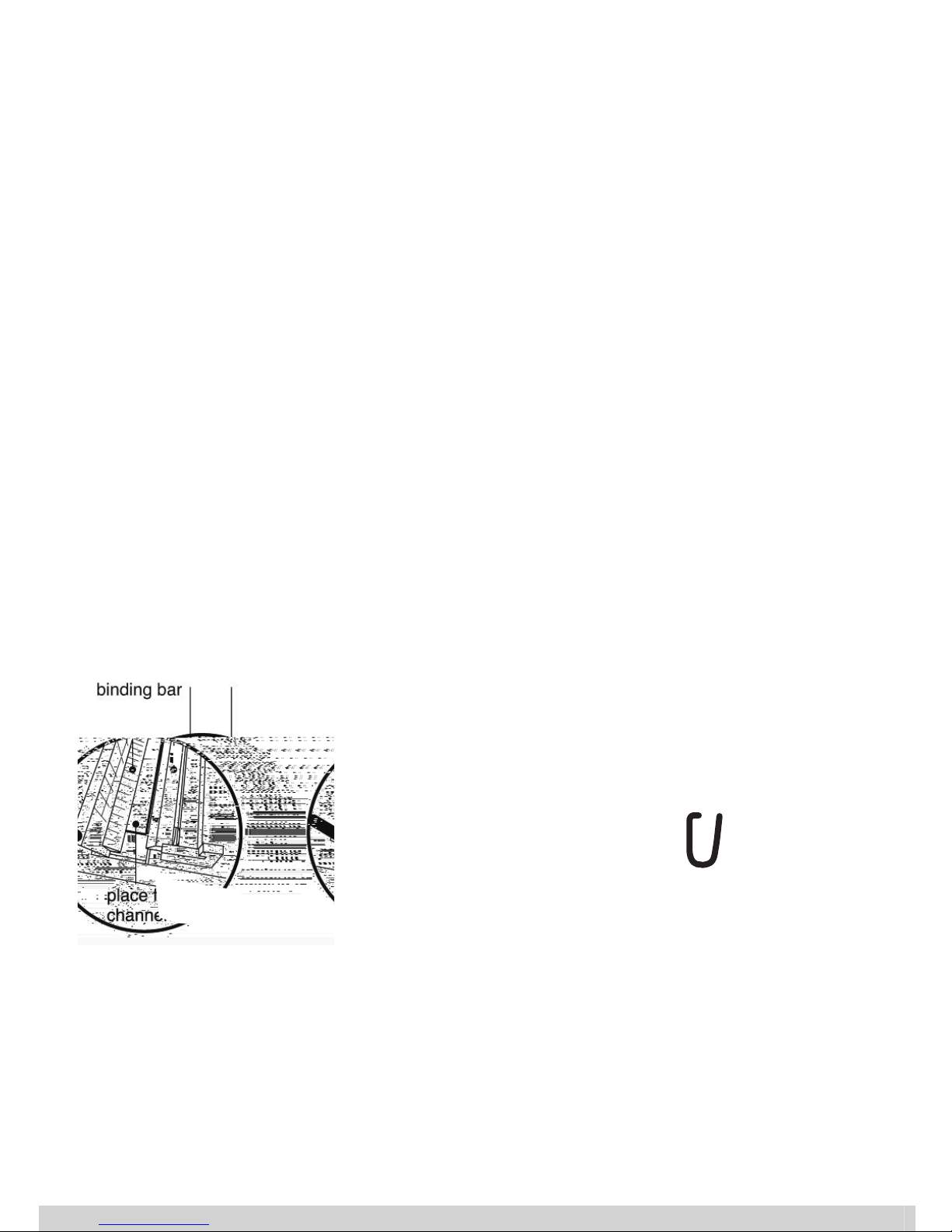
Before starting to use, install a magnetic guide bar and binding bar supplied,
magnetic guide bar on the binding jaw (for channel 5-32 mm) or in front of the
binding jaw (for channel 1,5mm; 3mm) and binding bar at the back. Now insert
the channel into the binding slot in the correct way, all as shown in the diagrams
below. These bars are specially designed to make inserting the documents and
covers into the channel easily.
In the box, there is a de-binding wedge (Metalbind), which is stored in a slot on
the bottom of housing. In addition, these slots on both sides are used for lifting
and moving around the equipment for safety.
INSTALLATION
4
PDJQHWLF
JXLGHEDU
PDJQHWLF
JXLGHEDU
ELQGLQJVORW
ZLWKFKDQQHO
PDJQHWLF
JXLGHEDU
ELQGLQJVORW
ZLWKFKDQQHO
Page 5
MBE 300 • User guide
GB
MBE-300 is based on a popular binding systems. It has an electrically driven
binding mechanism, which assures parallel movement of the jaw guaranteeing an
even closing of the channel. The motor and the options are controlled by
a microprocessor with a LCD display making the control of the MBE-300 easy to
operate and giving you many options. The left hook measures the thickness of the
document and tells you which channel to use.
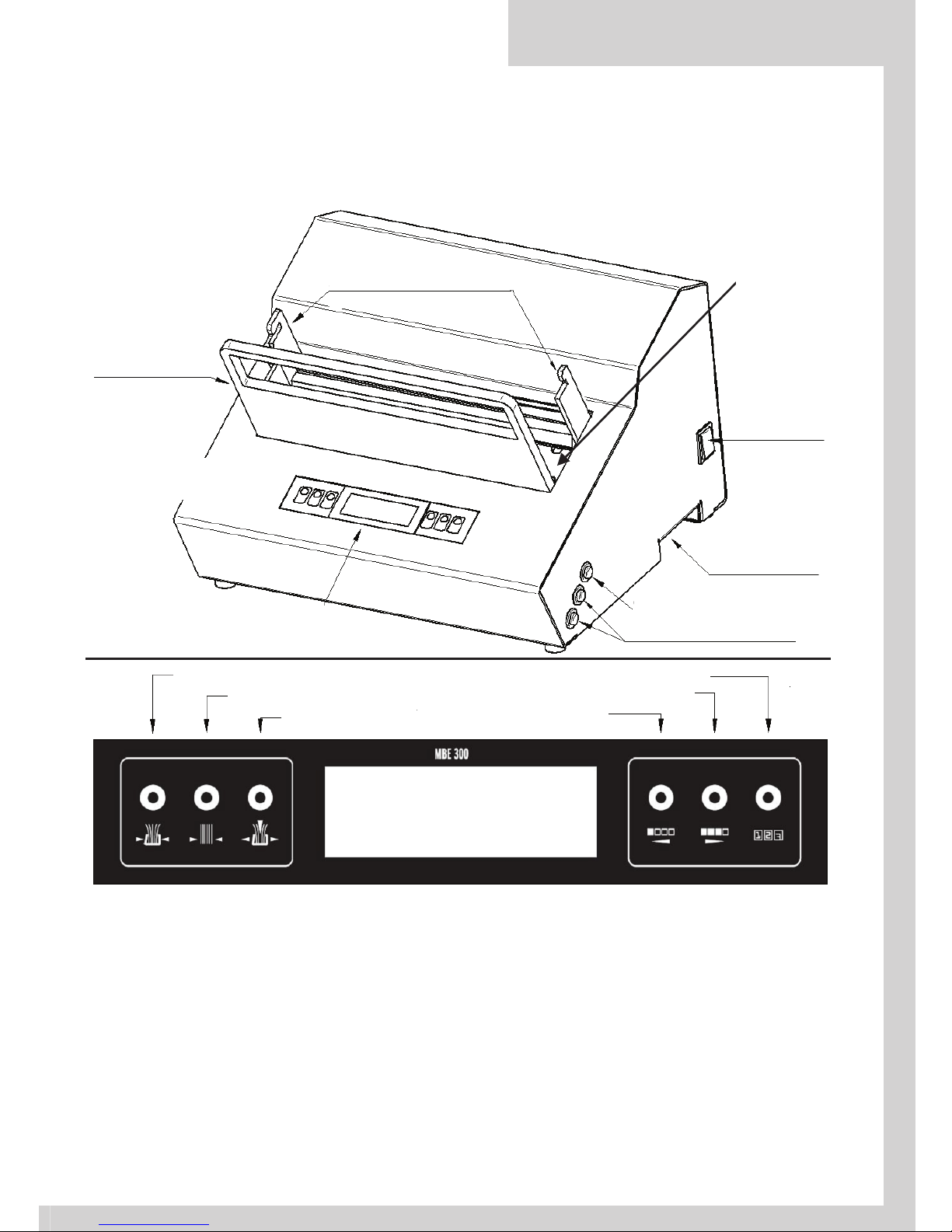
EQUIPMENT LAYOUT
5
'(%,1',1*+22.6
'2&80(17
7+,&.1(66
0($685(,1*6/27
'2&80(17
%,1',1*
6/27
'2&80(177+,&.1(660($685(0(17
32:(5
6:, 7&+
6725$*()25
'(%,1',1*:('*(
/,)7,1*+$1'/(6
23(1%87721
67$57$1'%,1',1*%877216
&21752/3$1(/:,7+/&'',63/$<
DE - BINDING HOOKS
DOCUMENT
BINDING
SLOT
POWER SWITCH
DOCUMENT
THICKNESS
MEASUREING SLOT
OPEN BUTTON
START AND BINDING BUTTONS
CONTROL PANEL WITH LCD DISPLAY
STORAGE FOR
DE-BINDING WEDGE
LIFTING HANDLES
BINDING
DEBINDING
DOCUMENT THICKNESS MEASUREMENT
BINDING PRESSURE
BINDING PRESSURE+
COUNTER
Page 6

PREPARATION TO WORK
CHOOSING YOUR BINDING SYSTEM (METALBIND OR C-BIND)
1. Plug the power cable into the back and then into the electric socket.
2. Turn the equipment on by the switch on the right side. The display shows infor-
mation about the equipment version and the total number of documents bound
to date.
3. The equipment defaults to the binding mode.
4. To change the modes, press the button on the panel.
Note!
When powering up the machine it is possible to change the binding system to
Metalbind or C-BIND. To change the system, when device is switched o ,
press and hold BINDING button and then turn on the power. The LCD display
will show:
• MBE-300 for Metalbind system or
• CBE-300 for C-BIND system.
BINDING WITH THE METALBIND SYSTEM
1. On the display are shown daily number of bound documents and the pressure
level. This information can be changed by pressing the counter or pressure
button.
2. In accordance with the information on the display, place the channel into the
binding slot, straight side of the channel must be on the moving side of the jaw,
and the curved side must be on the de-binding plate.
3. Press and hold both START buttons, the jaw will moves to the channel and stop,
now release the buttons.
4. The channel is now locked in place.
5. Now put the documents and covers inside the channel, ensuring they are
square, tight to the bottom of the channel.
6. Press and hold both START buttons again, the equipment will start to bind the
documents and covers together. Hold the START buttons until you hear
a bleep signal for the end of the process and release the button.
There are 4 diff erent binding pressure modes available, the most universal is
level 3, which can be used on a wide range of documents and covers. This mode is
the default mode when switching on the equipment. If it is necessary to change the
binding pressure, you can do this on the control panel. This is because of using
shorter channels, channels with soft coverings or binding together very tough
materials.
7. After the binding process, the jaw automatically moves back leaving just enough
space to remove the bound documents and covers.
8. Take out bound documents.
6
Page 7
MBE 300 • User guide
GB
After the binding process the jaw does not fully open. This is to shorten the
binding process when doing many jobs of the same type. When you want to bind
wider channels, you must move the jaw to the fully open position.
At any time of the binding process, you can stop the process by releasing the
START buttons. By pressing the buttons again, you can continue the process.
DOCUMENT THICKNESS MEASURING METALBIND
1. Press the DOCUMENT THICKNESS MEASUREMENT button.
2. Place the documents with covers into the measurement slot, as it is shown on
the diagram below.
3. At the same time holding the covers and documents, press and hold both START
buttons, they will stop when the measurement is taken then release the start
buttons.
4. The document thickness measurement starts from the fully open position to
guarantee precise results.
5. The jaw closes on to the document and covers, when the left hook touches the
document the channel size is shown on the LED display panel.
If you see, two sizes on the LCD display i.e. 13 (16) this means that the
document and covers have reached the borderline thickness. Preferred channel is
13 mm but if you have a problem with fi tting the documents inside the channel, use
a 16 mm channel.
6. The jaw moves back.
At any time, you can stop the process by releasing the START buttons.
7
PLACE THE DOCUMENT INTO
MEASUREMENT SLOT
Page 8
8
DEBINDING METALBIND
1. Press DE-BINDING button on the LED panel.
De-binding process starts from the fully open position.
2. Hold the document by the channel with the straight side of the channel upward.
3. Place the de-binding wedge (see picture) sharp edge towards the channel and
with the angled side upwards with the blade about 8 pages in from the top,
place the whole document with the wedge on to the hooks.
4. For de-binding channels 1,5 mm and 3 mm, use the de-binding adapter. Place
the de-binding adapter on the channels, small slot is for 1,5 mm, bigger for 3mm.
5. Holding the book, then press and hold the START buttons.
6. The wedge is pushed into the document and expands the channel, after the
debinding process the jaw will move back to the fully open position.
7. Remove the wedge, document and channel together carefully from the
equipment, then remove the wedge from the document, then the channel.
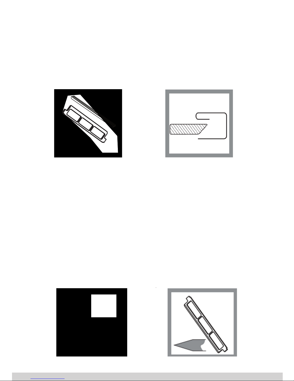
CBIND SYSTEM
OPUS MBE-300 equipment allow to bind in Metalbind and in C-BIND systems. To
bind in C-BIND system you need additional accessories:
insert O.CB Insert for MBE 300 (diag 1); debinding wedge O.CB Debinding
Tool for Atlas 300 / MB 300 / MBE 300 (diag 2)
'(
5
J
n
o
Page 9

MBE 300 • User guide
GB
9
BINDING WITH THE C-BIND SYSTEM
1. On the display are shown daily number of bound documents and the pressure
level. This information can be changed by pressing the counter or pressure
button.
2. In accordance with the information on the display, place the cover with documents into the binding slot.
3. Press and hold both START buttons, the equipment will start to bind the documents and covers together. Hold the START buttons until you hear a bleep signal
for the end of the process and release the button.
There are 4 diff erent binding pressure modes available, the most universal is level
3, which can be used on a wide range of documents and covers. This mode is the
default mode when switching on the equipment. If it is necessary to change the
binding pressure, you can do this on the control panel. This is because of using
shorter covers, covers with soft coverings or binding together very tough materials.
4. After the binding process, the jaw automatically moves back leaving just enough
space to remove the bound documents and covers.
5. Take out bound documents.
After the binding process the jaw does not fully open. This is to shorten the
binding process when doing many jobs of the same type. When you want to bind
wider channels, you must move the jaw to the fully open position.
At any time of the binding process, you can stop the process by releasing the
START buttons. By pressing the buttons again, you can continue the process.
DOCUMENT THICKNESS MEASURING (C-BIND)
1. Press the DOCUMENT THICKNESS MEASUREMENT button.
2. Place the documents without covers into the measurement slot, as it is shown
on the diagram below.
3. At the same time holding the documents, press and hold both START buttons,
they will stop when the measurement is taken then release the start buttons.
4. The document thickness measurement starts from the fully open position to
guarantee precise results.
5. The jaw closes on to the document and covers, when the left hook touches the
document the channel size is shown on the LED display panel. If you see, two
sizes on the LCD display i.e. A (B) this means that the document has reached the
borderline thickness. Preferred cover size is A but if you have a problem with
fi tting the documents inside the channel, use a size B cover.
6. The jaw moves back.
At any time, you can stop the process by releasing the START buttons.
Page 10

10
DEBINDING (C-BIND)
1. Press DE-BINDING button on the LED panel. De-binding process starts from the
fully open position.
2. Place the de-binding wedge O.CB Debinding Tool for Atlas 300 / MB 300 / MBE
300 (see picture) sharp edge towards the spine and in a center of documents,
place the whole document with the wedge on to the hooks.
3. Holding the book, then press and hold the START buttons.
4. The wedge is pushed into the document and expands the channel, after the de
-binding process the jaw will move back to the fully open position.
5. Remove the wedge, document and channel together carefully from the equipment, then remove the wedge from the document, then the channel.
PLACE THE DOCUMENT INTO
MEASUREMENT SLOT
Page 11

MBE 300 • User guide
GB
11
COUNTER
The equipment has two counters:
• daily
• total to date
Daily counter is cleared when you switch off the equipment. If the counter is not
visible on the display, it can be turned on by pressing the COUNTER button, which
will display both Daily and Total. Daily counter, can also be cleared at any time if
necessary by pressing the counter button for two seconds. To see the total number
of bound documents it is necessary to press the COUNTER button. If the button is
Page 12

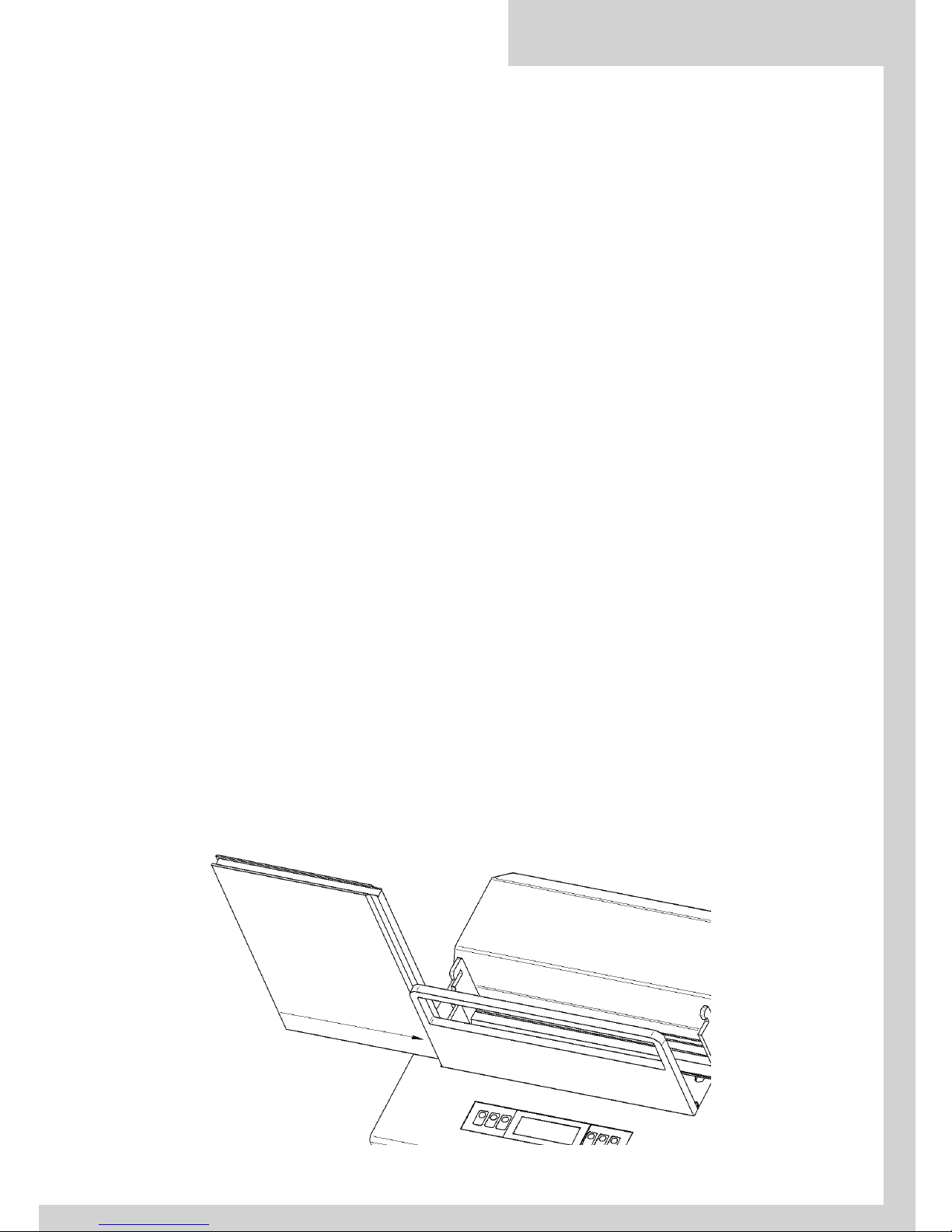
SOFTWARE UPGRADE
You are able to upgrade the MBE-300 with new versions of software when
availed, ask your supplier about the interface to link up a computer.
You must put the equipment into the service position as shown on a diagram
below.
Interface must be connected to the USB port and in accordance with the software
guide to transfer the new version to the equipment.
The equipment must be placed into the service position to remove the bottom
cover. To open the cover it is necessary to remove 6 screws on the top and bottom
edges of the bottom cover.
RECOMMENDED MATERIALS
The equipment is designed to bind sheets of paper of diff erent thicknesses
and many types of covers made from covered card or plastic. Before binding other
materials, we suggest that you check the binding eff ectiveness of the product.
It is recommended that you use all binding products from the OPUS range of
materials such as the Metalbind system, covers and channels of OPUS.
You can use other products, without damaging the equipment, however the
eff ectiveness and quality, we cannot guarantee or the outcome.
86%3257
6&5(:6
72%(
5(029('
12
SCREW
TO BE
REMOVED
USB PORT
Page 13

MBE 300 • User guide
GB
POSSIBLE PROBLEMS
CALIBRATION PROCESS
Press and hold COUNTER button for 15 seconds until, Calibration is shown
on LCD screen. Next press and hold both START buttons and do not take your
fi ngers of the buttons until it stops.
MAINTENANCE
The equipment does not require any lubrication or periodic checks. Places
that need to be oiled are oiled and sealed during the manufacturing process at the
production stage. The cover of the equipment is powder coated and baked hard.
To clean the equipment you can use general household cleaning products.
Do not use solvents or petroleum-based products.
PROBLEM CAUSE SOLUTION
Display does not work.
The plug is not connected to the socket.
Lack of power in the socke.
Equipment damage.
Connect the plug to the socket
correctly.
Check main fuse or connect to diff erent socket.
contact the supplier.
The motor moving the
jaw does not work.
The motor has overheated.
(see the LED display for information)
Equipment damage.
Wait for the motor to cool down (5 to
15 minutes) (see the LED display for
information).
Contact the supplier.
The equipment works
but does not bind
properly.
The pressure setting is too low.
Equipment damage.
Set a higher binding pressure.
Contact the supplier.
The equipment works
but the jaw stops
intermittently while
moving without any
reason.
Higher resistance values.
Re-calibrate, follow the instructions
in the user’s guide. If the problem
remains, contact the supplier.
13
Page 14

TECHNICAL DATA
• Voltage supply: AC 230 V 50/60 Hz 1 A
• Power consumption: 200 W
• Equipment dimensions (H x W x D): 270 x 410 x 362 mm
• Net weight: 45 kg
• Gross weight: 52 kg
• Max jaws pressure: 2.3 t
• Working temperature: 0 - 30°C
•
Binds and de-binds: up to 300 sheets*
* Tested on: 80 g/m
2
paper
Equipment and products marked with this symbol cannot be deposed together with normal
or municipal waste. The user is required to take their used product to a collection point for
recycling of waste electrical and electronic equipment. Proper segregation of used equipment reduces the negative impact of hazardous substances that may be in there, in to the
environment which could impact, human and wild life health. For more detailed information concerning the disposal of used equipment, please contact your local authority, waste
disposal service or the point of sale where you purchased the product. By ensuring proper
disposal of equipment we are helping to protect the environment, humanity and wild life
health.
07.12.2017 OPUS Sp. z o.o. ● ul. Toruńska 8 ● 44 – 122 Gliwice ● Poland ● www.opus.pl
14
Page 15

MBE 300 • Instrukcja obsługi
PL
Instrukcja obs ugi
PL
MBE 300
15
Page 16

ZASADY BEZPIECZEŃSTWA
• Przed rozpoczęciem pracy z urządzeniem należy zapoznać się z zasadami bezpieczeństwa, zaleceniami producenta i instrukcją obsługi.
• Instrukcję należy zachować i korzystać z niej w przypadku jakichkolwiek wątpliwości
dotyczących obsługi urządzenia.
• Z uwagi na niebezpieczeństwo przygniecenia poruszającą się szczęką bindującą, zaczepami klina debindującego lub klinem debindującym w czasie, gdy jest on założony na
zaczepy, urządzenie może być obsługiwane tylko przez osoby przeszkolone w zakresie
bezpiecznej obsługi w oparciu o obowiązujące przepisy BHP.
• Urządzenie należy ustawić na stabilnym i odpowiednio wytrzymałym podłożu.
• Urządzenie należy chronić przed wilgocią i kurzem.
• Nie wolno ustawiać urządzenia w pobliżu urządzeń grzejnych.
• Nie wolno używać urządzenia w pobliżu łatwopalnych gazów i cieczy.
• Urządzenie można zasilać wyłącznie oryginalnym przewodem sieciowym.
• Gniazdo sieciowe powinno posiadać sprawne uziemienie.
• Napięcie zasilające musi być zgodne z parametrami podanymi na tabliczce znamionowej
znajdującej się na obudowie maszyny.
• Nieprzestrzeganie powyższej zasady może grozić porażeniem prądem i pożarem.
• Należy chronić przewód zasilający urządzenie przed uszkodzeniem, nie należy używać
przewodu sieciowego do przenoszenia urządzenia i wyciągania wtyczki z gniazdka
• Dokonywanie zmian w instalacji elektrycznej urządzenia lub przewodzie sieciowym grozi
porażeniem prądem.
• Całkowite wyłączenie urządzenia następuje po wyjęciu wtyczki z sieci.
• Przed zdjęciem osłon z maszyny należy wyjąć wtyczkę z gniazdka sieciowego i odczekać
około 5 minut do czasu zaniku napięcia w zasilaczu.
• Układ elektryczny zabezpieczono bezpiecznikiem.
• Bezpiecznik jest umieszczony na płytce zasilacza wewnątrz maszyny.
• Jeżeli konieczna jest wymiana bezpiecznika, należy wymienić go na bezpiecznik o takiej
samej wartości.
• Jeżeli nowy bezpiecznik także uległ przepaleniu należy zwrócić się o pomoc do serwisu.
• Ze względów bezpieczeństwa maszynę może obsługiwać w danym momencie tylko jedna
osoba.
• Należy zwrócić uwagę, aby podczas pracy maszyny osoby postronne nie znajdowały się w
pobliżu stanowiska pracy urządzenia.
• W celu zabezpieczenia przed przypadkowym uruchomieniem napędu maszyny, zastoso-
Page 17

MBE 300 • Instrukcja obsługi
PL
• Należy kontrolować sprawność urządzenia i w przypadku zauważenia jakichkolwiek nie-
prawidłowości w pracy należy skontaktować się z serwisem.
• Urządzenie jest przeznaczone do pracy ciągłej w pomieszczeniach zamkniętych w tempe-
raturze do +30°C.
• Podczas intensywnej pracy w wyższych temperaturach może wystąpić konieczność przerwania pracy w celu wychłodzenia silnika – pojawi się komunikat o przegrzaniu.
• Wszelkich napraw urządzenia może dokonywać jedynie osoba uprawniona.
• Nie stosować rozpuszczalników do czyszczenia maszyny.
INFORMACJE OGÓLNE
Urządzenie MBE-300 służy do bindowania i debindowania dokumentacji w systemie Metalbind. Po zakupieniu dodatkowych akcesoriów możliwe jest przystosowanie maszyny do pracy w systemie C-BIND. Pracę urządzenia nadzoruje mi-
kroprocesorowy sterownik z panelem sterującym z tekstowym wyświetlaczem LCD.
Możliwe są trzy tryby pracy:
• bindowanie (cztery poziomy siły)
• debindowanie
• tryb doboru rozmiaru kanału (okładki)
Zmiany trybu pracy dokonuje się przez naciśnięcie przycisku oznaczonego odpowiednią ikoną na panelu sterującym.
Urządzenie wyposażono w dwa liczniki ilości bindowań:
• licznik dzienny (z możliwością zerowania)
• licznik całkowitej ilości bindowań (TOTAL)
Obsługa urządzenia nie wymaga specjalnych kwalifi kacji, jednakże przed rozpoczęciem pracy należy zapoznać się z treścią niniejszej instrukcji.
TRANSPORT I PRZECHOWYWANIE
• MBE-300 jest urządzeniem zasilanym elektrycznie przystosowanym do pracy w warunkach biurowych. Zarówno maszyna jak i opakowanie nie powinny być narażane
na wilgoć (np. deszcz).
• W przypadku zawilgocenia lub zalania maszyny konieczne jest przekazanie urzą-
dzenia do serwisu w celu dokonania przeglądu, aby uniknąć ryzyka porażenia
prądem!
• Maszyna może być transportowana i przechowywana zarówno w wysokich dodatnich
jak i w ujemnych temperaturach.
• Opakowanie zabezpiecza maszynę podczas upadku z niewielkiej wysokości, jednak
zaleca się ostrożne obchodzenie się z urządzeniem.
• Do transportu maszyna została przymocowana do drewnianej palety.
• z uwagi na masę urządzenia zaleca się transportowanie maszyny przy użyciu wózka
paletowego.
17
Page 18

• Zaleca się przechowywanie opakowania przez okres gwarancji .
• MBE-300 jest urządzeniem przystosowanym do pracy w warunkach biurowych.
• Maszynę należy ustawić na odpowiednio wytrzymałej, płaskiej i stabilnej powierzchni.
• Jeżeli maszyna była narażona na ujemne temperatury, to przed pierwszym włączeniem do sieci należy odczekać kilkadziesiąt minut – może wystąpić skroplenie się pary wodnej na zimnych metalowych elementach.
• Dla bezpieczeństwa operatora urządzenie można zasilać wyłącznie oryginal-
nym przewodem zasilającym.
• Gniazdo sieciowe powinno posiadać sprawne uziemienie.
• Napięcie zasilające musi być zgodne z parametrami podanymi na tabliczce
znamionowej znajdującej się na obudowie maszyny.
• Nieprzestrzeganie powyższych zasad może grozić porażeniem prądem i pożarem.
• Przed uruchomieniem maszyny zamontuj wkładkę magnetyczną oraz wkładkę
bindującą (dołączone w pudełku z akcesoriami).
• Wkładkę magnetyczną zamontuj na szczęce bindującej (dla kanałów 5-32mm)
lub przed szczęką bindującą dla kanałów 1,5, 3mm, a wkładkę bindującą przy
płycie debindującej.
• Wkładki ułatwiają wkładanie dokumentacji do kanału, ścięte boki obu wkładek
powinny być skierowane do wnętrza szczeliny (jak pokazano na rysunku).
W pudełku z akcesoriami znajduje się klin służący do debindowania w systemie
Metalbind. Miejsce do przechowywania klina znajduje się w dolnej osłonie maszyny między wnękami ułatwiającymi przenoszenie urządzenia.
INSTALACJA
ǁŬųĂĚŬĂďŝŶĚƵũČĐĂ
ŵĂŐŶĞƚLJĐnjŶĂ
ǁŬųĂĚŬĂ
ƉƌŽǁĂĚnjČĐĂ
ŵŝĞũƐĐĞ
ŶĂŬĂŶĂų
ǁŬųĂĚŬĂďŝŶĚƵũČĐĂ
ŵĂŐŶĞƚLJĐnjŶĂ
ǁŬųĂĚŬĂ
ƉƌŽǁĂĚnjČĐĂ
ŵŝĞũƐĐĞ
ŶĂŬĂŶĂų
ZNáDGND
ELQGXMąFD
kanał
1.5;3 mm
V]F]ĊND
ELQGXMąFD
PDJQHWLF
JXLGHEDU
PDJQW\F]QD
ZNáDGND
SURZDG]ąFD
kanał
5-32 mm
ZNáDGND
ELQGXMąFD
PDJQHW\F]QD
ZNáDGND
SURZDG]ąFD
V]F]ĊND
ELQGXMąFD
18
WKŁADKA BINDUJĄCA
MIEJSCE
NA KANAŁ
WKŁADKA
BINDUJĄCA
SZCZĘKA
BINDUJĄCA
SZCZĘKA
BINDUJĄCA
MAGNETYCZNA
WKŁADKA
PROWADZĄCA
WKŁADKA
BINDUJĄCA
MAGNETYCZNA
WKŁADKA
PROWADZĄCA
MAGNETYCZNA
WKŁADKA
PROWADZĄCA
KANAŁ
5-32 mm
KANAŁ
1.5-3 mm
Page 19

MBE 300 • Instrukcja obsługi
PL
MBE-300 jest maszyną zbudowaną na bazie konwencjonalnej bindownicy
kanałowej. Posiada jedną ruchomą szczękę napędzaną równolegle przez dwie
śruby, połączone pasem zębatym z silnikiem. Mechanizm zapewnia równoległość
prowadzenia szczęki, co gwarantuje równomierne zaciśnięcie kanału. Pracę silnika
nadzoruje mikroprocesorowy sterownik z wyświetlaczem LCD. Podczas bindowania
szczęka zaciska kanał oparty poprzez wkładkę na stałej płycie debindującej. Na tej
samej płycie opiera się też debindowana oprawa oraz mierzona dokumentacja.
Zaczepy służą do mocowania klina debindujacego, lewy zaczep pełni także funkcję
elementu pomiarowego.
BUDOWA URZĄDZENIA
19
WNĘKA DO DOBORU
ROZMIARU KANAŁU
WYŁĄCZNIK
SIECIOWY
PRZYCISK COFANIA SZCZĘKI
PRZYCISK START ZACISK SZCZĘKI
WNĘKA DO
PRZECHOWYWANIA
KLINA DEBINDUJĄCEGO
/ UCHWYTY
DO PRZENOSZENIA
PANEL STERUJĄCY Z WYŚWIETLACZEM
ZACZEPY KLINA DEBINDUJĄCEGO
BINDOWANIE
DEBINDOWANIE
LICZNIK
SIŁA BINDOWANIA
SIŁA BINDOWANIA
DOBÓR ROZMIARU KANAŁU (OKŁADKI)
Page 20

PRZYGOTOWANIE DO PRACY
WYBÓR SYSTEMU (METALBIND LUB C-BIND)
1. Włącz wtyczkę do źródła zasilania.
2. Włącz zasilanie przełącznikiem umiejscowionym po prawej stronie obudowy
urządzenia (wyświetlacz zaświeci się i pojawi się informacja o wersji maszyny
oraz ilości wykonanych bindowań).
3. Maszyna rozpoczyna pracę zawsze w trybie BINDOWANIE.
4. Jeżeli chcesz wybrać inny tryb pracy naciśnij odpowiedni przycisk.
Uwaga!
Przy włączaniu urządzenia możliwa jest zmiana trybu bindowania Metalbind
lub C-BIND. Aby zmienić tryb należy przy wyłączonym urządzeniu nacisnąć
i przytrzymać przycisk BINDOWANIE i następnie włączyć zasilanie. Na
wyświetlaczu pojawi się wtedy odpowiedni napis:
• MBE-300 w przypadku trybu Metalbind,
• CBE-300 w przypadku trybu C-BIND.
BINDOWANIE W SYSTEMIE METALBIND
1. Na wyświetlaczu pokazana jest informacja o stanie licznika dziennego lub poziomu siły bindowania. Wskazanie można zmienić naciskając przycisk siły lub
przycisk licznika.
2. Zgodnie z informacją na wyświetlaczu włóż kanał do szczeliny (prosta krawędź
kanału powinna być po stronie ruchomej szczęki, zagięta zaś po stronie płyty
debindującej).
3. Naciśnij i przytrzymaj obydwa przyciski START (zwróć uwagę, że czas pomiędzy
naciśnięciem jednego i drugiego przycisku nie może być większy niż 0,2 sekundy).
4. Szczęka dojedzie do kanału i zatrzyma się – kanał został przytrzymany, aby ułatwić wprowadzenie dokumentacji. Włóż dokument do kanału.
5. Ponownie naciśnij i przytrzymaj jednocześnie dwa przyciski START. Maszyna wykona bindowanie.
Dostępne są cztery poziomy siły bindowania. Najbardziej uniwersalnym jest poziom siły 3, który jest odpowiedni do większości zastosowań. Ten poziom jest ustawiony po każdym załączeniu maszyny. Jeżeli wystąpi konieczność zmniejszenia lub
zwiększenia siły bindowania (np. używasz kanałów krótszych niż 300 mm, kanałów
z delikatną okleiną, albo bindujesz bardzo twarde materiały) naciśnij odpowiedni
przycisk na panelu sterującym.
6. Po zbindowaniu szczęka automatycznie cofnie się pozostawiając wystarczającą
ilość miejsca na swobodne wyjęcie oprawy (przytrzymaj przyciski START, do momentu pojawienia się sygnału dźwiękowego, który oznacza koniec procesu).
7. Wyjmij zbindowaną dokumentację.
20
Page 21

MBE 300 • Instrukcja obsługi
PL
Szczęka po bindowaniu nie powraca do pozycji spoczynkowej. Pozwala to na
skrócenie czasu dojazdu do kanału. Jeżeli chcesz bindować większy kanał to
wycofaj szczękę do właściwej pozycji.
W każdej chwili możesz przerwać proces bindowania puszczając przyciski
START. Po ponownym naciśnięciu przycisków proces będzie kontynuowany. Jeżeli
podczas bindowania cofniesz szczękę – proces rozpocznie się od początku (od
przytrzymania kanału).
POMIAR GRUBOŚCI DOKUMENTACJI W SYSTEMIE METALBIND
1. Naciśnij przycisk DOBÓR ROZMIARU KANAŁU.
2. Przyłóż dokument wraz z okładkami do płyty debindującej jak na rysunku.
3. Naciśnij jednocześnie i przytrzymaj przyciski START.
4. Pomiar zawsze rozpoczyna się od pozycji spoczynkowej, aby zagwarantować
najdokładniejszy wynik – jeśli szczęka nie znajdowała się na niej najpierw zostanie wycofana.
5. Szczęka dojedzie do dokumentu, a gdy lewy zaczep klina oprze się o dokument
na wyświetlaczu pojawi się informacja jakiego kanału należy użyć.
Jeśli na wyświetlaczu pojawią się dwie wielkości (w tym jedna w nawiasie) np.:
13 (16) – oznacza to, że została wykryta graniczna grubość dokumentacji. Prefero-
wany rozmiar kanału to 13 mm; jednak w przypadku problemów z umieszczeniem dokumentu w okładce należy użyć kanału w rozmiarze 16 mm.
6. Szczęka wycofa się, informacja o rozmiarze kanału będzie wyświetlana tylko do
momentu osiągnięcia pozycji spoczynkowej szczęki.
W dowolnej chwili możesz przerwać proces puszczając przyciski START.
21
WSUŃ DOKUMENT DO
SZCZELINY POMIAROWEJ
Page 22

DEBINDOWANIE W SYSTEMIE METALBIND
1. Naciśnij przycisk DEBINDOWANIE. Proces debindowania musi się rozpocząć z pozycji spoczynkowej szczęki.
2. Chwyć dokument za kanał w taki sposób, aby zagięty bok kanału był na górze,
a prosty na dole.
3. Wsuń klin debindujący (patrz rysunek poniżej) do dokumentu ostrzem w stronę
kanału i całość załóż na zaczepy.
4. Dla kanałów 1,5mm; 3mm użyj dodatkowej wkładki debindującej. Wkładkę debindującą nałóż na kanał (węższą szczeliną na kanał 1,5mm; szerszą na kanał
5mm).
5. Naciśnij i przytrzymaj jednocześnie przyciski START.
6. Klin zostanie wciśnięty między kartki dokumentacji rozginając kanał, następnie
szczęka wycofa się do pozycji spoczynkowej.
7. Wyjmij ostrożnie dokument wraz z klinem – dokumentacja została zdebindowana.
PRACA W SYSTEMIE CBIND
Po zakupieniu dodatkowych akcesoriów, maszyna może pracować w systemie
C-BIND. Dostępne akcesoria:
wkładka bindująca O.CB Insert for MBE 300 (rysunek 1)
klin debindujący O.CB Debinding Tool for Atlas 300 / MB 300 / MBE 300 (rysunek 2)
'(
5
J
n
o
22
Page 23

MBE 300 • Instrukcja obsługi
PL
BINDOWANIE W SYSTEMIE C-BIND
1. Na wyświetlaczu pokazana jest informacja o stanie licznika dziennego lub poziomu siły bindowania. Wskazanie można zmienić naciskając przycisk siły lub
przycisk licznika.
2. Zgodnie z informacją na wyświetlaczu włóż oprawę do szczeliny bindującej.
3. Naciśnij i przytrzymaj obydwa przyciski START (zwróć uwagę że, czas pomiędzy
naciśnięciem jednego i drugiego przycisku nie może być większy niż 0,2 sekundy).
4. Szczęka dojedzie do kanału i wykona bindowanie.
Dostępne są cztery poziomy siły bindowania. Najbardziej uniwersalnym jest
poziom siły 3, który jest odpowiedni do większości zastosowań. Ten poziom jest
ustawiony po każdym załączeniu maszyny. Jeżeli wystąpi konieczność zmniejszenia lub zwiększenia siły bindowania (np. używasz opraw krótszych niż 300 mm,
z delikatną okleiną, albo bindujesz bardzo twarde materiały) naciśnij odpowiedni
przycisk na panelu sterującym.
5. Po zbindowaniu szczęka automatycznie cofnie się pozostawiając wystarczającą
ilość miejsca na swobodne wyjęcie oprawy (trzymaj przyciski START, do momentu pojawienia się sygnału dźwiękowego, który oznacza koniec procesu).
6. Wyjmij zbindowaną dokumentację.
Szczęka po bindowaniu nie powraca do pozycji spoczynkowej. Pozwala to na
skrócenie czasu dojazdu do kanału. Jeżeli chcesz bindować większy kanał to
wycofaj szczękę do właściwej pozycji.
W każdej chwili możesz przerwać proces bindowania puszczając przyciski
START. Po ponownym naciśnięciu przycisków proces będzie kontynuowany. Jeżeli
podczas bindowania cofniesz szczękę – proces rozpocznie się od początku (od
przytrzymania kanału).
POMIAR GRUBOŚCI DOKUMENTACJI W SYSTEMIE C-BIND
1. Naciśnij przycisk DOBÓR ROZMIARU KANAŁU.
2. Przyłóż samą dokumentację (bez okładki) do płyty debindującej jak na rysunku.
3. Naciśnij jednocześnie i przytrzymaj przyciski START.
4. Pomiar zawsze rozpoczyna się od pozycji spoczynkowej, aby zagwarantować
najdokładniejszy wynik – jeśli szczęka nie znajdowała się na niej najpierw zostanie wycofana.
23
Page 24

5. Szczęka dojedzie do dokumentacji, a gdy lewy zaczep klina oprze się o doku-
ment na wyświetlaczu pojawi się informacja jakiego rozmiaru okładki należy
użyć. Jesli na wyswietlaczu pojawią się dwie litery (w tym jedna w nawiasie) np.:
A (B) – oznacza to, że została wykryta graniczna grubość dokumentacji. Preferowany rozmiar okładki to A; jednak w przypadku problemów z umieszczeniem
dokumentacji w okładce należy użyć okładki w rozmiarze B.
6. Szczęka wycofa się, informacja o rozmiarze kanału będzie wyświetlana tylko do
momentu osiagnięcia pozycji spoczynkowej szczęki.
W dowolnej chwili możesz przerwać proces puszczając przyciski START. Oprawiana
dokumentacja musi mieć grubość co najmniej 1,8 mm. Jesli dokumentacja jest
cieńsza, koniecznie użyj pasków wypełniających (np. O•Filling Sticky dostępnych w
ofercie OPUS) tak, aby zwiększyć grubość oprawianych dokumentów.
24
WSUŃ DOKUMENT DO
SZCZELINY POMIAROWEJ
Page 25

MBE 300 • Instrukcja obsługi
PL
DEBINDOWANIE W SYSTEMIE C-BIND
1. Naciśnij przycisk DEBINDOWANIE. Proces debindowania musi się rozpocząć z pozycji spoczynkowej szczęki.
2. Wsuń klin debindujący (rysunek poniżej) O.CB Debinding Tool for Atlas 300 / MB
300 / MBE 300 do dokumentu ostrzem w stronę kanału i całość załóż na zaczepy.
3. Naciśnij i przytrzymaj jednocześnie przyciski START.
4. Klin zostanie wciśnięty między kartki dokumentacji rozginając kanał, następnie
szczęka wycofa się do pozycji spoczynkowej.
5. Wyjmij ostrożnie dokument wraz z klinem – dokumentacja została zdebindowana.
LICZNIK
Maszyna wyposażona jest w dwa liczniki:
• dzienny,
• całkowity.
Licznik dzienny kasowany jest każdorazowo po wyłączeniu zasilania. Jeżeli
licznik nie jest wyświetlany na wyświetlaczu można go wywołać naciskając przycisk
LICZNIK. Licznik dzienny można w dowolnej chwili skasować. Naciśnięcie przycisku
LICZNIK powoduje pokazanie na wyświetlaczu stanu licznika całkowitego. Jeżeli
przytrzymamy przycisk przez 2 sekundy licznik dzienny zostanie wyzerowany.
Licznik całkowitej ilości bindowań jest pokazywany podczas startu maszyny.
25
Page 26

AKTUALIZACJA OPROGRAMOWANIA
Istnieje możliwość zapisania do pamięci sterownika nowej wersji
oprogramowania. W tym celu należy ustawić maszynę w pozycji serwisowej (jak na
rysunku poniżej). Do złącza USB podłącz przewód i zgodnie z opisem programu do
transferu danych załaduj nową wersję oprogramowania do maszyny MBE-300.
Ustawienie maszyny w pozycji serwisowej jest również sugerowane, gdy
konieczne jest otwarcie pokrywy dolnej. Aby otworzyć pokrywę trzeba odkręcić
6 śrub umieszczonych na dolnej i górnej krawędzi pokrywy.
ZALECANE MATERIAŁY
Maszyna przeznaczona jest do bindowania dokumentacji złożonej z pliku
kartek oraz okładek kartonowych lub foliowych. Przed zastosowaniem innych
materiałów zaleca się sprawdzić skuteczność bindowania.
Do bindowania zaleca się stosowanie kanałów metalowych Metalbind (lub
okładek C-BIND) produkcji OPUS. Przy stosowaniu kanałów (okładek) innych
producentów nie ma niebezpieczeństwa uszkodzenia maszyny, jednakże
skuteczność bindowania nie jest gwarantowana.
=áąF]QH8 6%
$E\]GMąüSRNU\ZĊ
GROQąQDOHĪ\
RGNUĊFLüWHĞUXE\
26
ABY ZDJĄĆ POKRYWĘ
DOLNĄ NALEŻY
ODKRĘCIĆ TE ŚRUBY
ZŁĄCZE USB
Page 27

MBE 300 • Instrukcja obsługi
PL
MOŻLIWE NIEPRAWIDŁOWOŚCI
KALIBRACJA NAPĘDÓW (WYKONYWAĆ W OSTATECZNOŚCI)
Wcisnąć przycisk Licznik i trzymać około 15 sekund do momentu pojawienia
się informacji Calibration na wyświetlaczu, następnie wcisnąć przyciski START i
trzymać je do zakończenia procesu kalibracji - maszyna przejdzie do trybu
bindowania.
KONSERWACJA
Maszyna nie wymaga smarowania, ani okresowych przeglądów. Punkty
wymagające smarowania zostały zakonserwowane fabrycznie.
Obudowa maszyny pokryta jest lakierem proszkowym. Do czyszczenia
można używać ogólnie dostępnych środków. Nie stosować rozpuszczalników!
NIEPRAWIDŁOWOŚĆ MOŻLIWA PRZYCZYNA DZIAŁANIA
Wyświetlacz nie świeci
się.
Wtyczka nie jest włączona do sieci.
Brak napięcia w gniazdku.
Uszkodzenie urządzenia.
Włącz wtyczkę do sieci.
Włącz maszynę do innego gniazda.
Skontaktuj się z dostawcą.
Silnik napędzający
szczękę nie daje się
uruchomić.
Silnik został przegrzany (na wyświetlaczu
jest wyświetlony komunikat).
Uszkodzenie urządzenia.
Zaczekaj aż silnik wystudzi się (około
5 - 15 minut), aż komunikat zniknie.
Skontaktuj się z dostawcą.
Urządzenie pracuje, ale
siła bindowania jest
zbyt mała.
Ustawiona zbyt mała siła bindowania.
Uszkodzenie urządzenia.
Ustaw większą siłę bindowania.
Skontaktuj się z serwisem.
Urządzenie pracuje, ale
często bez powodu
szczęka zatrzymuje się
w trakcie ruchu.
Zwiększyły się opory pracy urządzenia.
Wykonaj kalibrację napędu zgodnie
z instrukcją kalibracji, jeżeli to nie
wyeliminuje problemu, skontaktuj się
z dostawcą.
27
Page 28

DANE TECHNICZNE
• Napięcie znamionowe: AC 230 V 50/60 Hz 1 A
• Maksymalny pobór mocy: 200 W
• Wymiary maszyny (W x S x G): 270 x 410 x 362 mm
• Waga urządzenia netto: 45 kg
• Waga urządzenia brutto: 52 kg
• Maksymalny nacisk szczęki: 2,3 t
• Temperatura pracy: 0 - 30°C
• Binduje oraz debinduje: do 300 kartek*
* testy wykonano na papierze 80 g/m
2
Zużyty sprzęt oznakowany niniejszym symbolem nie może być umieszczany i usuwany
łącznie z innymi odpadami, w tym odpadami komunalnymi. Obowiązkiem użytkownika jest
przekazanie zużytego produktu do punktu zbiórki w celu recyklingu odpadów powstałych
ze sprzętu elektrycznego i elektronicznego. Właściwa segregacja i selektywna zbiórka
odpadów zużytego sprzętu zmniejsza negatywne oddziaływanie substancji niebezpiecznych, które mogą się w nim znajdować, na środowisko naturalne i zdrowie człowieka.
W celu uzyskania bardziej szczegółowych informacji dotyczących utylizacji zużytego sprzętu
prosimy skontaktować się z przedstawicielem władz lokalnych, dostawcą usług utylizacji
odpadów lub punktem sprzedaży, gdzie nabyto produkt. Zapewniając prawidłową utylizację sprzętu pomagamy chronić środowisko naturalne.
07.12.2017 OPUS Sp. z o.o. ● ul. Toruńska 8 ● 44 – 122 Gliwice ● Poland ● www.opus.pl
28
 Loading...