

Page 1

Atlas 190 • User’s guide
GB
Atlas 190
User’s guide
GB
Page 2
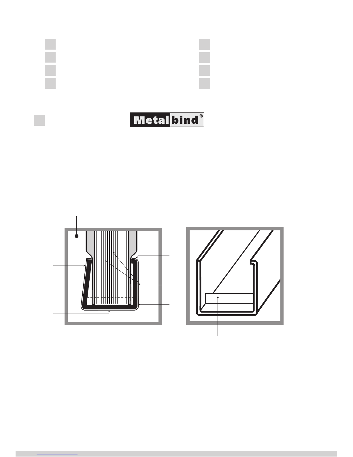
1 - The back wall of the channel is bent in to hold covers and pages.
2 - The channel is powder coated and covered with an embossed material.
3 - The special shaped Metalbind channel gives a perfect front look of your bound document.
4 - Pages are not touched or harmed by the channel they are protected by the covers.
5 - The front view of the cover is never misshaped or deformed.
6 - The special protrusions at each end help to centre the covers and documents
in the channel and stops them moving before binding.
METALBIND SYSTEM
Atlas 190 was designed to use channels and covers from the METALBIND system.
The covers and the documents are clamped together from the outside by a
Metalbind channel. Covers are larger and protect the documents and edges from
damage, channels only touched by the covers plus making them secure and in
their original condition. Metalbind is the strongest binding method.
A special feature o the Atlas 190 is that it can also bind and de-bind covers
from the C-Bind system.
1
Contents:
1 METALBIND SYSTEM
DESCRIPTION
HEALTH & SAFETY
PREPARATION TO WORK
BINDING WITH METALBIND
DEBINDING WITH METALBIND
CBIND SYSTEM
TECHNICAL DATA
1
2
4
3
5
6
Metalbind
Page 3
Atlas 190 • User’s guide
GB
3
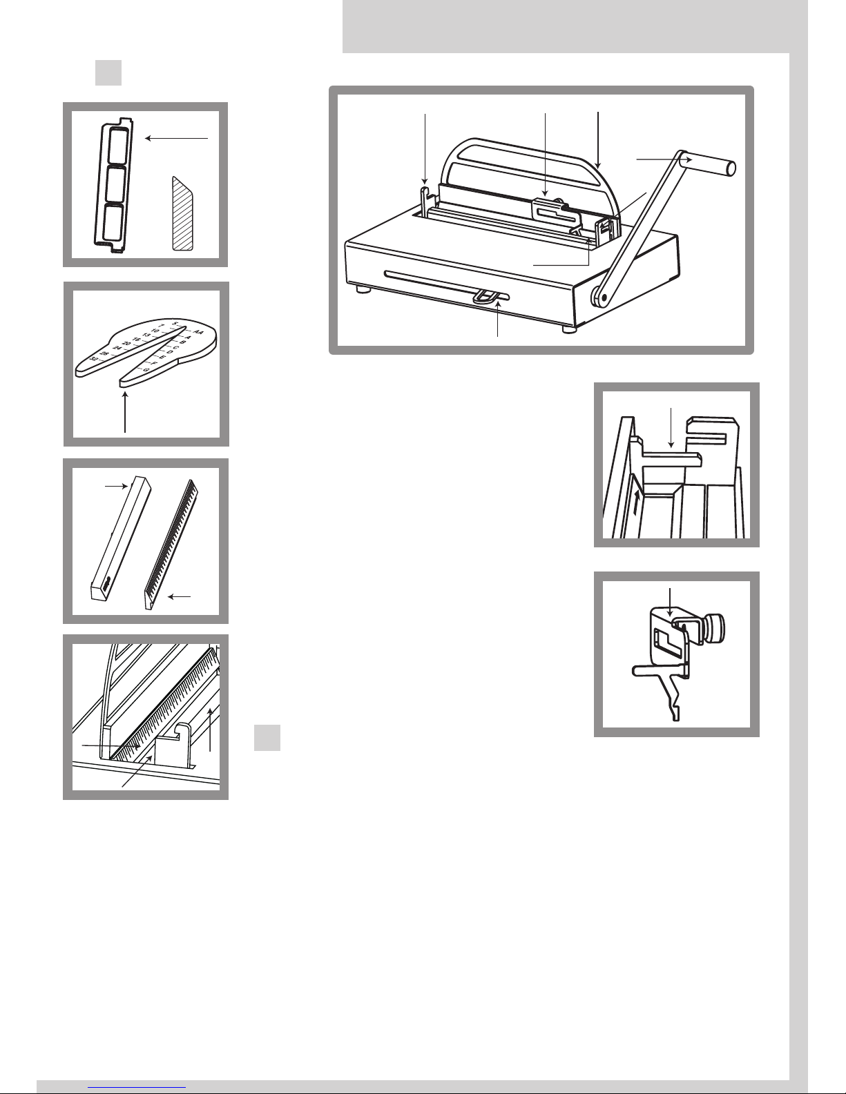
DESCRIPTION2
1 - bind and de-binding handle
2 - clamp lever
3 - binding slot
4 - de-binding hooks
5 - de-binding wedge (Metalbind)
6 - channel width selecting tool
7 - front bar of the COVERguide system
8 - back bar of the COVERguide
system with ruler
9 - fixed side stop
10 - adjustable side stop
11 - extended back support
HEALTH & SAFETY
• Before operating the equipment read the Health & Safety
precautions, manufacturers recommendations and the
operation/user manual
• The operation/user manual should be easily available at any
time for the operator
• The equipment must be kept away and out of reach
of children
• Equipment must be protected against dust and damp
and should be positioned on a strong and sturdy flat surface
• While binding, do not put fingers into the binding slot
• Be careful when moving the equipment it is very heavy
• Pay attention the de-binding wedge has sharp edges
• The machine must not be used for any other purposes
6
5
7
11
10
10
9
4
4
8
3
7
3
2
1
8b
8b
8
7
Page 4
other than those indicated in the operating/user manual
• It is necessary to check and supervise if the equipment is being used and operated
correctly, before reporting any malfunctions or problems to the service department
or dealer
• Equipment must not be located outside or operated in temperatures under 8˚C / 46.4˚F
and must be operated in accordance with the general Health & Safety rules
failure to do so could cancel the guarantee
• Repairs must be carried out by authorized sta, during the guarantee period, failure to
do so could cancel the guarantee
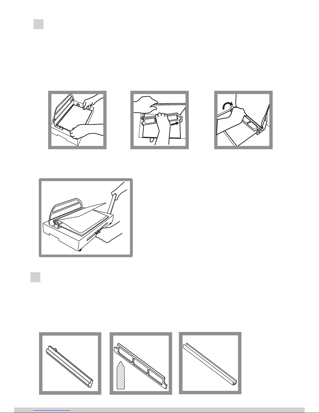
PREPARATION TO WORK
After taking the device out of the packing box, start assembling the equipment, attach the
extended back support (11) on to the lower back support, to the pre drilled holes with the
Allen key and screws supplied, now fit the bind & de-binding handle (1) with the bolt and
Allen key supplied, in the hole in the side and tightened firmly.
Now place the two plastic bars called (COVER GUIDE SYSTEM) (7 & 8) in the binding slot
(8) with the ruler at the back of the slot, and the second bar (7) with magnets at the front
(see diagram on the opposite page)
The cover guide system has been specially designed to help you insert the covers and
documents into the channel easily and centre covers and documents when using smaller
channels.
It is very important that the cover guide system is fitted correctly in the binding slot (3)
the sloped edges of the bars should be facing each other in the binding slot please check by
looking at the diagram. (see diagram on the opposite page).
The equipment is now ready for work.
BINDING WITH METALBIND
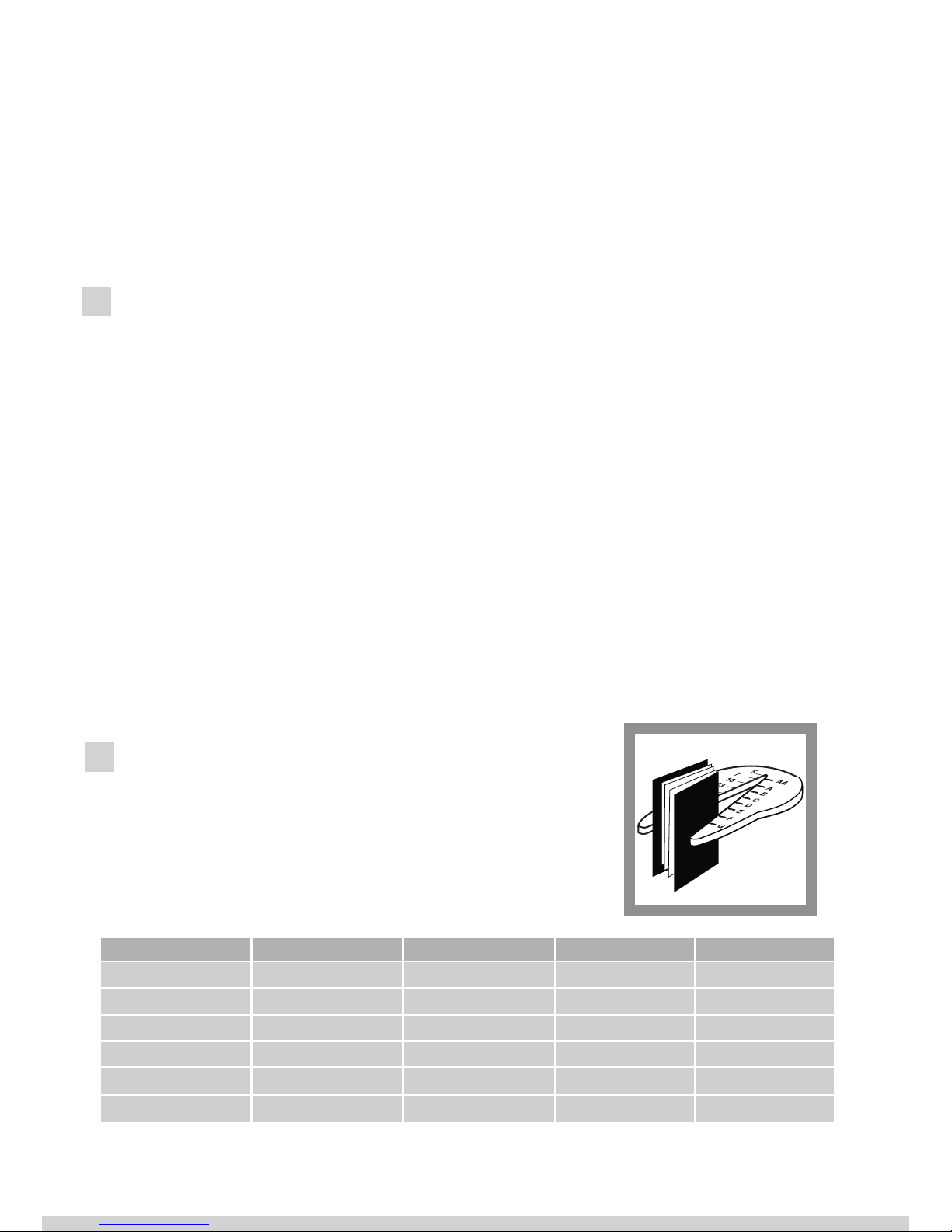
1. Use channel width selecting tool (6) or table below to
choose size of channel.
H = hard cover. p = pages. T = transparent cover. S = soft cover. O = no cover.
Example: H/p/H =(H) hard cover/ (p)pages / (H) hard cover
4
Size of channel H/p/H H/p/T S/p/S O/p/O
5 10 - 31 10 - 33 10 - 34 10 - 38
7 32 - 60 34 - 63 35 - 63 39 - 67
10 61 - 89 64 - 92 64 - 92 68 - 97
13 90 - 118 93 - 121 93 - 121 98 - 126
16 119 - 148 122 - 150 122 -150 127 - 155
20 149-186 151 - 189 151 - 190 156 - 190
5
Page 5
Atlas 190 • User’s guide
GB
Important!
The thickness of the documentation
to be bound must be at least 1,8 mm
(with the cover). If the documentation is
thinner, it is necessary to use the filling strips
called O.filling Sticky, available from OPUS
o make document thick enough to bind.
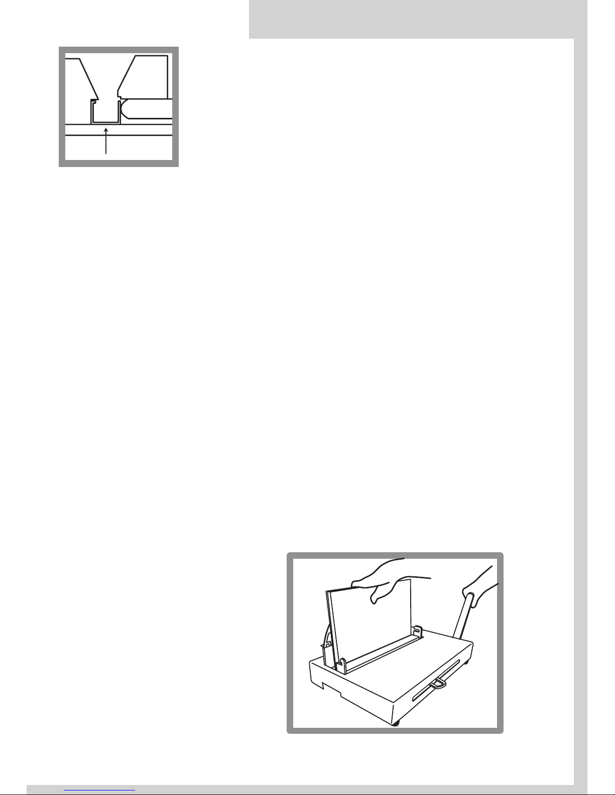
7 - front edge guide for binding jaw
8 - back guide with ruler
A - channel
B - binding jaw
2. Make sure the binding bars also called cover guide system are correctly inserted into the binding slot (3) (see PREPARATION TO WORK and diagram above).
3. Pull up the bind and de-binding handle (1) to the open position, vertical.
4. Move the clamp lever (2) completely to the left.
5. Put the channel into the binding slot (3) between the bars (7 and 8) and insure that the channel is tight against the side stop (9) and the front of the channel is against the binding bar (8)
see diagram above.
When using smaller channels than A4 fit the adjustable side stop (10). Centre the smaller
channel by using the ruler on the back bar in the slot and tighten the side stop (10)and do as
in point 5 above.
6. Close the clamp lever (2) to the right until you can feel resistant’s on the lever.
7. Take the pile of documents insure they are even, put it between the covers, check the pages
are centred in relation to the edges of covers.
8. Take the documents and covers and push carefully into the channel between the protrusions
in the binding slot. NOTE that 5 mm O.CHANNELS and all O.SIMPLE CHANNELS do not have protrusions. Note! Make sure the back cover is facing you.
9. Push down firmly on the bind & de-binding handle (1) holding the covers and documents
vertical till you feel the handle will go no further.
10. Now pull up the bind & de-binding handle (1) to the open position, vertical.
Move the clamp lever (2) to the left completely to take out the bound documents.
11. If the documents are not clamped together firm enough, repeat the process 9 and 10. above
again.
12. You may remove binded documentation.
Important!
Be sure the back cover faces you.
8
7
A
B
back cover
1
2
Page 6
DEBINDING WITH METALBIND
1. Lift the binding handle(1) up to the open position.
2. If fitted remove adjustable stop.
3. Ensure the clamp lever(2) is completely to the left,open.
4. Put the bound document flat on the equipment face down, back cover up.
5. Push the bound document, channel against the back support,firmly.
6. Open the bound document 5 to 6 pages from the back cover.
7. Fit the right end of the wedge (5) blade edge towards
the channel, in the right hook (4) then place the left
end of the wedge into the left hook (4).
8. Move the clamp lever (2) to the right till you feel
some resistance, holding the lever.
9. Push down the binding handle (1) carefully, holding the clamp lever (2) at the same time, move the
handle (1) up and down at the same time move the
clamp lever (2) to the right carefully until the pages
are just loose enough to come out of the channel.
10. Lift the handle (1) up, release clamp lever (2) and remove the document together with the wedge, then
take the wedge out of the document carefully.
11. Make the planned changes to the document and
re-bind. The cover may be re-used (a maximum of
three times).
CBIND SYSTEM
Accessories for binding, measuring, de-binding covers of the C-Bind system.
• Channel width selecting tool (6)
• O.CB Insert for Atlas 190. for binding C-Bind covers, two part kit for all covers (dig.1)
• O.CB Debinding tool for Atlas 190 - de-binding wedge (dig.2) and AA cover de-binding jig tool (dig.3)
6
7
2
1
De-binding
dig. 1 dig. 2
dig. 3
back
cover
Page 7

Atlas 190 • User’s guide
GB
Sheet binding chart for the C-Bind system.
Measure the thickness of the sheets to be bound,
without covers. Select appropriate cover using the
chart above. Then use the same binding procedure
as Metalbind (see chapter 5).
2. Documents to bind must have a minimum thickness of 1.8 mm, thinner must be bound
using a filler strip called O.Filling Sticky from OPUS, these increase the thickness
for binding. Before binding C-BIND covers remove the Metalbind binding bar (8) with
ruler and insert the O.CB Insert for Atlas 190 binding bar, see (dig.1).
3. To de-bind C-BIND cover use O.CB de-binding wedge for Atlas 190 (Dig.2).
Important! The AA cover de-binding jig tool included in the (O.CB Debinding Tool for
Atlas 190) should be fitted on the spine edge of AA cover before debinding.
4. Follow the same binding and de-binding methods as in Metalbind, chapters 5 and 6.
While binding or de-binding with C-Bind System, front or back of cover may face you.
TECHNICAL DATA
• Binds and de-binds up to 190 sheets* = 380 pages **
• Dimensions: H-180 x W-435 x D-320 mm
• Net weight: 16.1 kg
• Gross weight: 18.5 kg
* Tested on 80 g/m2 paper
** Printed each side
8
Channel size Inumber of sheet
AA
soft cover 15-40
hard cover 20-40
A
41-90
B
91-120
C
121-145
D
146-185
1. Using the channel width selecting tool (6), measure the thickness of the documents
without the cover or choose the appropriate cover from the chart below.
Page 8

Page 9

Atlas 190 • Instrukcja obsługi
PL
Atlas 190
Instrukcja obs ugi
PL
Page 10

1 - tylna ściana kanału jest pochylona aby przytrzymywać okładki i kartki dokumentacji
2 - kanał jest wykończony elegancką okleiną
3 - specjalny kształt kanału zapewnia perfekcyjny wygląd dokumentacji
4 - strony nie ulegają uszkodzeniu
5 - przednia ściana nie ulega deformacji
6 - ogranicznik kanału - specjalne ograniczniki ułatwiające dokładne wycentrowanie dokumentów
wraz z okładkami, jak również uniemożliwiające przemieszczanie się stron dokumentacji
wzdłuż kanału
SYSTEM METALBIND
Urządzenie bindujące Atlas 190 jest przeznaczone do oprawiania dokumentacji
(bindowania) przy użyciu okładek i kanałów wykonanych w systemie Metalbind.
Bindowanie polega na zaciskaniu pliku kartek wraz z okładkami od zewnątrz
przez metalowy kanał.
1
SPIS TREŚCI:
1 System METALBIND
2 Opis urządzenia
3 Zasady bezpieczeństwa
4 Przygotowanie
urządzenia do pracy
5 Bindowanie METALBIND
6 Debindowanie METALBIND
7 System C-BIND
8 Dane techniczne
1
2
4
3
5
6
Metalbind
Okładki oraz kartki są przytrzymywane przez kanał, co czyni METALBIND
najtrwalszym systemem bindowania.
Page 11

Atlas 190 • Instrukcja obsługi
PL
3
OPIS URZĄDZENIA
2
1 - ramię urządzenia
2 - uchwyt regulujący rozwarcie szczęk
3 - szczelina bindująca
4 - zaczep
5 - klin debindujący
6 - przyrząd doboru rozmiaru kanału/okładki
7 - magnetyczna wkładka prowadząca
8 - wkładka prowadząco - bindująca
9 - ogranicznik
10 - ruchomy ogranicznik
11 - pałąk
ZASADY BEZPIECZEŃSTWA
• przed rozpoczęciem pracy z urządzeniem należy zapoznać się z zasadami bezpieczeństwa, zaleceniami
producenta i instrukcją obsługi
• instrukcję tę należy zachować i korzystać z niej w przypadku jakichkolwiek wątpliwości dotyczących
obsługi urządzenia
• urządzenie należy chronić przed wilgocią i kurzem
• urządzenie należy trzymać poza zasięgiem dzieci
• urządzenie należy ustawić na stabilnej powierzchni o odpowiedniej wytrzymałości
• w trakcie zaciskania nie wkładać rąk do szczeliny bindującej!
• zachować ostrożność przy przenoszeniu urządzenia.
• możliwość wysunięcia się elementów ze schowka
• należy uważać na ostre krawędzie klina debindującego
• nie wolno używać urządzenia do innych celów niż określone w instrukcji obsługi
6
5
11
10
10
9
4
4
8
3
7
3
2
1
8b
8
7
Page 12

• należy kontrolować sprawność urządzenia.
• w przypadku zauważenia jakichkolwiek nieprawidłowości w pracy, należy skontaktować
się z serwisem
• urządzenie jest przeznaczone wyłącznie do pracy w pomieszczeniach zamkniętych
• urządzenie należy obsługiwać zawsze zgodnie z ogólnymi zasadami BHP
• wszelkich napraw urządzenia może dokonywać jedynie osoba uprawniona.
PRZYGOTOWANIE URZĄDZENIA DO PRACY
Po wyjęciu urządzenia z opakowania, za pomocą załączonych kluczy imbusowych przykręć
śrubami pałąk (11) do podpory debindującej oraz solidnie przykręć ramię urządzenia (1) do
obudowy.
Do urządzenia dołączone są dwie wkładki:
• magnetyczna wkładka prowadząca (7) (znajduje się na szczelinie bindującej (3)
• wkładka prowadząco-bindująca (8) (znajduje się w schowku z boku urządzenia razem
z klinem debindującym)
Połóż odpowiedniąwkładkę prowadząco-bindującą przy tylnej ścianie szczeliny bindującej
(3) wraz zmagnetyczną wkładką prowadzącą (7). Prawidłowe ułożenie wkładek pokazuje
przekrój poprzeczny na rysunku w rozdziale piątym (BINDOWANIE METALBIND).
Urządzenie jest gotowe do pracy.
BINDOWANIE METALBIND
1. Przy pomocy przyrządu lub poniższej tabeli dobierz rozmiar kanału.
T/k/T – okładka twarda/plik kartek/okładka twarda
T/k/P – okładka twarda/plik kartek/okładka przezroczysta
M/k/M – okładka miękka/plik kartek/okładka miękka
B/k/B – plik kartek zbindowany jedynie za pomocą kanału
4
5
Rozmiar kanału T/k/T T/k/P M/k/M B/k/B
5 10 - 31 10 - 33 10 - 34 10 - 38
7 32 - 60 34 - 63 35 - 63 39 - 67
10 61 - 89 64 - 92 64 - 92 68 - 97
13 90 - 118 93 - 121 93 - 121 98 - 126
16 119 - 148 122 - 150 122 -150 127 - 155
20 149-186 151 - 189 151 - 190 156 - 190
Page 13

Atlas 190 • Instrukcja obsługi
PL
Uwaga!
Oprawiana dokumentacja musi mieć
grubość co najmniej 1,8 mm (razem
z okładką). Jeśli dokumentacja jest cieńsza, koniecznie użyj pasków wypełniających (np. O•Filling Sticky dostępnych
w ofercie OPUS) tak, aby zwiększyć grubość
oprawianych dokumentów.
7 - magnetyczna wkładka
prowadząca
8 - wkładka prowadząco–bindująca
12 - szczęka bindująca
(dociska prostą ściankę kanału)
13 - kanał
2. Upewnij się, że w szczelinie bindującej znajdują się odpowiednio ułożone wkładki, patrz
rozdział czwarty (PRZYGOTOWANIE URZĄDZENIA DO PRACY).
3. Podnieś ramię urządzenia (1) maksymalnie do góry.
4. Przesuń uchwyt regulujący rozwarcie szczęk (2) maksymalnie w lewo.
5. Pomiędzy wkładkę (8) i szczękę (12) włóż kanał, a następnie dosuń go maksymalnie w
prawo do ogranicznika (9). W przypadku kanałów mniejszych niż A4 należy zastosować
ogranicznik ruchomy (10). Pozycję ogranicznika ruchomego określamy przy pomocy podziałki na wkładce (8), pozycja = połowie długości kanału.
Uwaga! ograniczniki ruchome stosować tylko w przypadku kanałów mniejszych niż A4.
Przed rozpoczęciem procesu debindowania ograniczniki należy ściągnąć.
6. Uchwyt regulujący rozwarcie szczęk (2) przesuń w prawo aż poczujesz opór.
7. Wyrównany plik kartek włóż między okładki i zwróć uwagę, aby kartki były wycentrowane względem brzegów okładek. W niektórych kanałach znajdują się ograniczniki, które
uniemożliwiają przemieszczanie się papieru wzdłuż kanału. W tym wypadku należy włóżyć plik kartek pomiędzy tymi ogranicznikami.
8. Tak przygotowane pliki kartek wraz z okładkami włóż do kanału (13) znajdującego się
w szczelinie bindującej (3), a następnie przesuń w prawo uchwyt regulujący rozwarcie
szczęk (2), aż poczujesz opór.
Uwaga! Upewnij się, że tylna okładka znajduje się przodem do ciebie.
8
7
13
12
9. Opuść ramię (1) w dół.
10. Podnieś ramię (1), a uchwyt regulujący rozwarcie szczęk (2) przesuń w lewo.
Uwaga! W niektórych przypadkach (np. zbyt duży rozmiar kanału w stosunku do ilości
oprawianych kartek) może się okazać, że kanał nie został prawidłowo zaciśnięty ( jest zbyt
luźny). W takiej sytuacji przesuń uchwyt regulujący rozwarcie szczęk (2) w prawo, aż poczujesz
opór i powtórz punkty 9 i 10.
11. Wyciągnij zbindowany dokument.
2
1
tylna
okładka
Page 14

2
1
DEBINDOWANIE METALBIND
1. Połóż dokument na maszynie tak, aby tylna okładka znajdowała się na górze.
2. Pałąk (11) odsuń maksymalnie do tyłu i zdemontuj ogranicznik ruchomy (10) (jeśli
nie został już wcześniej usunięty).
3. Podnieś ramię urządzenia (1).
4. Otwórz dokument kilka milimetrów od tylnej okładki.
5. Wsuń prawy koniec klina debindującego (5) w prawy zaczep debindujący (4).
Ścięta krawędź klina (5) musi być skierowana w stronę grzbietu dokumentu.
6. Przenieś lewy koniec klina debindującego (5) ponad lewymzaczepem (4), a następnie zamocuj gowzaczepie.
7. Przesuń uchwyt (2) maksymalnie w prawo, aż
napotka na opór.
8. Pchnij ramię bindownicy (1) w dół jednocześnie
drugą ręką przytrzymując uchwyt
regulujący rozwarcie szczęk (2). Po podniesieniu
ramienia (1) za pomocą uchwytu (2) zredukuj
powstały luz, a następnie kilkakrotnie
powtórz czynność.
9. Ramię urządzenia (1) podnieś do góry.
10. Zdejmij klin z zaczepów debindujących (4)
i delikatnie wyciągnij kanał z okładki.
11. Dokonaj zaplanowanych zmian w dokumentacji.
Do ponownej oprawy możesz użyć tych
samych okładek i kanału (maksymalnie trzy razy).
SYSTEM C-BIND
Urządzenie bindujące Atlas 190 może również oprawiać dokumentacje w systemie C-BIND.
Akcesoria umożliwiające bindowanie i debindowanie okładek systemu C-BIND:
• przyrząd doboru rozmiaru okładki/kanału (6)
• wkładka bindująca - rys.1 (do nabycia osobno jako O.CB Insert for Atlas 190)
• klin debindujący do okładek C-BIND - rys.2 (do nabycia osobno wraz z nakładką
dla okładek AA - rys. 3 w zestawie O.CB Debinding Tool for Atlas 190)
6
7
DEBINDOWANIE
Przed rozpoczęciem bindowania C-Bind wyciągnij wkładki (7) i (8). Na kołki znajdujące się
na tylnej ściance nałóż wkładkę bindującą O.CB INSERT for Atlas 190 (rys.1)
rys. 1 rys. 2
rys. 3
5
tylna
okładka
4
4
Page 15

Atlas 190 • Instrukcja obsługi
PL
2. Oprawiana dokumentacja musi mieć grubość co najmniej 1,8 mm. Jeśli dokumen tacja jest cieńsza, koniecznie użyj pasków wypełniających (np. O•Filling Sticky
dostępnych w ofercie OPUS), tak aby zwiększyć grubość oprawianych dokumentów.
3. Do debindowania należy użyć klinu debindującego do okładek C-BIND (rys.2).
Uwaga! W przypadku debindowania okładek w rozmiarze AA zastosuj specjalną nakładkę
(znajdującą się w zestawie O.CB Debinding Tool for Atlas 190), którą należy włożyć na
grzbiet oprawionej dokumentacji (rys.3).
4. Bindowanie i debindowanie okładek systemu C-BIND odbywa się analogicznie do systemu Metalbind. Podczas bindowania i debindowania okładka może znajdować się przodem lub tyłem do Ciebie, ułożenie klina nie ma znaczenia (jest symetryczny).
DANETECHNICZNE
• maks ilość oprawianych kartek .................................................................................190*
• waga netto (z wkładką, ogranicznikami formatu, klinem deb., przymiarem, wkładkami coverguide) .................16,1 kg
• waga brutto ..................................................................................................... 18,5 kg
• wymiary (W x S x G) ........................................................................... 180 x 435 x 320 mm
*próby wykonano na papierze o gramaturze 80 g/m²
8
Rozmiar okładki Ilość oprawianych kartek
AA
okładka miękka 15-40
okładka twarda 20-40
A
41-90
B
91-120
C
121-145
D
146-185
1. Przy pomocy przyrządu lub poniższej tabeli dobierz rozmiar okładki.
Page 16

KARTA GWARANCYJNA
na sprzedaną
w dniu: ...............................................
maszynę: ...............................................
nr fabryczny: ...............................................
podpis sprzedawcy
pieczątka firmowa
program
OPUS wykona naprawę serwisową Twojego urządzenia w rekordowym czasie 72
godzin! Czas liczymy od momentu dostarczenia do serwisu maszyny przez firmę
kurierską DHL, do momentu zwrócenia naprawionej maszyny kurierowi.
Koszt transportu urządzenia w obie strony ponosi OPUS.*
* Aby skorzystać ze specjalnej oferty SERVICE 72 konieczne jest wysłanie przez klienta urządzenia w oryginalnym
opa
kowaniu. Karta gwarancyjna powinna być kompletna i prawidłowo wypełniona z czytelną datą, pieczątką, podpisem
sprzedawcy oraz kopią dokumentu sprzedaży. Oferta dotyczy maszyn w cenie zakupu do 1900 PLN netto.
Firma OPUS ma przyjemność udzielić:
2 - letniej gwarancji na wszystkie urządzenia OPUS i niszczarki EBA
5 –letniej gwarancji na niszczarki IDEAL (do modelu 2503cc)
Dożywotniej gwarancji na noże tnące w niszczarkach IDEAL i EBA
(za wyjątkiem niszczarek: shredcat, micro-cut, super micro-cut, wysokowydajnych oraz
OMD i HDP
W przypadku jakichkolwiek skreśleń lub poprawek
karta gwarancyjna traci ważność.
Page 17

Atlas 190 • User’s guide
GB
Atlas 190
WARUNKI GWARANCJI
1.
Punktem serwisowym dla produktów i towarów OPUS objętych niniejszą gwarancją jest serwis
firmy OPUS Sp. z o.o. w Gliwicach , ul. Toruńska 8.
2
.
Gwarancja dotyczy towarów zakupionych w Polsce i jest ważna wyłącznie na terytorium
Rzeczpospolitej Polskiej.
3
.
Przez naprawę gwarancyjną rozumie się wykonanie przez punkt serwisowy czynności specja-
listycznych, właściwych dla usunięcia wady objętej gwarancją. Naprawa gwarancyjna nie obejmuje czynności przewidzianych do wykonania przez użytkownika we własnym zakresie i na
własny koszt, które opisane są w instrukcji obsługi urządzenia.
4
.
Gwarancja uznawana jest tylko w przypadku, gdy karta gwarancyjna będzie kompletnie
i prawidłowo wypełniona z czytelną datą, pieczątką, podpisem sprzedawcy oraz kopią
dokumentu sprzedaży. Zalecane jest oryginalne opakowanie. W przypadku jego braku OPUS nie
ponosi odpowiedzialności za ewentualne uszkodzenia urządzenia podczas transportu.
Niespełnienie któregokolwiek z warunków daje prawo do odmowy wyk
onania naprawy
gwarancyjnej. W razie utraty karty gwarancyjnej duplikaty nie będą wydawane.
5
.
Firma OPUS zobowiązuje się usunąć ewentualne uszkodzenia w terminie 14 dni roboczych od
daty dostarczenia urządzenia do serwisu. Deklarujemy wykonanie naprawy urządzeń w cenie
zakupu poniżej 1900 PLN netto w ciągu 72 godzin –program „Serwis 72 h” – warunki
programu na pierwszej stronie.
6
.
W przypadkach szczególnych i uzasadnionych termin naprawy może ulec wydłużeniu.
7
.
W okresie gwarancyjnym zapewnia się użytkownikowi bezpłatne usuwanie uszkodzeń wynikają-
cych z wad fabrycznych (wady materiałowe, błędy montażowe) wraz z wymianą części.
8
.
Na wszystkie nowe części i podzespoły, wymienione w trakcie naprawy przysługuje gwarancja,
której okres wynosi 12 miesięcy od dnia ich montażu.
9
.
Gwarancja nie obejmuje czynności konserwacyjnych (np. czyszczenia noży w niszczarkach,
wałków w laminatorach) oraz uszkodzeń powstałych w wyniku:
a) nieprzestrzegania instrukcji obsługi (w przypadku braku instrukcji obsługi w opakowaniu
urządzenia klient dokona pisemnego zgłoszenia tego faktu gwarantowi do 7 dni od daty zakupu
w celu niezwłocznego uzupełnienia tego braku przez OPUS),
b) niewłaściwej kon
serwacji i przechowywania urządzenia,
c) użytkowania urządzenia niezgodnie z przeznaczeniem,
d) naturalnego zużycia: wałków i rolek prowadzących w laminatorach, niszczarkach i falcerkach;
sprężyn w bindownicach oraz stępienia noży tnących w bindownicach, niszczarkach,
obcinarkach i gilotynach,
e) działania sił zewnętrznych (przepięcia w sieci, wyładowania atmosferyczne, itp.),
f) dostania się przedmiotów o
bcych do wnętrza urządzenia oraz działania korozji, wilgoci, pyłów,
g) celowego uszkodzenia sprzętu.
10.
Użytkownik traci uprawnienia z tytułu gwarancji w przypadku:
a) zatarcia lub zniszczenia oznaczeń typu i numeru fabrycznego,
b) zerwania plomb i zabezpieczeń fabrycznych oraz oznaczeń gwaranta,
c) uszkodzeń powstałych z winy użytkownika, powodujących trwałe pogorszenie jakości urządzenia
(m. in. przekraczania dopuszczalnego czasu pracy urządzeń, przekraczania parametrów
stosowanych materiałów, pracy ur
opisanych w instrukcji obsługi),
d) ingerencji serwisowej osób nieupoważnionych,
e) korzystania z niewłaściwych materiałów eksploatacyjnych (m. in. przycinanej folii laminacyjnej),
f) niewłaściwych parametrów zasilania,
g) samowolnego dokonywania zmian wpisów w karcie gwarancyjnej.
1
1.
Okres gwarancji ulega przedłużeniu o czas trwania naprawy w serwisie OPUS (transport
do i z serwisu nie jest wliczany w czas, o który przedłuża się obowiązywanie gwarancji).
1
2.
Wszelkie koszty związane z nieuzasadnionym dostarczeniem urządzenia do naprawy
lub wezwaniem serwisu ponosi Kupujący.
1
3.
Gwarancja na sprzedany towar konsumpcyjny nie wyłącza, nie ogranicza, ani nie zawiesza
uprawnień Kupującego, wynikających z niezgodności towaru z umową.
SERWIS:
OPUS Sp. z o.o.
44-122 Gliwice, Toruńska 8
tel. +32/ 420 12 55
fax. +32/ 231 12 29
UWAGI**:...............................................................................................................................
............................................................................................................................................
............................................................................................................................................
..........................................................................................................................
............................................................................................................................................
............................................................................................................................................
......................................................................................................
** wypełnia sprzedawca w przypadku innych uzgodnień
Page 18

Atlas 190
10.
Użytkownik traci uprawnienia z tytułu gwarancji w przypadku:
a) zatarcia lub zniszczenia oznaczeń typu i numeru fabrycznego,
b) zerwania plomb i zabezpieczeń fabrycznych oraz oznaczeń gwaranta,
c) uszkodzeń powstałych z winy użytkownika, powodujących trwałe pogorszenie jakości urządzenia
(m. in. przekraczania dopuszczalnego czasu pracy urządzeń, przekraczania parametrów
stosowanych materiałów, pracy urz
ądzeń w warunkach niedostosowanych do wymagań
opisanych w instrukcji obsługi),
d) ingerencji serwisowej osób nieupoważnionych,
e) korzystania z niewłaściwych materiałów eksploatacyjnych (m. in. przycinanej folii laminacyjnej),
f) niewłaściwych parametrów zasilania,
g) samowolnego dokonywania zmian wpisów w karcie gwarancyjnej.
1
1.
Okres gwarancji ulega przedłużeniu o czas trwania naprawy w serwisie OPUS (transport
do i z serwisu nie jest wliczany w czas, o który przedłuża się obowiązywanie gwarancji).
1
2.
Wszelkie koszty związane z nieuzasadnionym dostarczeniem urządzenia do naprawy
lub wezwaniem serwisu ponosi Kupujący.
1
3.
Gwarancja na sprzedany towar konsumpcyjny nie wyłącza, nie ogranicza, ani nie zawiesza
uprawnień Kupującego, wynikających z niezgodności towaru z umową.
Pieczęć punktu sprzedaży
SERWIS:
OPUS Sp. z o.o.
44-122 Gliwice, Toruńska 8
tel. +32/ 420 12 55
fax. +32/ 231 12 29
UWAGI**:...............................................................................................................................
...
.........................................................................................................................................
............................................................................................................................................
...........................................................................................................................
.................
............................................................................................................................................
............................................................................................................................................
.......................................................................................................
.....................................
** wypełnia sprzedawca w przypadku innych uzgodnień
18/11/2014
Page 19

Atlas 190 • User’s guide
GB
KARTA GWARANCYJNA
REJESTRACJA NAPRAW
Data Data Opis Pieczęć
L.p.
przyjęcia wykonania naprawy i podpis serwisu
Urządzenia prosimy dostarczać:
do punktów sprzedaży, w których zakupiono maszynę lub bezpośrednio do serwisu:
OPUS Sp. z o.o., 44 - 122 Gliwice, ul. Toruńska 8
na sprzedaną
w dniu: ...............................................
maszynę: ...............................................
nr fabryczny: ...............................................
OPUS wykona naprawę serwisową Twojego urządzenia w rekordowym czasie 72
* Aby skorzystać ze specjalnej oferty SERVICE 72 konieczne jest wysłanie przez klienta urządzenia w oryginalnym
opa
sprzedawcy oraz kopią dokumentu sprzedaży. Oferta dotyczy maszyn w cenie zakupu do 1900 PLN netto.
W przypadku jakichkolwiek skreśleń lub poprawek
karta gwarancyjna traci ważność.
Page 20

 Loading...