

Optronis CamPerform CP80-25-M, CamPerform C-72, CamPerform CP80-25-M-72, CamPerform CP80-25-C-72 User Manual
CamPerform
CP80-25-M/C-72
CoaxPress Camera
User Manual
Ref. 1889-SU-01-D


CP80-25-M/C-72 Ref. 1889-SU-01-D Page 1
Contents
Revision 3
General 4
Declaration of conformity 4
RoHS compliance 4
Scope of delivery 5
Optronis customer service 5
Remark, Attention 6
Precautions 6
Camera Power 6
Environmental Conditions 6
General Precautions 7
Camera 8
Electrical Interface 9
Auxiliary (Aux.) connector pinout 9
Camera Power 11
Indicator Lamp (LED) 12
CoaxPress Data Channels 12
Lens mount and handling 13
Nikon F-Mount adapter 13
C-Mount adapter 15
Important features 15
Frame format 15
Minimum Frame rate (@ internal synchronisation) 15
Maximum Frame rate (@ internal synchronisation) 15
Max. Frame Rate Examples: 17
Calculation of Exposure Time 17
Frame Rate (@ external synchronisation) 18
Technical Data 19
General 19
Spectral Response / Transmittance 20
Mechanical Dimensions 21
F-Mount Lens (/CM) 21
Synchronisation Input schematics 23
Synchronisation Output schematics 23
Internal Synchronisation Timing 24
Synchronisation Output 24
External Synchronisation Timing 25
Synchronisation Input “level detection” 25
Synchronisation Output “level detection” 25
Focal Length Calculation 26
Full Sensor Resolution 26
Reduced Sensor Resolution 26
Distance Washer 27
Camera firmware update 29
Camera mapping 31

CP80-25-M/C-72 Ref. 1889-SU-01-D Page 2
Gen<i>Cam 36

CP80-25-M/C-72 Ref. 1889-SU-01-D Page 3
Revision
Cameramodel Date Description
CP80-25-M/C-72
SNr. 1889-ST-xxx
30.04.2013 Firmware 6.01
CP80-25-M/C-72
SNr. 1889-ST-xxx
23.05.2013 Firmware 6.02
Gain = 1,39; Offset < 10
CP80-25-M/C-72
SNr. 1889-ST-xxx
11.11.2013 Firmware 8.0
- Add offset and gain calibration menu in xml file
- Add 'Rolling shutter' mode in the xml file
-Add of 'Granularity' mode which allows to set
exposure time through register when using external
synchronisation of trigger over CoaxPress
CP80-25-M/C-72
SNr. 1889-ST-xxx
28.11.2013 Firmware 8.1
- Add flash configuration in xml file (see
FlashSaveWithAutoStart,
FlashSaveWithoutAutoStart, DisableFlashLoad)
- Add Pixel Format saving in the flash configuration

CP80-25-M/C-72 Ref. 1889-SU-01-D Page 4
General
Declaration of conformity
Manufacturer: Optronis GmbH
Address: Ludwigstr. 2, 77694 Kehl, Germany
We certify and declare under our sole responsibility that the
following apparatus
Product: CP80-25-M-72
CP80-25-C-72
conform with the essential requirements of the EMC Directive
2004/108/EC, based on the following specifications applied:
Specifications: EN 61000-6-3 Emission
EN 61000-6-1 Immunity
Kehl, 23.05.2013
Optronis GmbH
Dr. Patrick Summ
Managing Director
RoHS compliance
CamPerform CP80-25-M/C-72 cameras are Pb free manufactured.

CP80-25-M/C-72 Ref. 1889-SU-01-D Page 5
Scope of delivery
CP80-25-M/C-72 CoaxPress camera
Options: /C: Color sensor (Bayer Pattern)
(IR Cutoff Filter, Specification: 1830-SS-10)
/M: Monochrome sensor
Lens mount: /CM: CMount
/FM: FMount
/FMG: FMount for Nikon G-Lens series
CoaxPress: up to 6,25GBit/channel, 4 channels
Synchronisation Adapter cable
Programming cable (USB2) for firmware update
User Manual (CD-ROM)
Optronis customer service
Optronis GmbH
Ludwigstr 2
77694 Kehl
Germany
Tel: +49 (0) 7851 9126 0
Fax: +49 (0) 7851 9126 10
E-mail: info@optronis.com
For any questions or problems, please do not hesitate to ask our customer
service. Please prepare the following information:
• Camera type: CP80-25-M-72 or CP80-25-C-72
• Serial-Number: see label at the bottom side of the camera
• Frame Grabber
• Operating System (Windows XP/Vista/32bit/64bit …)
• Short description of the problem
CP80-25-M/C-72 Ref. 1889-SU-01-D Page 6
Remark, Attention
This user manual is compliant with the firmware version v.6.02 of the camera.
The following signs are used in the user manual
Remarks and additional information
Attention
Precautions
Camera Power
Please use Power over CoaxPress or as an option the CP80-25-M/C-72
camera power supply (not included in shipment).
Environmental Conditions
Temperature range during operation: < + 45°C (housing temperature)
> 0°C (ambient temperature)
Humidity during operation < 80% non-condensed
At high ambient or housing temperatures the camera lifetime will
be reduced. Avoid camera operation beyond temperature limits.
Please ensure, that the housing temperature will be kept as low as
possible by additional heatsinks.
CP80-25-M/C-72 Ref. 1889-SU-01-D Page 7
General Precautions
Read the user manual carefully before using the camera.
Do not orientate the optical input of the camera to direct sunlight.
Keep the camera free protected from dirt, dust, grease and water.
Make sure that all the connecting cables are in good condition. Defective
cables have to be replaced.
Always unplug the camera before cleaning it. Do not use cleaning liquids or
sprays. Instead, use a dry and soft duster.
There are no serviceable parts inside the camera. Do not open the
housing of the camera.
Warranty becomes void if the camera housing is opened.
CP80-25-M/C-72 Ref. 1889-SU-01-D Page 8
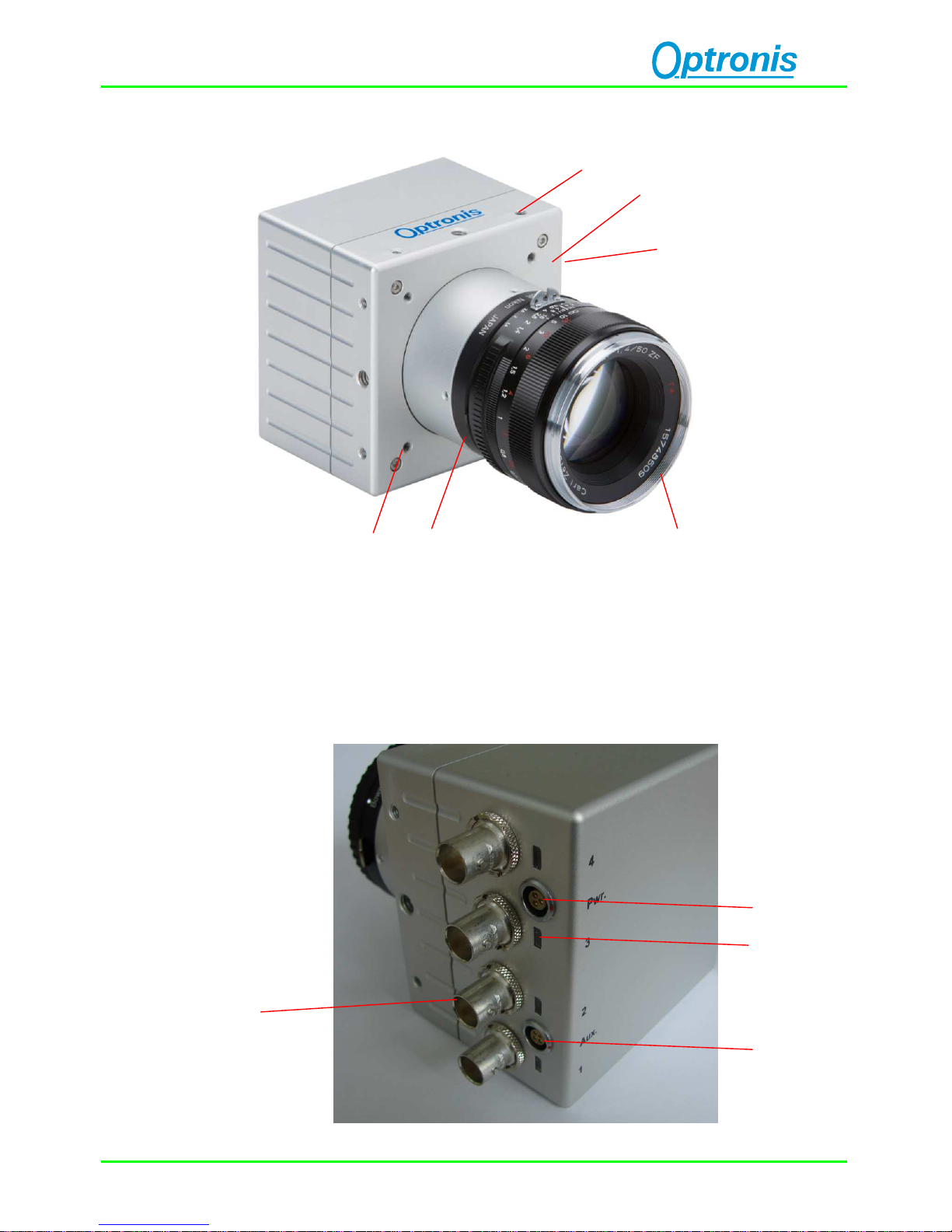
Camera
1: Camera housing 2: Mounting holes 2x M4x6mm 1x ¼ ``x6mm
3: Lens mount (Nikon-F) 4: Nikon lens
5: electrical interface (right side) 6: Mounting holes 4x M4x6mm
1
3
4
5
6
2
4
3
2
1
CP80-25-M/C-72 Ref. 1889-SU-01-D Page 9
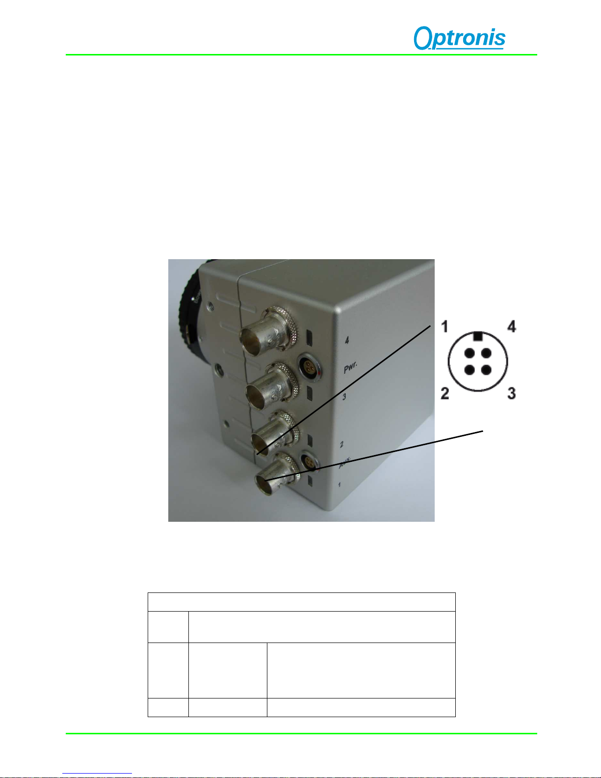
1: CoaxPress Channel 2: Power Connector
3: Auxiliary Connector 4: Indicator Lamp (LED)
Electrical Interface
Auxiliary (Aux.) connector pinout
Auxiliary (Aux.) connector pinout
Pin
Nr.
Description
1 Sync. In
External Synchronisation Input
TTL level: <0,8Volt (low)
> 2 Volt (high)
2 reserved -

CP80-25-M/C-72 Ref. 1889-SU-01-D Page 10
3 GND Sync. Ground
4 Sync. Out
External Synchronisation Output
(TTL level @ high impedance,
0 to 2 Volt @ 50 Ohms )
To operate SyncIn correctly, a SyncIn driver circuit has to be used.
Minimum Sink Current (TTL Low Level) of the SyncIn Driver has to be
5mA. At 5mA Sink Current the input level at the SyncIn camera input
drops below 0,8Volts.
Source Current (TTL High Level).of the SyncIn Driver is neglible (0mA)
Easiest driver circuit is a Transistor working in open collector
configuration.
SyncIn input voltage limit ranges from – 5 Volts to + 30 Volts. Voltages
applied beyond these limits may damage the SyncIn Input.
SyncOut has a built in 50 Ohm driver.
At 50 Ohm termination, the driver voltage is in between 0 (low level) to
~2 Volts (high level). At high impedance termination, the driver voltage
is in between 0 (low level) to ~4 Volts (high level).
SyncOut voltage limit ranges from 0 Volt to + 5 Volts. Voltages applied
beyond these limits may damage the SyncOut Output.
The Auxiliary connector may also be used to update the firmware of the
camera. Please use the USB2 programming adapter cable.
 Loading...