

Page 1
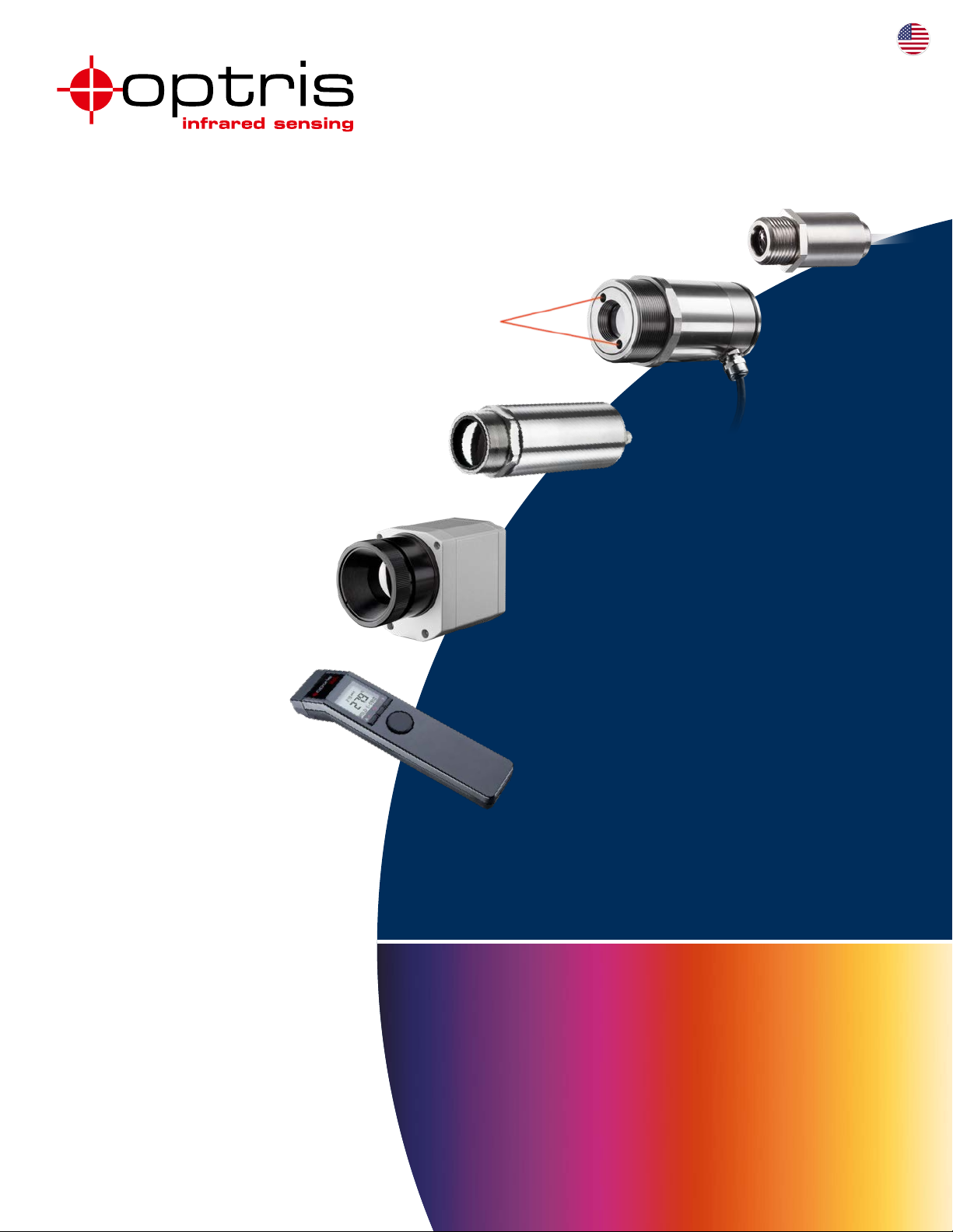
innovative infrared technology
Infrared thermometers
Infrared video thermometers
Infrared cameras
Portable thermometers
PRODUCT OVERVIEW
Non-contact temperature measurement
Page 2
The adequate measurement device
Spot measurement
or thermal image?
First of all, it is important to dene the measurement task and
to decide on one of these two measures:
A point measuring infrared ther-
mometer should be used if you know
where the critical point or the area to
be measured is positioned within your
application. The size of the measuring
object is important to dene which
lens is necessary.
It is therefore possible to monitor the
accurate temperature and optimize
processes – if necessary – before
quality problems arise.
Pyrometer congurator:
www.optris.com/pyrometer-selector
Which object surface?
The condition of the object surface
denes the measurement device
and wavelength to be used for
the application. The emissivity Ɛ
occupies a central position. The
choice of the right device is of great
importance especially for metals,
where the emissivity depends on
the temperature and wave length.
We are able to oer appropriate meas-
urement devices for most applications
throughout a wide product range.
The following explanation helps to
nd the right wavelength for your
application:
[°C]
■ 8 – 14 μm for non-metal surfaces
(Type of device: LT)
■ 0.5; 1.0; 1.6; 2.3 μm mainly for
liquid metals and metal surfaces
(Type of device: 05M; 1M; 2M; 3M)
■ 3.43 µm for thin plastic lms
like PE, PP and PS (Type of
device: P3)
■ 3.9; 4.24; 4.64; 7.9 μm for
special applications (Type of
device: MT; F2; F6)
■ 5.0 μm for glass surfaces
(Type of device: G5)
■ 7.9 μm for plastic foils and glass
surfaces (Type of device: P7/G7)
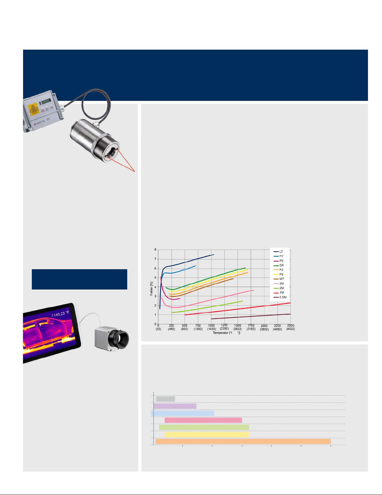
Short wavelengths reduce
measurement errors on
surfaces with low, unknown
or changing emissivity. This
occurs mostly with metals.
The diagram above shows
the measurement errors
across different wavelengths
if the emissivity is wrongly
adjusted by only 10 percent.
Infrared cameras should be used in
cases where more than one critical
area exists or the area cannot be
clearly dened. Critical areas can be
localized by the camera through the
demonstration of thermal images.
The areas can then be permanently
monitored by one or multiple xed
infrared thermometers.
2
Which temperature range?
The temperature is another factor to
decide on. The range should cover
all relevant temperatures of the appli-
µm
50 °C t o 400 °C
0 °C t o 710 °C
–50 °C t o 1030 °C
0 500 1000 1500 2000
Display of temperature over wavelength for the devices of the compact and the high performance series
(122 °F to 752 °F)
(32 °F to 1310 °F)
(–58 °F t o 1886 °F)
200 °C t o 1500 °C
100 °C t o 1650 °C
200 °C t o 1650 °C
50 °C t o 3000 °C
Temperature in °C (°F)
cation. The measurement range of
the devices is between –50 °C and
3000 °C (–58 °F and 5432 °F).
(392 °F to 2732 °F)
(212 °F t o 3002 °F)
(392 °F t o 3002 °F)
(122 °F t o 5432 °F)
2500 3000
P3
P7
LT
G7
G5
MT, F2, F6
05M, 1M, 2M, 3M
(5432) (4532) (3632) (2732) (1832) (932) (32)
Page 3
For further information on non-contact temperature measurement see our brochure on basics
of IR temperature measurement:
www.optris.com/downloads-compact-series
innovative infrared technology
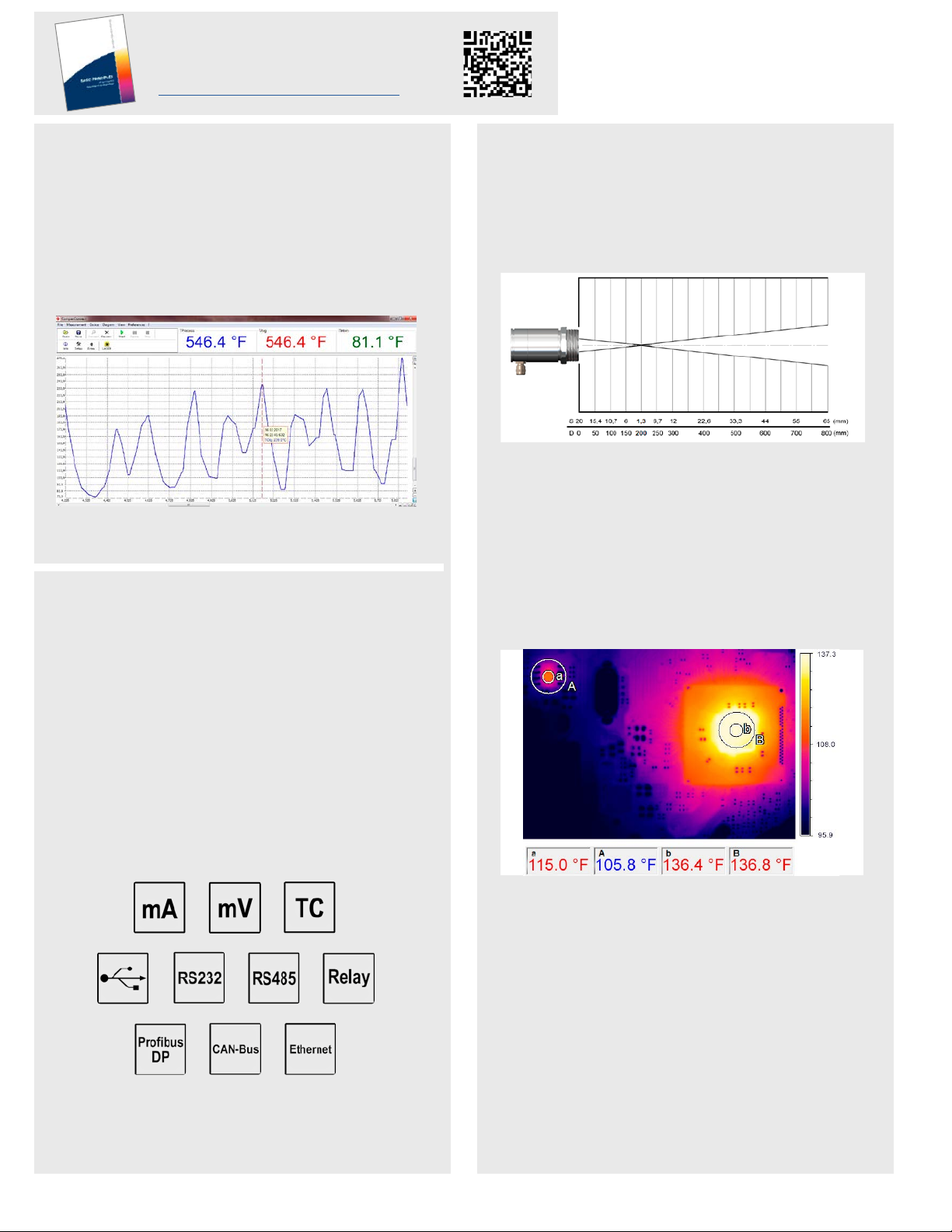
Which process velocity?
To achieve accurate temperature measurement it is
important to know how fast measuring objects are
moving in front of the sensor or how fast they change
temperature.
Our fastest infrared thermometer captures changes
within 1 ms.
Display of fast temperature changes over a period of time.
Integration of sensors?
Our temperature sensors can be installed as part of the
process with mounting brackets or anges.
Object size and measurement distance
IR thermometers use the radiation signal emitted by the
entire measurement spot. The size of the measurement
spot (S) largely depends on the device, the optics
selected and the distance between the sensor and
measurement object plane (D):
Measurement spot diameter (S) depending on the measurement distance
(D) with an IR thermometer
For a precise temperature measurement, the measurement spot needs to be smaller than, or the same size as
the object to be measured.
If the measurement spot is larger than the object, a temperature is calculated from the averaged heat radiation
signal from the object and its environment. In a colder
environment, it means that correspondingly, the temperature measurement value determined is too low.
Depending on the device, we oer dierent analog and
digital interfaces for data evaluation such as triggering,
alerting or saving of data.
Analog Interfaces:
0 – 20 mA, 4 – 20 mA, 0 – 5 V, 0 – 10 V,
Thermocouple (type J, type K)
Digital Interfaces:
USB, RS232, RS485, Relay, Probus DP, CAN Bus,
Ethernet
IR image of an electronics circuit board – adaptation of the measurement
spot to the object size
When transferred to the two-dimensional measurement
with IR cameras, the pixel size there needs to suit the
object size for the selected measurement distance. Here,
the object should ll at least 3 x 3 pixels.
In the example above, the correct temperature of a chip of
46 °C (114.8 °F) is determined with the suitable measure-
ment spot size (a). A measurement spot (A) which is three
times larger already leads to a measurement error of 5 °C
(41 °F) or 10 %. If you select a larger component on the
same circuit board (on the right in the picture), then in this
case, both measurement spots (b and B) provide the correct temperature measurement value of 58 °C (136.4 °F).
3
Page 4

Compact series
Small, compact infrared thermo-
meters, ideal for use in cramped
and hot surroundings
Base Model CS CSmicro CSmicro CSmicro CSmicro CT CTfast CThot CT CT CT CT
Type LT LT02/ LT15(H)/ LT22H
Classication /
special features
Detector
Sensing head exchangeable
Head cable shortening
Thread (sensing head)
Spectral range
Temperature ranges
Single-piece sensor, smart
LED display (self diag
nostics, aiming support,
Single-piece sensor with
-
electronics in cable; smart
LED display
alarm, temp. code)
Thermopile
Thermopile
– – – – – ■ – ■ ■ ■ ■ –
■ ■
(behind electronics)
M12x1 M12x1 M18x1 M12x1 M12x1 M12x1 M12x1 M18x1 M12x1 M12x1 M12x1 M18x1
8 – 14 μm 8 – 14 μm 8 – 14 μm 1.6 μm 2.3 μm 8 – 14 μm 8 – 14 μm 8 – 14 μm 1M: 1.0 μm / 2M: 1.6 μm 2.3 μm 5.0 μm P3: 3.43 µm / P7: 7.9 μm
–40 ... 1030 °C
(–40 ... 1886 °F)
–50 ... 1030 °C
(–58 ... 1886 °F)
LT15 HS
Single-piece two-wire
sensor with electronics in
cable; high thermal sensiti
vity; smart LED display
2M 3M
Single-piece sensor for
temp. measurements on
-
metal; electronics in cable;
smart LED display
Single-piece sensor for
temp. measurements on
metal; electronics in cable;
smart LED display
Thermopile InGaAs Ext. InGaAs Thermopile Thermopile Thermopile 1M: Si / 2M: InGaAs Extended InGaAs Thermopile Thermopile (P7)
■
(behind electronics)
–20 ... 150 °C
(–4 ... 302 °F)
■
(behind electronics)
2ML: 250 ... 800 °C
(2ML: 482 ... 1472 °F)
2MH: 385 ... 1600 °C
(2MH: 725 ... 2912 °F)
■
(behind electronics)
3ML: 50 ... 350 °C
(3ML: 122 ... 662 °F)
3MH: 100 ... 600 °C
(3MH: 212 ... 1112 °F)
Temperature resolution
Optical resolution
Option: CF lens
Smallest spot (CF optics / add. CF lens)
Smallest spot (SF optics)
Sighting
Response time (90 %)
Accuracy
Analog O/P: 0-20 mA/4-20 mA/0-5 V/0-10 V/t/c (K/J)
Second analog output
USB / RS232 / RS485 / Probus / Ethernet
Peak / Valley / AVG / Advanced hold
T
Head min.
Amb
T
Head max.
Amb
T
Electronics max.
Amb
Functional inputs / number
External emissivity adjustment
External background temp. control / Trigger in-
put for reset of hold functions / Digital I/O pins
Simultaneous analog + digital O/P / Alarm O/P
as altern. to analog O/P / Additional alarm O/P
Voltage supply
Standard cable length options
4
0.1 K 0.1 K 0.025 K [>20 °C (>68 °F)] 0.1 K 0.1 K 0.1 K LT15F: 0.2 K / LT25F: 0.4 K 0.25 K 0.1 K 0.1 K L: 0.1 K / H: 0.2 K P3: 0.1 K / P7: 0.5 K
15:1 LT02: 2:1 / LT15 (H): 15:1 /
LT22 H: 22:1
■
0.8 mm @ 10 mm
(0.03 in @ 0.4 in)
■ ■ ■ ■ ■ ■ ■ ■ ■ – –
LT02: 2.5 mm @ 23 mm
(LT02: 0.1 in @ 0.9 in)
LT15 (H): 0.8 mm @ 10 mm
(LT15 (H): 0.03 in @ 0.4 in)
15:1 2ML: 40:1
2MH: 75:1
0.8 mm @ 10 mm
(0.03 in @ 0.4 in)
2MH: 1.5 mm@110 mm
(2MH: 0.06 in @ 4.3 in)
2ML: 2.7 mm@110 mm
(2ML: 0.11 in @ 4.3 in)
3ML: 22:1
3MH: 33:1
3ML: 1.5 mm @ 30 mm
(3ML: 0.06 in @ 1.2 in)
3MH: 1 mm @ 30 mm
(3MH: 0.04 in @ 1.2 in)
LT 22 H: 0.6 mm @ 10 mm
(LT 22 H: 0.02 in @ 0.4 in)
7 mm (0.3 in) 7 mm (0.3 in) 7 mm (0.3 in) 7 mm (0.3 in) 7 mm (0.3 in) 7 mm (0.3 in) 7 mm (0.3 in) 7 mm (0.3 in) 7 mm (0.3 in) 7 mm (0.3 in) 7 mm (0.3 in) 7 mm (0.3 in)
LED aiming LED aiming LED aiming LED aiming LED aiming
25 ms 14 ms 150 ms 150 ms 10 ms 150 ms LT15F: 9 ms / LT25F: 6 ms 100 ms 1 ms 1 ms L: 120 ms / H: 80 ms P3: 100 ms / P7: 150 ms
±1.5 °C or ±1.5 %
(±3.0 °F or ±1.5 %)
– / – / ■ / ■ / ■
±1 °C or ±1 %
(±2 °F or ±1 %)
– / – / ■ / ■ / – or
– /
■ / – / – / –
±1 °C or ±1 %
(±2 °F or ±1 %)
– / – / ■ / ■ / – or
– /
■ / – / – / –
±(0.3 % T
±(0.3 % T
meas
meas
+2 °C)
+4 °F)
– / – / ■ / ■ / – or
– /
■ / – / – / –
±(0.3 % T
±(0.3 % T
meas
meas
+2 °C)
+4 °F)
– / – / ■ / ■ / – or
– /
■ / – / – / –
– – – – – ■ ■ ■ – – ■ ■
■ / – / – / – / – ■ / – / – / – / – ■ / – / – / – / – ■ / – / – / – / – ■ / – / – / – / – ■ / ■ / ■ / ■ / ■ ■ / ■ / ■ / ■ / ■ ■ / ■ / ■ / ■ / ■ ■ / ■ / ■ / ■ / ■ ■ / ■ / ■ / ■ / ■ ■ / ■ / ■ / ■ / ■ ■ / ■ / ■ / ■ / ■
■ / ■ / ■ / ■ ■ / ■ / ■ / ■ ■ / ■ / ■ / ■ ■ / ■ / ■ / ■ ■ / ■ / ■ / ■ ■ / ■ / ■ / ■ ■ / ■ / ■ / ■ ■ / ■ / ■ / ■ ■ / ■ / ■ / ■ ■ / ■ / ■ / ■ ■ / ■ / ■ / ■ ■ / ■ / ■ / ■
–20 °C (–68 °F) –20 °C (–68 °F) –20 °C (–68 °F) –20 °C (–68 °F) –20 °C (–68 °F) –20 °C (–68 °F) –20 °C (–68 °F) –20 °C (–68 °F) –20 °C (–68 °F) –20 °C (–68 °F) –20 °C (–68 °F)
80 °C (176 °F) LT02 / LT15: 120 °C (248 °F)
75 °C (167 °F) 125 °C (257 °F)
LT15H/LT22H: 180°C (356°F)
80 °C (176 °F) 80 °C (176 °F) /
75 °C (167 °F) (mA version)
■
/ 1
■
(via Vcc adjust)
■ / ■ / – ■
■
/ 1
■
(mV version)
(mV version)
/ ■ / – ■
– / ■ / ■ ■ (mA version only) /
■ / ■
80 °C (176 °F) /
75 °C (167 °F) (mA version)
■
/ 1
■
(mV version)
(mV version)
/ ■ / – ■
■ (mA version only) /
■ / ■
80 °C (176 °F) /
75 °C (167 °F) (mA version)
■
/ 1
■
(mV version)
(mV version)
/ ■ / – ■
■ (mA version only) /
■ / ■
80 °C (176 °F) /
75 °C (167 °F) (mA version)
■
/ 1
■
(mV version)
(mV version)
/ ■ / – ■ / ■ / – ■ / ■ / – ■ / ■ / – ■ / ■ / – ■ / ■ / – ■ / ■ / – ■ / ■ / –
■ (mA version only) /
■ / ■
5 – 30 V DC 5 – 30 V DC 5 – 30 V DC 5 – 30 V DC 5 – 30 V DC 8 – 36 V DC 8 – 36 V DC 8 – 36 V DC 8 – 36 V DC 8 – 36 V DC 8 – 36 V DC 8 – 36 V DC
1 / 3 / 8 / 15 m (3.3 / 9.8 /
26.2 / 49.2 ft)
0.5 + 0.5 m / up to 9 m
(1.6 ft / up to 29.5 ft)
0.5 + 0.5 m / up to 9 m
(1.6 ft / up to 29.5 ft)
0.5 + 0.5 m / up to 9 m
(1.6 ft / up to 29.5 ft)
0.5 + 0.5 m / up to 9 m
(1.6 ft / up to 29.5 ft)
Page 5

Spot size calculator: www.optris.com/spot-size-calculator
innovative infrared technology
LT02 / LT15 / LT22
Two-piece sensor with
separate electronic box
incl. display and program
ming keys
■
[–0.1 K/m]
LT02: –50 ... 600 °C
(LT02: –58 ... 1112 °F)
LT15: –50 ... 600 °C
(LT15: –58 ... 1112 °F)
LT22: –50 ... 975 °C
(LT22: –58 ... 1787 °F)
LT02: 2:1 / LT15: 15:1 /
LT22: 22:1
LT15F / LT25F LT02H / LT10H 1M / 2M 3M G5 P3 / P7
Two-piece sensor, fast
response time, separate
-
electronic box incl. display
and programming keys
■
[max. 3 m] (9.8 ft)
–50 ... 975 °C
(–58 ... 1787 °F)
LT15F: 15:1
LT25F: 25:1
Two-piece sensor for hot
surroundings with separate
electronic box incl. display
and programming keys
■
[–0.1 K/m]
–40 ... 975 °C
(–40 ... 1787 °F)
Two-piece sensor for high
temp. meas. of metal, se
parate electronic box incl.
display and progr. keys
■
[max. 3 m] (9.8 ft)
1ML: 485 ... 1050 °C
(1ML: 905 ... 1922 °F)
1MH: 650 ... 1800 °C
(1MH: 1202 ... 3272 °F)
1MH1: 800 ... 2200 °C
(1MH1: 1472 ... 3992 °F)
2ML: 250 ... 800 °C
(2ML: 482 ... 1472 °F)
2MH: 385 ... 1600 °C
(2MH: 725 ... 2912 °F)
2MH1: 490 ... 2000 °C
(2MH1: 914 ... 3632 °F)
LT02H: 2:1
LT10H: 10:1
L: 40:1
H: 75:1
Two-piece sensor for low
-
temp. meas. of metal, se
parate electronic box incl.
display and progr. keys
■ ■
L: 50 ... 400 °C
(L: 122 ... 752 °F)
H: 100 ... 600 °C
(H: 212 ... 1112 °F)
H1: 150 ... 1000 °C
(H1: 302 ... 1832 °F)
H2: 200 ... 1500 °C
(H2: 392 ... 2732 °F)
H3: 250 ... 1800 °C
(H3: 482 ... 3272 °F)
L: 22:1 / H: 33:1 /
H1–H3: 75:1
Two-piece sensor for temp.
-
meas. of glass, separate
electronic box incl. display
and programming keys
[–0.1 K/m]
L: 100 ... 1200 °C
(L: 212 ... 2192 °F)
H: 250 ... 1650 °C
(H: 482 ... 3002 °F)
L: 10:1
H: 20:1
Two-piece sensor for temp.
meas. on thin plastic film /
glass (P7), separate electr.
box incl. display + progr. keys
–
P3: 50 ... 400 °C
(P3: 122 ... 752 °F)
P7: 0 ... 710 °C
(P7: 32 ... 1310 °F)
P3: 15:1
P7: 10:1
LT02: 2.5 mm @ 23 mm
(LT02: 0.1 in @ 0.9 in)
LT15: 0.8 mm @ 10 mm
(LT15: 0.03 in @ 0.4 in)
0.5 mm @ 10 mm
(0.02 in @ 0.4 in)
LT02H: 2.5 mm @ 23 mm
(LT02H: 0.10 in @ 0.9 in)
1.5 mm @ 110 mm
(0.06 in @ 4.3 in)
LT10H: 1.2 mm @ 10 mm
(LT10H: 0.05 in @ 0.4 in)
3.4 mm @ 110 mm
(0.13 in @ 4.3 in)
–
P7: 1.2 mm @ 10 mm
(P7: 0.05 in @ 0.4 in)
LT22: 0.6 mm @ 10 mm
(LT22: 0.02 in @ 0.4 in)
– – – – – – –
±1 °C or ±1 %
(±2 °F or ±1 %)
±2 °C or ±1 %
(±4 °F or ±1 %)
±1.5 °C or ±1 %
(±3.0 °F or ±1 %)
±(0.3 % T
±(0.3 % T
meas
meas
+2 °C)
+4 °F)
±(0.3 % T
±(0.3 % T
meas
meas
+2 °C)
+4 °F)
±2 °C or ±1 %
(±4 °F or ±1 %)
P3: ±3 °C (±5 °F) or 1 %
P7: ±1.5 °C (±3 °F) or 1 %
■ / ■ / ■ / ■ / ■ ■ / ■ / ■ / ■ / ■ ■ / ■ / ■ / ■ / ■ ■ / ■ / ■ / ■ / ■ ■ / ■ / ■ / ■ / ■ ■ / ■ / ■ / ■ / ■ ■ / ■ / ■ / ■ / ■
P3: 0 °C (°F) / P7: –20 °C (–68 °F)
LT02: 130 °C (266 °F)
LT15 / LT22: 180 °C (356°F)
120 °C (248 °F) 250 °C (482 °F) 1M: 100 °C / 2M: 125 °C
(1M: 212 °F / 2M: 257 °F)
85 °C (185 °F) 85 °C (185 °F) 85 °C (185 °F) 85 °C (185 °F) 85 °C (185 °F) 85 °C (185 °F)
85 °C (185 °F) 85 °C (185 °F) P3: 75 °C / P7: 85 °C
(P3: 167 °F / P7: 185 °F)
P3: 75 °C (167 °F) /
P7: 85 °C (185 °F)
■
/ 3
■
/ 3
■
/ 3
■
/ 3
■
/ 3
■
/ 3
■
/ 3
■ ■ ■ ■ ■ ■ ■
■ / ■ / ■ ■ / ■ / ■ ■ / ■ / ■ ■ / ■ / ■ ■ / ■ / ■ ■ / ■ / ■ ■ / ■ / ■
1 / 3 / 8 / 15 m (3.3 / 9.8 /
26.2 / 49.2 ft)
1 / 3 / 8 / 15 m (3.3 / 9.8 /
26.2 / 49.2 ft)
3 / 8 / 15 m (9.8 / 26.2/
49.2 ft)
3 / 8 / 15 m (9.8 / 26.2/
49.2 ft)
3 m (9.8 ft) 3 / 8 / 15 m (9.8 / 26.2/
49.2 ft)
3 / 8 / 15 m (9.8 / 26.2/
49.2 ft)
5
Page 6
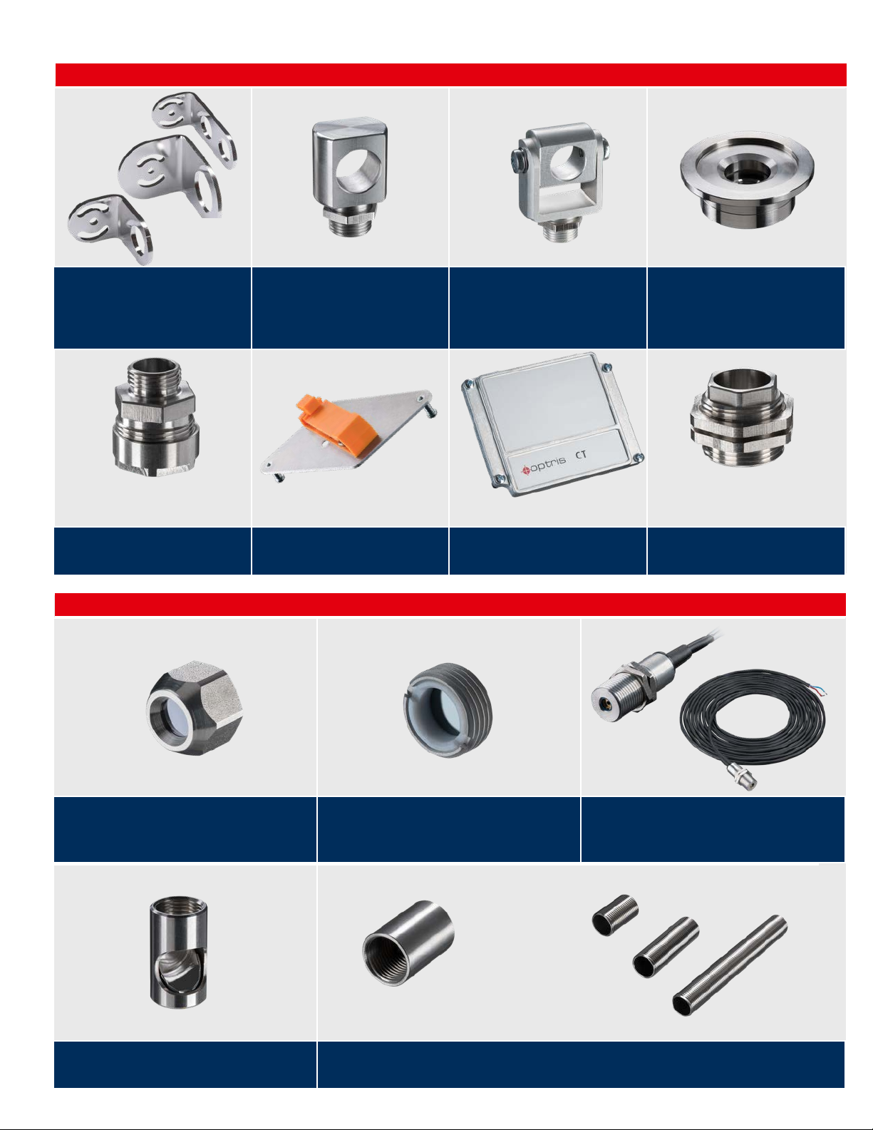
Accessories Compact series
Mechanical accessories
ACCTFB / ACCTFBMH / ACCTFB2
Mounting bracket, adjustable in one axis
(M12x1 sensing head, massive housing,
mounting of CT sensing head + LaserSightingtool)
ACCTTAS
Tilt assembly for heads with optical
resolution ≥10:1
Optical accessories
ACCTMB
Mounting bolt with thread M12x1
ACCTRAIL
Rail mount adapter for CT electronics
ACCTMG
Mounting fork, adjustable in 2 axes, with
thread M12x1
ACCTCOV
Closed cover for CT electronic box
ACCTKF40B270 / ACCTKF40GE
KF40 flange for CT1M, 2M, 3M with B270
window (up to 10-7 mbar) /
KF40 flange for CTLT with Ge window (up
to 10-7 mbar)
ACCTTAM25
Thread adapter M12x1 to M25x1.5 incl.
2 mounting nuts
ACCTCF / ACCTPW
CF-lens or protective window (for LT) for
M12x1 sensing head
ACCTCFHT / ACCTPWHT for 1M, 2M, 3M
ACCTRAM
Right angle mirror for measurements 90° to the sensor
axis for sensing heads with optical resolution ≥10:1
6
ACCTCFE / ACCTPWE
CF-lens or protective window (for LT) with external thread
for air purge or massive housing
ACCTCFHTE / ACCTPWHTE for 1M, 2M, 3M
D08ACCTLST / ACCTOEMLST
Laser-Sightingtool (for CT )/ OEM Laser-Sightingtool,
635 nm, rotation symmetrical, for connection to CT electronics, power supply via CT electronic box or battery
+
ACCTPA + ACCTST20 20 (20 mm length) / ACCTST40 (40 mm length) / ACCTST88 (88 mm length)
Pipe adapter with M12x1 internal thread + Sighting tube with M12x1 external thread
Page 7
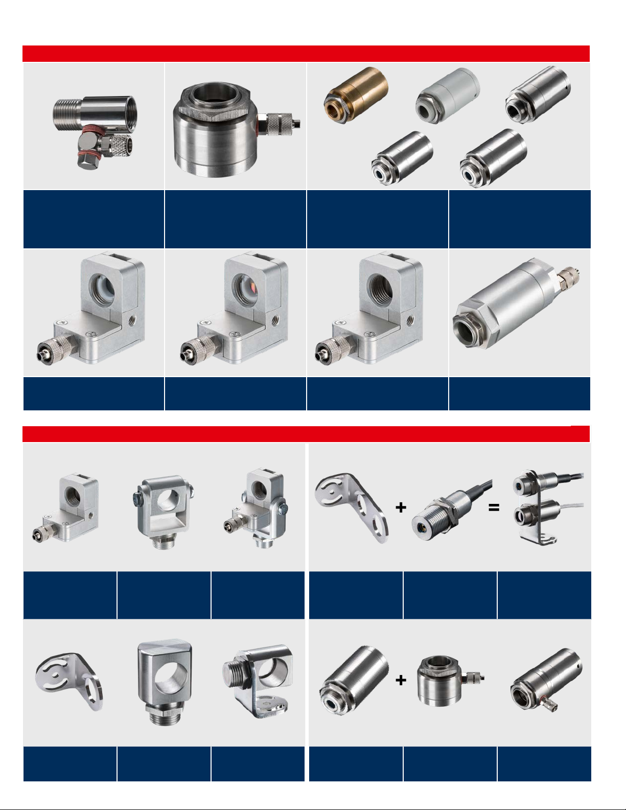
Air purges and protective housings
innovative infrared technology
ACCSAP
Air purge collar (for heads with optical
resolution ≥10:1)
ACCTAPLCF
Air purge collar, laminar, with integrated
CF-lens (for LT)
Combinations
ACCTAPMH
Air purge collar for Massive housing (D06)/
CSmicro HS/ CThot/ CT P3/ CT P7
ACCTAPLCFHT
Air purge collar, laminar, with integrated
CF-lens (for 1M/ 2M/ 3M)
Massive housing of:
• compact, brass (D06ACCTMHB)
• anodized aluminium (D06ACCTMHA)
• stainless steel (D06ACCTMHS)
ACCTAPL
Air purge collar, laminar
• stainless steel version with CF optics
(D06ACCTMHSCF)
• stainless steel version for HT CF optics
(D06ACCTMHSCFHT)
ACCTAP / ACCTAP2
Air purge for CT heads (not for heads with
32 mm length)
ACCTAPL
Air purge collar, laminar
ACCTFB
Mounting bracket for
M12x1 sensing head
+ +
ACCTMG
Mounting fork
+
ACCTMB
Mounting bolt
= =
Device adjustable in two
axes
= =
ACCTAB
Device adjustable in two
axes
ACCTFB2
Mounting bracket for sensing head + Sighting tool
+
D06ACCTAPMH
Massive housing, stainless
steel
D08ACCTLST /
ACCTOEMST
OEM Laser-Sightingtool
ACCTAPMH
Airpurge, stainless steel
Sensing head with LaserSighting tool
Massive housing with air
purge
7
Page 8
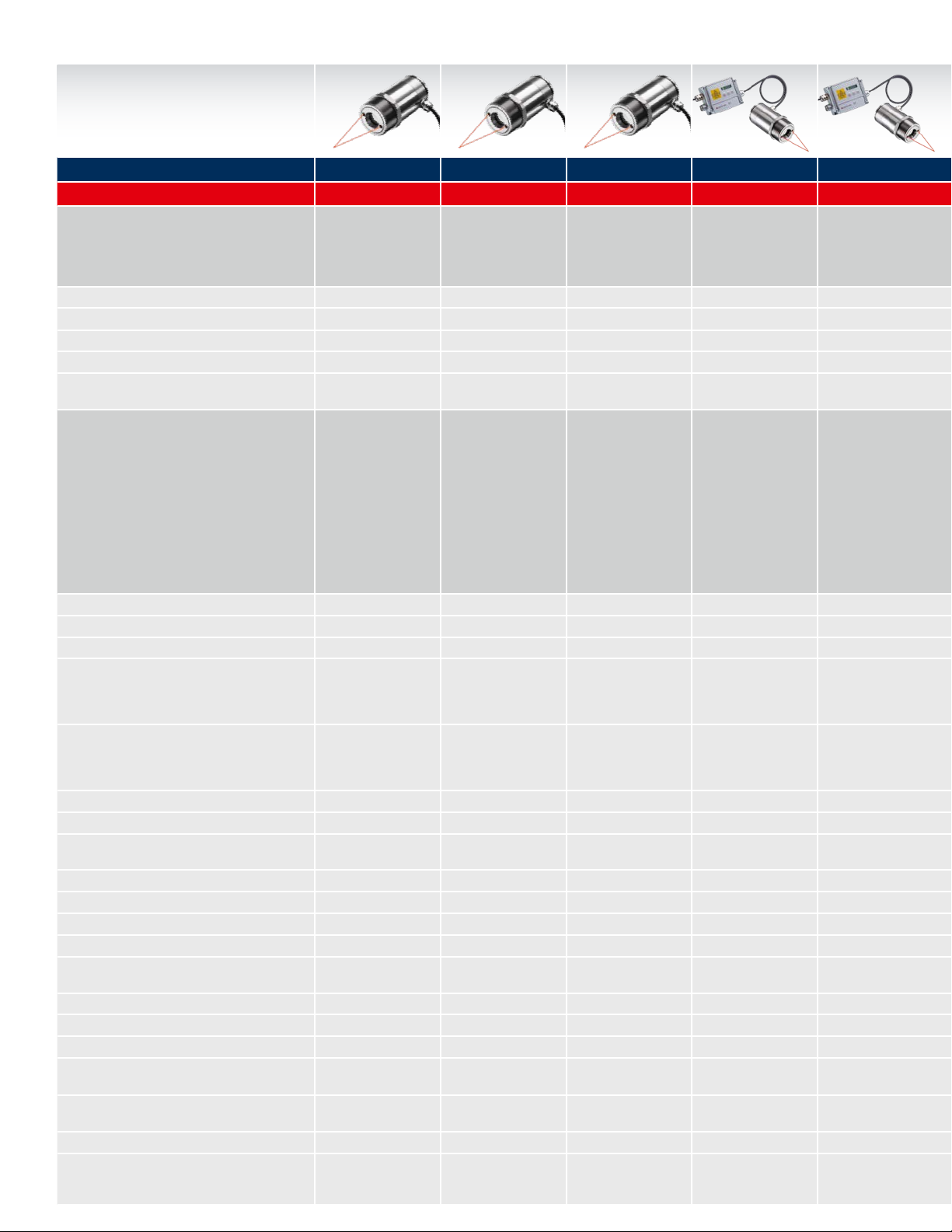
High performance series
Infrared thermometers with
highest optical resolution and
double laser
Base Model CSlaser CSlaser CSlaser CTlaser CTlaser CTlaser CTlaser CT XL CTlaser CTlaser CTlaser CTratio
Type LT / hs LT 2M G5HF LT / LTF 05M 1M / 2M 3M 3M MT / F2 / F6 G5 P7 1M
Classication /
special features
Detector
Sensing head exchangeable
Head cable shortening
Thread (sensing head)
Spectral range
Single-piece two-wire
sensor with electronics in
sensing head
Thermopile
Single-piece two-wire
sensor with electronics
in sensing head for
measurement of metal
InGaAs
Single-piece two-wire
infrared thermometer for
temperature measurement
of glass
Thermopile Thermopile
Two-piece sensor with
separate electronic
box with fast response
time, incl. progr. keys and
display
Two-piece sensor with
separate electronic box for
high temp. meas.of liquid
metal, incl. progr. keys and
display
Si 1M: Si / 2M: InGaAs
– – – ■ ■ ■ ■ – ■ ■ ■ –
■ ■ ■ ■
[max. 6 m] (19.7 ft)
■
[max. 6 m] (19.7 ft)
M48x1.5 M48x1.5 M48x1.5 M48x1.5 M48x1.5 M48x1.5 M48x1.5 M30x1 M48x1.5 M48x1.5 M48x1.5 M18x1
8 – 14 μm 1.6 μm 5.0 μm 8 – 14 μm 0.525 μm 1M: 1.0 μm / 2M: 1.6 μm 2.3 μm 2.3 μm MT: 3.9 μm / F2: 4.24 μm /
Temperature ranges
Temperature resolution
Optical resolution
Option: CF lens
Smallest spot (CF optics / add. CF lens)
Smallest spot (SF optics)
Sighting
Response time (90 %)
Accuracy
Analog O/P: 0-20 mA/4-20 mA/0-5 V/0-10 V/t/c (K/J)
Second analog output
USB / RS232 / RS485 / Probus / Ethernet
Peak / Valley / AVG / Advanced hold
T
Head min. / T
Amb
T
Electronics max.
Amb
Functional inputs / number
External emissivity adjustment
External background temp. control / Trigger in-
put for reset of hold functions / Digital I/O pins
Simultaneous analog + digital O/P / Alarm O/P
as altern. to analog O/P / Additional alarm O/P
Voltage supply
Standard cable length options
Head max.
Amb
8
LT: –30 °C ... 1000 °C
(– °F ... 1832 °F)
hs LT: –20 °C ... 150 °C
(–4 °F ... 302 °F)
L: 250 °C ... 800 °C
(482 °F ... 1472 °F)
H: 385 °C ... 1600 °C
(725 °F ... 2912 °F)
200 °C ... 1650 °C
(392 °F ... 3002 °F)
–50 °C ... 975 °C
(–58 °F ... 1787 °F)
1000 °C ... 2000 °C
(1832 °F ... 3632 °F)
LT: 0.1 K / hs LT: 0.025 K 0.1 K 0.1 K LT: 0.1 K / LTF: 0.5 K 0.2 K 0.1 K 0.1 K 0.1 K 0.1 K L: 0.1 K / H,HF: 0.2 K 0.5 K 0.1 K (> 900 °C) (>1652 °F)
50:1 300:1 45:1 LT: 75:1 / LTF: 50:1 150:1 L: 150:1 / H: 300:1
– – – – – – – – – – – –
1.4 mm @ 70 mm
(0.06 in @ 2.8 in)
0.5 mm @ 150 mm
(?.? in @ 5.9 in)
1.6 mm @ 70 mm
(0.06 in @ 2.8 in)
LT: 0.9 mm @ 70 mm
–
(0.04 in @ 2.8 in)
LTF: 1.4 mm @ 70 mm
(0.06 in @ 2.8 in)
24 mm @ 1200 mm
(0.9 in @ 47.24 in)
3.7 mm @ 1100 mm
(0.02 in @ 43.31 in)
27 mm @ 1200 mm
(1.1 in @ 47.24 in)
LT: 16 mm @ 1200 mm
(LT: 0.6 in @ 47.24 in)
7.3 mm @ 1100 mm
(0.29 in @ 43.31 in)
LTF: 24 mm @ 1200 mm
(LTF: 0.9 in @ 47.24 in)
Double laser Double laser Double laser Double laser Double laser Double laser Double laser
150 ms 10 ms 30 ms LT: 120 ms / LTF: 9 ms 1 ms 1 ms 1 ms 1 ms 10 ms
±1 °C or ±1 %
(±2 °F or ±1 %)
±(0.3 % T
±(0.3 % T
meas
meas
+2 °C)
+4 °F)
±1 °C or ±1 %
(±3 °F or ±1 %)
LT: ±1 °C or ±1 %
LTF: ±1.5 °C or ±1 %
±(0.3 % T
±(0.3 % T
meas
meas
+2 °C)
+4 °F)
– / ■ / – / – / – – / ■ / – / – / – – / ■ / – / – / – ■ / ■ / ■ / ■ / ■ ■ / ■ / ■ / ■ / ■ ■ / ■ / ■ / ■ / ■ ■ / ■ / ■ / ■ / ■ ■ / ■ / ■ / ■ / ■ ■ / ■ / ■ / ■ / ■ ■ / ■ / ■ / ■ / ■ ■ / ■ / ■ / ■ / ■ ■ / ■ / ■ / ■ / –
– – – ■ – – – – ■ ■ ■ –
■ / – / – / – / – ■ / – / – / – / – ■ / – / – / – / – ■ / ■ / ■ / ■ / ■ ■ / ■ / ■ / ■ / ■ ■ / ■ / ■ / ■ / ■ ■ / ■ / ■ / ■ / ■ ■ / ■ / ■ / ■ / ■ ■ / ■ / ■ / ■ / ■ ■ / ■ / ■ / ■ / ■ ■ / ■ / ■ / ■ / ■ – / – / – / – / –
■ / ■ / ■ / ■ ■ / ■ / ■ / ■ ■ / ■ / ■ / ■ ■ / ■ / ■ / ■ ■ / ■ / ■ / ■ ■ / ■ / ■ / ■ ■ / ■ / ■ / ■ ■ / ■ / ■ / ■ ■ / ■ / ■ / ■ ■ / ■ / ■ / ■ ■ / ■ / ■ / ■ ■ / ■ / ■ / ■
–20 °C(68 °F)
/ 85 °C (185 °F)
85 °C
(185 °F)
– / – – / – – / – ■
–20 °C(68 °F)
/ 85 °C (185 °F))
85 °C
(185 °F)
–20 °C(68 °F)
/ 85 °C (185 °F)
85 °C
(185 °F)
–20 °C(68 °F)
/ 85 °C (185 °F)
85 °C
(185 °F)
/ 3
–20 °C(68 °F)
/ 85 °C (185 °F)
85 °C
(185 °F)
■
/ 3
– – – ■ ■ ■ ■ ■ ■ ■ ■ –
– / – / – – / – / – – / – / – ■ / ■ / – ■ / ■ / – ■ / ■ / – ■ / ■ / – ■ / ■ / – ■ / ■ / – ■ / ■ / – ■ / ■ / – – / ■ (via I/O pins)
■ / ■ / ■ ■ / ■ / ■ ■ / ■ / ■ ■ / ■ / ■ ■ / ■ / ■ ■ / ■ / ■ ■ / ■ / ■ ■ / ■ / ■ ■ / ■ / ■ ■ / ■ / ■ ■ / ■ / ■ ■ / ■ / ■ (via I/O pins)
5 – 30 V DC 5 – 30 V DC 5 – 28 V DC 8 – 36 V DC 8 – 36 V DC 8 – 36 V DC 8 – 36 V DC 8 – 36 V DC 8 – 36 V DC 8 – 36 V DC 8 – 36 V DC 8 – 36 V DC
3 / 8 / 15 m (9.8 / 26.2/
49.2 ft)
3 / 8 / 15 m (9.8 / 26.2/
49.2 ft)
3 / 8 / 15 m (9.8 / 26.2/
49.2 ft)
3 / 8 / 15 m (9.8 / 26.2/
49.2 ft)
3 / 8 / 15 m (9.8 / 26.2/
49.2 ft)
Page 9

Spot size calculator: www.optris.com/spot-size-calculator
innovative infrared technology
Two-piece sensor with
separate electronic box
for high temp. meas. of
metal, incl. progr. keys and
display
■
[max. 6 m] (19.7 ft)
1ML: 485 °C ... 1050 °C
(1ML: 905 °F ... 1922 °F)
1MH: 650 °C ... 1800 °C
(1MH: 1202 °F ... 3272°F)
1MH1: 800 °C ... 2200 °C
(1MH1: 1472 °F ... 3982°F)
2ML: 250 °C ... 800 °C
(2ML: 482 °F ... 1472 °F)
2MH: 385 °C ... 1600 °C
(2MH: 725 °F ... 2912 °F)
2MH1: 490 °C ... 2000 °C
(2MH1: 914 °F ... 3632 °F)
Two-piece sensor with
separate electronic box
for low temp. meas. of
metal, incl. progr. keys and
display
Two-piece sensor with
separate electronic box
for laser applications, incl.
progr. keys and display
(no laser)
Two-piece sensor with separ.
electr. box incl. progr. keys
and display for meas.:
MT: through ames / F2: CO2
ame gas / F6: CO ame gas
Two-piece sensor with
separate electronic box for
meas. of glass, incl. progr.
keys and display
Two-piece sensor with
separate electronic box for
meas. of plastic foils, incl.
progr. keys and display
Ratio pyrometer with separate electr. box for high temp.
meas. of metal feat. glass
fiber cable and laser, incl.
progr. keys and display
Extended InGaAs Extended InGaAs Thermopile Thermopile Thermopile Si sandwich
■
[max. 6 m] (19.7 ft)
■ ■
[max. 6 m] (19.7 ft)
■
[max. 6 m] (19.7 ft)
■
[max. 6 m] (19.7 ft)
–
5.0 μm 7.9 μm 0.7 – 1.1 μm
F6: 4.64 μm
L: 50 °C ... 400 °C
(L: 122 °F ... 752°F)
H: 100 °C ... 600 °C
(H: 212 °F ... 1112 °F)
H1: 150 °C ... 1000 °C
(H1: 302 °F ... 1832 °F)
H2: 200 °C ... 1500 °C
(H2: 392 °F ... 2732 °F)
H: 100 °C ... 600 °C
(H: 212 °F ... 1112 °F)
H1: 150 °C ... 1000 °C
(H1: 302 °F ...1832 °F)
H2: 200 °C ... 1500 °C
(H2: 392 °F ... 2732 °F)
H3: 250 °C ... 1800 °C
(H3: 482 °F ... 3272 °F)
200 °C ... 1650 °C
(392 °F ... 3002 °F)
L: 100 °C ... 1200 °C
(L: 212 °F ... 2192 °F)
H: 250 °C ... 1650 °C
(H:482 °F ... 2912 °F)
HF: 200 °C ... 1650 °C
(HF: 392 °F ... 2912 °F)
0 °C ... 710 °C
(–32 °F ... 1310 °F)
700 °C ... 1800 °C
(1292 °F ... 3272 °F)
H3: 250 °C ... 1800 °C
(H3: 482 °F ... 3272 °F)
L: 60:1 / H: 100:1 / H1-H3: 300:1
H: 100:1 / H1-H3: 300:1 45:1 L/HF: 45:1 / H: 70:1 45:1 40:1
0.5 mm @ 150 mm
(0.02 in @ 5.9 in)
3.7 mm @ 1100 mm
(0.15 in @ 43.31 in)
±(0.3 % T
±(0.3 % T
meas
meas
+2 °C)
+4 °F)
–20 °C(68 °F)
/ 85 °C (185 °F)
85 °C
(185 °F)
■
/ 3
0.5 mm @ 150 mm
(0.02 in @ 5.9 in)
11 mm @ 1100 mm
(0.4 in @ 43.31 in)
±(0.3 % T
±(0.3 % T
meas
meas
+2 °C)
+4 °F)
–20 °C(68 °F)
/ 85 °C (185 °F)
85 °C
(185 °F)
■
/ 3
0.5 mm @ 150 mm
(0.02 in @ 5.9 in)
11 mm @ 1100 mm
(0.4 in @ 43.31 in)
–
±(0.3 % T
±(0.3 % T
meas
meas
+2 °C)
+4 °F)
–20 °C(68 °F)
/ 85 °C (185 °F)
85 °C
(185 °F)
■
/ 3
1.6 mm @ 70 mm
(0.06 in @ 2.8 in)
27 mm @ 1200 mm
(1.1 in @ 47.24 in)
1 mm @ 70 mm
(0.04 in @ 2.8 in)
17 mm @ 1200 mm
(0.7 in @ 47.24 in)
1.6 mm @ 70 mm
(0.06 in @ 2.8 in)
27 mm @ 1200 mm
(1.1 in @ 47.24 in)
7.7 mm @ 305 mm
(0.3 in @ 12.01 in)
31.3 mm @ 1143 mm
(1.2 in @ 45 in)
Double laser Double laser Double laser Laser
±1.5 °C or ±1 %
(±3 °F or ±1 %)
–20 °C(68 °F)
/ 85 °C (185 °F)
85 °C
(185 °F)
■
/ 3
L: 120 ms / H: 80 ms / HF: 10 ms
±1.5 °C or ±1 %
(±3 °F or ±1 %)
–20 °C(68 °F)
/ 85 °C (185 °F))
85 °C
(185 °F)
■
/ 3
150 ms 5 ms
±1.5 °C or ±1 %
(±3 °F or ±1 %)
–20 °C(68 °F)
/ 85 °C (185 °F)
85 °C
(185 °F)
■
/ 3
±(0.5 % T
±(0.5 % T
–20 °C(68 °F)
/ 85 °C (185 °F)
85 °C
– / –
meas
meas
(185 °F)
+1 °C)
+2 °F)
/
■ (2)
3 / 8 / 15 m (9.8 / 26.2/
49.2 ft)
3 / 8 / 15 m (9.8 / 26.2/
49.2 ft)
–
3 / 8 / 15 m (9.8 / 26.2/
49.2 ft)
3 / 8 / 15 m (9.8 / 26.2/
49.2 ft)
3 / 8 / 15 m (9.8 / 26.2/
49.2 ft)
3 / 6 / 10 / 15 / 22 m
(9.8/ 19.7 / 32.8/ 49.2 /
72.2 ft)
9
Page 10

Infrared video thermometers
Infrared video thermometers
with vario focus and patented
cross hair laser
Base Modell CSvideo CTvideo CTvideo
Type 2M (L / H) 1M / 2M (L / H) 3M (L / H)
Classication /
special features
Detector
Sensing head exchangeable
Head cable shortening
Thread (sensing head)
Spectral range
Temperature ranges
(scalable via software)
Temperature resolution
Optical resolution
Smallest spot (CF optics)
CF vario optics: focusable from
90 mm to 250 mm (0.02 in to 9.8 in)
Smallest spot (SF optics)
SF vario optics: focusable from
200 mm (7.9 ft) to innity
Sighting
Response time (90 %)
Accuracy
Outputs analog: 0 – 20 mA /
4 – 20 mA / 0 – 5 V / 0 – 10 V / t/c (K/J)
USB / RS232 / RS485 / Probus / Ethernet
Peak / Valley / AVG / Advanced hold
T
Head min. / T
Amb
T
Electronics max.
Amb
Functional inputs / number
External emissivity adjustment
External background temp. control
Trigger input for reset of hold functions
Simultaneous analog and digital output
Alarm O/P as an alternative to analog O/P
Additional alarm output
Voltage supply
Standard cable length
Cable length options
1)
Specifications available for object temperatures ≥ lower measurement range 50 °F
Head max.
Amb
Single-piece two wire sensor with electronics in
sensing head, video camera and cross hair laser
for measuring metal
Two-piece sensor with electronic box for high
temperature measurement of metals, video
camera and cross hair laser
Two-piece sensor with electronic box for low
temperature measurement of metals, video
camera and cross hair laser
InGaAs 1M: Si / 2M: InGaAs Extended InGaAs
–
■
[+CT 1M / 2M] [+CT 3M]
[max. 6 m] (19.7 ft) [max. 6 m] (19.7 ft)
M48x1.5 M48x1.5 M48x1.5
1.6 μm 1M: 1.0 μm / 2M: 1.6 μm 2.3 μm
250 °C ... 800 °C (2ML) (482 °F ... 1472 °F)
385 °C ... 1600 °C (2MH) (725 °F ... 2912 °F)
485 °C ... 1050 °C (1ML) (905 °F ... 1922 °F)
650 °C ... 1800 °C (1MH) (1202 °F ... 3272 °F)
800 °C ... 2200 °C (1MH1) (1472 °F ... 3992 °F)
250 °C ... 800 °C (2ML) (482 °F ... 1472 °F)
385 °C ... 1600 °C (2MH) (725 °F ... 2912 °F)
50 °C ... 400 °C (3ML) (122 °F ... 752 °F)
100 °C ... 600 °C (3MH) (212 °F ... 1112 °F)
150 °C ... 1000 °C (3MH1) (302 °F ... 1832 °F)
200 °C ... 1500 °C (3MH2) (392 °F ... 2732 °F)
250 °C ... 1800 °C (3MH3) (482 °F ... 3272 °F)
490 °C ... 2000 °C (2MH1) (914 °F ... 3632 °F)
0.1 K ML: 0.1 K / MH: 0.2 K 0.1 K
2MH: 300:1 / 2ML: 150:1 L: 150:1 / H: 300:1 L: 60:1 / H: 100:1 / H1 – H3: 300:1
2ML: 0.6 mm @ 90 mm (CF) (0.02 in @ 3.5 in)
2MH: 0.3 mm @ 90 mm (CF) (0.01 in @ 3.5 in)
2ML: 1.3 mm @ 200 mm (SF) (0.05 in @ 7.9 in)
2MH: 0.7 mm @ 200 mm (SF) (0.03 in @ 7.9 in)
1ML/2ML: 0.6 mm @ 90 mm (CF)
(0.02 in @ 3.5 in)
1MH-H1/ 2MH-H1: 0.3 mm @ 90 mm (CF)
(0.01 in @ 3.5 in)
1ML/2ML: 1.3 mm @ 200 mm (SF)
(0.05 in @ 7.9 in)
1MH-H1/ 2MH-H1: 0.7 mm @ 200 mm (SF)
(0.03 in @ 7.9 in)
3ML: 1.5 mm @ 90 mm (CF) (0.06 in @ 3.5 in)
3MH: 0.9 mm @ 90 mm (CF) (0.04 in @ 3.5 in)
3MH1 – H3: 0.3 mm @ 90 mm (CF)
(0.01 in @ 3.5 in)
3MH: 3.3 mm @ 200 mm (SF) (0.13 in @ 7.9 in)
3MH: 2.0 mm @ 200 mm (SF) (0.08 in @ 7.9 in)
3MH1 – H3: 0.7 mm @ 200 mm (SF)
(0.03 in @ 7.9 in)
video camera and cross hair laser video camera and cross hair laser video camera and cross hair laser
10 ms 1 ms 1 ms
±(0.3 % T
+2 °C) ±(0.3 % T
meas
+4 °F) ±(0.3 % T
meas
+2 °C) ±(0.3 % T
meas
+4 °F) ±(0.3 % T
meas
– / ■ / – / – / – ■ / ■ / ■ / ■ / ■ ■ / ■ / ■ / ■ / ■
■ / – / – / – / ■ ■ / – / – / – / ■ ■ / – / – / – / ■
■ / ■ / ■ / ■ ■ / ■ / ■ / ■ ■ / ■ / ■ / ■
–20 °C (–4 °F) / 70 °C (158 °F) –20 °C (–4 °F) / 85 °C (185 °F) –20 °C (–4 °F) / 85 °C (185 °F)
70 °C (158 °F) 85 °C (185 °F) 85 °C (185 °F)
– / – ■
/ 3
■
/ 3
– ■ ■
– ■ ■
– ■ ■
■ ■ ■
■ ■ ■
0 – 30 V / 500 mA (open-collector) 24 V / 50 mA (open-collector) 24 V / 50 mA (open-collector)
5 – 28 V DC 8 – 36 V DC 8 – 36 V DC
3 m (9.8 ft) 3 m (9.8 ft) 3 m (9.8 ft)
8 / 15 m (26.2 / 49.2 ft) 5 / 10 m (16.4 / 32.8 ft) 5 / 10 m (16.4 / 32.8 ft)
+2 °C) ±(0.3 % T
meas
meas
1)
1)
1)
+4 °F)
10
Page 11

Software included
Connection options for CSvideo 2M
innovative infrared technology
• Automatic snapshots (time or temperature dependent)
to control and document the process
• Graphic display and recording of the measurement
values
• Setup of sensor parameters and signal processing
functions
• Remote control of the sensor
Analog operation mode: 4 – 20 mA and
alarm interface. Setup & installation
via USB cable (hot Plug & Play)
Connection options for CTvideo 1M / 2M / 3M
standard version
24 – 48 V DC or
Power over Ethernet
Digital operation mode: process control
(video and temperature) via software
PoE
high temperature version
24 – 48 V DC or
Power over Ethernet
PoE
11
Page 12

Accessories High performance series
Mechanical accessories
ACCTLFB
Mounting bracket, adjustable in one axis
ACHAMA
Mounting adapter: Mounting and pipe
flange
Air purges and cooling units
ACCTLAB
Mounting bracket, adjustable in two axes
ACCTCOV
Closed cover for CT electronic box
ACCJAB
Mounting bracket for CoolingJacket, adjustable in two axes
ACCTRAIL
Rail mount adapter for CT electronics
ACCTXLAB
Mounting bracket CT XL, adjustable in
two axes
ACCTLTA20UN
Thread adapter M48x1,5 to 20 UN-2A
thread incl. mounting nut
ACCTAPMH
Air purge collar CTratio
ACCTLCJ
CoolingJacket (stainless steel) for CSlaser/ CTlaser/ CSvideo/ CTvideo
ACCTLAP
Air purge collar CxL/ CxV
12
ACCTXLAP
Air purge collar CT XL
ACCTLW
Water cooled housing CxL/ CxV, stainless steel, for
T
up to 175 °C
amb
Page 13

Optical accessories
innovative infrared technology
ACHAST300 + ACHAPA
Sighting tube M48x1,5, 300 mm length +
pipe adapter with M48x1,5 internal thread
Combinations
+
CT electronic box ACCTRAIL
Rail mount adapter
+
ACCJAFUxx + ACCJAPWPI2xxLW /
ACCJAFUxx + ACCJAPWCTLSW
Focussing unit with protective window for CoolingJacket
=
Electronic box on rail mount
adapter
ACHAMA
Mounting adapter
=
ACCJAFUxx + ACCJAPGMS 2 or 3
Focussing unit with protective grid for CoolingJacket
Advanced
+
ACHAST300 / ACHAPA
Sighting tube / pipe adapter
+
=
ACCTLRM
Furnace wall mount for
CSlaser/ CTlaser
=
CT electronic box ACCTCOV
Closed cover for
CT electronic box
ACCTLCJA
CoolingJacket Advanced
Closed CT electronic box
ACCTLAP
Air purge
+ =
ACCJAAPLS
Air purge laminar for CoolingJacket Advanced
ACCTLW
Water cooled housing
CoolingJacket Advanced with air purge laminar
Cooling sensing head
+ purging of optics
13
Page 14

Portable thermometers
High-quality infrared
thermometers with
integrated USB
interface
Base Model P20 P20 MS MSPlus MSPro
Type LT 1M / 2M / 05M LT LT LT
Detector
Spectral range
Temperature ranges
Temperature resolution
Optical resolution
Smallest spot (SF optics)
Sighting
Response time (90 %)
Accuracy
(at T
23 ±5 °F)
Amb
PC interface / Software
Probe connection (t/c)
T
Min. / Max.
Amb
Display MAX / MIN / HOLD
HIGH / LOW alarm
Data logger / capacity
Emissivity
Thermopile Si / InGaAs Thermopile Thermopile Thermopile
8 – 14 μm 1M: 1.0 μm / 2M: 1.6 μm /
0 °C ... 1300 °C
(32°F ... 2372 °F)
1 K 1 K 0.2 K 0.1 K 0.1 K
120:1 1M / 2M: 300:1 / 05M: 150:1 20:1 20:1 40:1
100 mm @ 12 m
(3.94 in @ 39.4 ft)
Double laser Double laser Laser Laser Laser
300 ms 100 ms 300 ms 300 ms 300 ms
±2 °C or ±1 %
(±4 °F or ±1 %)
USB /
■
– – – – ■
0 °C / 50 °C
(32 °F / 122 °F)
■ ■ ■ ■ ■
■ ■ – ■ ■
■
/ 2000
0.100 ... 1.100 0.100 ... 1.100 0.95 fixed 0.100 ... 1.100 0.100 ... 1.100
05M: 525 nm
1M: 650 °C ... 1800 °C
(1M: 1202 °F ... 3272 °F)
2M: 385 °C ... 1600 °C
(2M: 725 °F ... 2912 °F)
05M: 1000 °C ... 2000 °C
(05M: 1832 °F ... 3632 °F)
1M / 2M: 12 mm @ 3.6 m
(1M / 2M: 0.47 in @ 11.8 ft)
05M: 24 mm @ 3.6 m
(05M: 0.94 in @ 11.8 ft)
±(0.3 % T
±(1 % T
USB /
0 °C / 50 °C
(32 °F / 122 °F)
■
/ 2000
+2 °C)
meas
+4 °F)
meas
■
8 – 14 μm 8 – 14 μm 8 – 14 μm
–32 °C ... 420 °C
(–26 °F ... 788°F)
13 mm @ 140 mm
(0.51 in @ 5.51 in)
±1 °C or ±1 %
(±2 °F or ±1 %)
USB /
0 °C / 50 °C
(32 °F / 122 °F)
– – ■
■
–32 °C ... 530 °C
(–26 °F ... 986 °F)
13 mm @ 140 mm
(0.51 in @ 5.51 in)
±1 °C or ±1 %
(±2 °F or ±1 %)
USB /
0 °C / 50 °C
(32 °F / 122 °F)
■
–32 °C ... 760 °C
(–26 °F ... 1400 °F)
13 mm @ 260 mm
(0.51 in @ 10.2 in)
±1 °C or ±1 %
(±2 °F or ±1 %)
USB /
0 °C / 50 °C
(32 °F / 122 °F)
/ 20
■
Best optics for portable thermometers
The optics of the portable P20 thermometers are designed for
mean as well as long distances. The optris
laser and aiming scope for accurate sighting so that even
more distant objects can be measured precisely.
High optical resolution of 120:1 to 300:1
14
®
P20 has a target
Smallest measuring spot:
100 mm @ 12 m (3.94 in @ 39.4 ft)
Smallest measuring spot:
12 mm @ 3.6 m (0.47 in @ 11.8 ft)
Page 15

optris® Xi Infrared cameras
innovative infrared technology
– The Compact Line
Compact spot nder IR camera
for applications in rough industrial environments
Optics calculator: www.optris.com/optics-calculator
New
Basic model Xi 80 Xi 400
Type IR IR
Detector FPA, uncooled (34 µm pitch) FPA, uncooled (17 µm pitch)
Optical resolution 80 x 80 pixels 382 x 288 pixels
Spectral range 7.5 – 13 μm 7.5 – 13 μm
Temperature ranges –20 ... 100 °C (–4 to 212°F)
Frame rate 50 Hz 80 Hz / 27 Hz
Optics (FOV) 30° (f = 5.1 mm [0.20 in])
0 ... 250 °C (32 to 482 °F)
(20) 150 ... 900 °C
12° (f = 12.7 mm [0.50 in])
55° (f = 3.1 mm [0.12 in])
80° (f = 2.3 mm [0.09])
1)
(302 ... 1652 °F1))
–20 ... 100 °C (–4 to 212°F)
0 ... 250 °C (32 to 482 °F)
(20) 150 ... 900 °C1) (302 ... 1652 °F1))
29° x 22° (f = 12.7 mm [0.50 in])
18° x 14° (f = 20 mm [0.79 in])
53° x 38° (f = 7.7 mm [0.30 in])
80° x 54° (f = 5.7 mm [0.22 in])
New
Macro optics – 18° x 14° (f = 20 mm [0.79 in]), smallest measuring spot: 90 µm)
Focus Manual motor focus Manual motor focus
Optische Auösung (D:S) 190:1 (12° optics) 390:1 (18° optics)
Thermal sensitivity (NETD) 100 mK 80 mK
Accuracy ±2 °C (±3.6 °F) or ±2 %, whichever is greater ±2 °C (±3.6 °F) or ±2 %, whichever is greater
PC interfaces
Direct in-/outputs /
Standard process interface (PIF)
Industral process interface (PIF) 3x 0/4 – 20 mA or 0–10 V outputs,
Cable length (USB) USB: 1 m (standard), 3 m (9.8 ft), 5 m (16.4 ft), 10 m (32.8 ft) and
Ambient temperature
Size / class Ø 36 x 90 mm (1.41 x 3.54 in) (M30x1 thread) / IP 67 (NEMA 4) Ø 36 x 100 mm (1.41 x 3.94 in) (M30x1 thread) / IP 67 (NEMA 4)
Weight 185 g (6.53 oz) 200 g (7.05 oz)
Shock/ Vibration
Power supply USB / PoE / 5-30 VDC via USB
Scope of supply (standard) • Xi camera
3)
USB 2.0 / Ethernet (100 Mbit/s) / PoE / RS 485
1x 0/4–20 mA output
1x input (analog or digital)
Optically isolated
3x input (analog or digital),
3x relays (0 – 30 V) / 400 mA),
1x fail-safe relay; stackable up to 3 PIFs; optically isolated
20 m (65.6 ft)
Ethernet / RS485: 100 m
0 ... 50 °C (41 ... 122 °F) 0 ... 50 °C (41 ... 122 °F)
IEC 60068-2 IEC 60068-2
• USB cable (1 m)
• Cable for in-/outputs (1 m) with terminal block
• Mounting bracket with tripod thread, mounting nut
• Software package optris
• Quick start guide
®
PIX Connect
2)
USB 2. 0 / optional USB to GigE (PoE) interface
1x 0–10 V input
1x digital input (max. 24 V)
1x 0–10 V output
2 x 0–10 V inputs, 1x digital input (max. 24 V)
3 x 0–10 V outputs,
3 x relays (0–30 V / 400 mA),
1x fail-safe relay
USB: 1 m (standard), 3 m (9.8 ft), 5 m (16.4 ft), 10 m (32.8 ft) and
20 m (65.6 ft)
• Xi camera
• USB cable (1 m)
• Cable for in-/outputs (1 m) with terminal block
• Mounting bracket with tripod thread, mounting nut
• Software package optris® PIX Connect
• Quick start guide
1)
Accuracy effective starting at 150 °C (302 °D)
3)
For further details see operator‘s manual
2)
Direct in- and outputs are not available while using the RS485 interface
15
Page 16

optris® PI infrared cameras
- The Precision Line
Compact infrared cameras for
fast online applications, including linescanner
Basic model PI 160 PI 200 / PI 230 PI 400i / PI 450i PI 640
Type IR BI-SPECTRAL IR IR IR IR
Detector FPA, uncooled (25 μm pitch) FPA, uncooled (25 μm pitch) FPA, uncooled (17 μm x 17 μm) FPA, uncooled (17 µm pitch) FPA, (25 µm pitch) FPA, (17 µm pitch)
Optical resolution 160 x 120 pixels 160 x 120 pixels 382 x 288 pixels 640 x 480 pixels VGA 382 x 288 pixels @ 80 Hz
Spectral range 8 – 14 μm 8 – 14 μm 8 – 14 μm 8 – 14 μm 8 – 14 μm 8 – 14 μm
Temperature ranges –20 ... 100 °C (–4 ... 212°F)
(20) 150 ... 900 °C (302 ... 1652 °F)
200 ... 1500 °C (392 ... 2732 °F) (option)
Frame rate 120 Hz 128 Hz
1)
–20 ... 100 °C (–4 ... 212°F)
(20) 150 ... 900 °C (302 ... 1652 °F)
2)
200 ... 1500 °C (392 ... 2732 °F) (option)
4)
1)
–20 ... 100 °C (–4 ... 212°F)
(20) 150 ... 900 °C (302 ... 1652 °F)
2)
200 ... 1500 °C (392 ... 2732 °F) (option)
80 Hz / switchable to 27 Hz 32 Hz / 125 Hz in subframe mode
1)
2)
Optics (FOV) 23° x 17° / f = 10 mm (0.9 in) or
Thermal sensitivity (NETD) 40 mK with 23° x 17° FOV / F = 0.8
Option visual camera (BI-SPECTRAL camera only)
Accuracy ±2 °C (±3.6 °F) or ±2 %, whichever is
PC interfaces
Process
interface
(PIF)
Ambient temperature (T
Storage temperature – 40 ... 70 °C (–40 ... 158 °F) – 40 ... 70 °C (–40 ... 158 °F) PI 400i: – 40 ... 70 °C (–40 ... 158 °F)
Relative Humidity 20 – 80 %, non-condensing 20 – 80 %, non-condensing 20 – 80 %, non-condensing 20 – 80 %, non-condensing 20 – 80 %, non-condensing 20 – 80 %, non-condensing
Size / class 45 (1.77) x 45 (1.77) x 60 – 76 mm
Weight 195 g (6.9 oz), incl. lens 215 g (7.6 oz), incl. lens 195 g (6.88 oz), incl. lens 320 g (11.3 oz), incl. lens 370 g, (13.1 oz), incl. lens 370 g, (13.1 oz), incl. lens
Shock/ Vibration IEC 60068-2 IEC 60068-2 IEC 60068-2 IEC 60068-2 IEC 60068-2 IEC 60068-2
Tripod mount 1/4-20 UNC 1/4 - 20 UNC 1/4 - 20 UNC 1/4 - 20 UNC 1/4 - 20 UNC 1/4 - 20 UNC
Power supply via USB via USB via USB via USB via USB via USB
Scope of supply (standard) • USB camera with 1 lens
Standard PIF 1x 0 – 10 V input, 1x digital input
Industrial PIF
(optional)
) 0 ... 50 °C (32 ... 122 °F) 0 ... 50 °C (32 ... 122 °F) PI 400i: 0 ... 50 °C (32 ... 122 °F) /
Amb
6° x 5° / f = 35.5 mm (1.4 in) or
41° x 31° / f = 5.7 mm (0.2 in) or
72° x 52° / f = 3.3 mm (0.13 in)
0.3 K with 6° x 5° FOV / F = 1.6
0.1 K with 41° x 31° FOV and
72° x 52° FOV / F = 1
– Optical resolution: 640 x 480 pixels
greater
USB 2. 0 / optional USB to GigE (PoE) Interface USB 2.0 / optional USB to GigE (PoE) Interface USB 2.0 / optional USB to GigE (PoE) Interface US B 2.0 / optional USB to GigE (PoE) Interface USB 2 .0 / optional USB to GigE (PoE) Interface
(max. 24 V), 1x 0 – 10 V output
2 x 0 – 10 V inputs, 1x digital input
(max. 24 V), 3 x 0 – 10 V outputs,
3 x relays (0 – 30 V / 400 mA), 1x fail-safe relay
(2.36 - 2.99 in) (depending on lens and focus
position) / IP 67 (NEMA 4)
• USB cable (1 m)
• Table tripod
• PIF cable with terminal block (1 m)
• Manual
• Software package optris® PIX Connect
• Aluminum case
23° x 17° / f = 10 mm (0.9 in) or
6° x 5° / f = 35.5 mm (1.4 in) or
41° x 31° / f = 5.7 mm (0.2 in) or
72° x 52° / f = 3.3 mm (0.13 in)
40 mK with 23° x 17° FOV / F = 0.8
0.3 K with 6° x 5° FOV / F = 1.6
0.1 K with 41° x 31° FOV and
72° x 52° FOV / F = 1
Frame rate: 32 Hz
Optics (FOV): PI 200: 54° x 40°,
PI 230: 30° x 23°
±2 °C (±3.6 °F) or ±2 %, whichever is
greater
1x 0 – 10 V input, 1x digital input
(max. 24 V), 1x 0 – 10 V output
2 x 0 – 10 V inputs, 1x digital input
(max. 24 V), 3 x 0 – 10 V outputs,
3 x relays (0 – 30 V / 400 mA), 1x fail-safe relay
45 (1.77) x 45 (1.77) x 60 – 76 mm
(2.36 - 2.99 in) (depending on lens and focus
position) / IP 67 (NEMA 4)
• USB camera with 1 lens and
BI-SPECTRAL technology
• USB cable (1 m)
• Table tripod
• Focussing tool
• PIF cable with terminal block (1 m)
• Manual
• Software package optris® PIX Connect
• Aluminum case
4)
18° x 14° / f = 20 mm (f = 1.6 in) or
29° x 22° / f = 12.7 mm (f = 0.7 in) or
53° x 38° / f = 7.7 mm (f = 0.4 in) or
80° x 54° / f = 5.7 mm (f = 0.3 in)
PI 400i: 80 mK with 29°, 53°, 80° FOV
PI 450i: 40 mK with 29°, 53°, 80° FOV optics
mentioned above: F = 0.9
PI 400i: 0.1 K with 18° FOV / F = 1.1
PI 450i: 0.06 K with 18° FOV / F = 1.1
– – – –
±2 °C (±3.6 °F) or ±2 %, whichever is
greater
1x 0 – 10 V input, 1x digital input
(max. 24 V), 1x 0 – 10 V output
2 x 0 – 10 V inputs, 1x digital input
(max. 24 V), 3 x 0 – 10 V outputs,
3 x relays (0 – 30 V / 400 mA), 1x fail-safe relay
PI 450i: 0 ... 70 °C (32 ... 158 °F)
PI 450i: – 40 ... 85 °C (–40 ... 185 °F)
45 x 45 x 60 – 75 mm (1.8 x 1.8 x 2.3 - 2.95
in) (depending on lens and focus position)/ IP
67 (NEMA 4)
• USB camera with 1 lens
• USB cable (1 m)
• Table tripod
• PIF cable with terminal block (1 m)
• Manual
• Software package optris® PIX Connect
• Aluminum case (PI 400i)
• Robust hard shell case (PI 450i)
16
Page 17

Optics calculator: www.optris.com/optics-calculator
innovative infrared technology
NewNew
–20 ... 100 °C (–4 ... 212°F)
(20) 150 ... 900 °C (302 ... 1652 °F)
1)
200 ... 1500 °C (392 ... 2732 °F) (option)
Microscope optics PI 450
(switchable to 27 Hz)
–20 ... 100 °C (–4 ... 212°F)
0 ... 250 °C (32 ... 483 °F)
2)
(20) 150 ... 900 °C (302 ... 1652 °F)
1)
Microscope optics PI 640
640 x 480
640 x 120
–20 ... 100 °C (–4 ... 212°F)
0 ... 250 °C (32 ... 483 °F)
(20) 150 ... 900 °C (302 ... 1652 °F)
pixels
pixels
@ 32 Hz
@ 125Hz
1)
Up to 1 kHz / 1 ms real time analog output
(640x120 pixels)
29° x 22° / f = 18,7 mm (0.7 in) or
13° x 10° / f = 41 mm (1.6 in) or
10° x 8° (F=1.1) / f= 44 mm (1.73 in)
Smallest measuring spot: 42 µm
(0 - 10 V) of 8 x 8 pixels (freely selectable)
12° x 9° (F=1.1) / f= 44 mm (1.73 in)
Smallest measuring spot: 28 µm
53° x 40° / f= 10.5 mm (0.4 in) or
80° x 56° / f = 7.7 mm (0.3 in)
75 mK 90 mK 120 mK
±2 °C (±3.6 °F) or ±2 %, whichever is greater ±2 °C (±3.6 °F) or ±2 %, whichever is greater ±2 °C (±3.6 °F) or ±2 %, whichever is greater
USB 2. 0 / optional USB to GigE (PoE) Interface
1x 0 – 10 V input, 1x digital input
(max. 24 V), 1x 0 – 10 V output
2 x 0 – 10 V inputs, 1x digital input
(max. 24 V), 3 x 0 – 10 V outputs,
3 x relays (0 – 30 V / 400 mA), 1x fail-safe relay
1x 0 – 10 V input, 1x digital input
(max. 24 V), 1x 0 – 10 V output
2 x 0 – 10 V inputs, 1x digital input
(max. 24 V), 3 x 0 – 10 V outputs,
3 x relays (0 – 30 V / 400 mA), 1x fail-safe relay
1x 0 – 10 V input, 1x digital input
(max. 24 V), 1x 0 – 10 V output
2 x 0 – 10 V inputs, 1x digital input
(max. 24 V), 3 x 0 – 10 V outputs,
3 x relays (0 – 30 V / 400 mA), 1x fail-safe relay
0 ... 50 °C (32 ... 122 °F) 0 ... 70 °C (32 ... 158 °F) 5 ... 50 °C (41 ... 122 °F)
– 40 ... 70 °C (–40 ... 158 °F) – 40 ... 70 °C (–40 ... 158 °F) – 40 ... 70 °C (–40 ... 158 °F)
46 (1.81) x 56 (2.00) x 76 – 100 mm
(2.99 - 3.94 in) (depending on lens and focus
position)/ IP 67 (NEMA 4)
• USB camera with 1 lens
• USB cable (1 m)
• Table tripod
• PIF cable with terminal block (1 m)
• Manual
• Software package optris® PIX Connect
• Robust hard shell case
46 (1.81) x 56 (2.00) x 119 – 126 mm
(4.69 - 4.96 in) (depending on focus position)/ IP 67 (NEMA 4)
• USB camera
• Standard lens (PI 450: O29; PI 640: O33)
• Microscope lens (MO44)
• Microscope stand
• Standard USB cable (1 m)
• Standard-PIF
• Manual
• Robust hard shell case
• Software package optris® PIX Connect
46 (1.81) x 56 (2.00) x 119 – 126 mm
(4.69 - 4.96 in) (depending on focus position)/
IP 67 (NEMA 4)
• USB camera
• Standard lens (PI 450: O29; PI 640: O33)
• Microscope lens (MO44)
• Microscope stand
• Standard USB cable (1 m)
• Standard-PIF
• Manual
• Robust hard shell case
• Software package optris® PIX Connect
1)
Accuracy effective starting at 150 °C (302 °F)
2)
The addidional measuring range is not
available for the 72° (PI 160 / 2xx),
80° (PI 4xx) and 90° (PI 640) optics
3)
For the best combination of IR- and
VIS image, we recommend the 41° HFOV
optics for the PI 200 and the 23° HFOV
optics for the PI 230
4)
The following options may be chosen:
Option 1 (IR with 96 Hz at 160 x 120 px;
VIS with 32 Hz at 640 x 480 px)
Option 2 (IR with 128 Hz at 160 x 120 px;
VIS with 32 Hz at 596 x 447 px)
17
Page 18

optris® PI infrared cameras
- The Precision Line
Compact infrared cameras for
fast online applications, including linescanner
Basic model PI 450 G7
PI 640 G7
Type IR IR IR IR
Detector FPA, uncooled (25 μm pitch) FPA, uncooled (17 μm pitch) CMOS (15 μm pitch) CMOS (15 μm pitch)
Optical resolution 382 x 288 pixels 640 x 480 pixels 764 x 480 pixels @ 32 Hz
Spectral range 7.9 μm 7.9 μm 0.85 – 1.1 μm 500 nm – 540 nm
Temperature range 200 ... 1500 °C (392 ... 2732 °F) 200 ... 1500 °C (392 ... 2732 °F) 450
Frame rate 80 Hz / switchable to 27 Hz 32 Hz / 125 Hz in subframe mode (640x120 pixels) Up to 1 kHz / 1 ms real time analog output (0 - 10 V) of 8 x 8 pixels
Optics (FOV) 29° x 22° (f = 18.7 mm [0.74 in])
Thermal sensitivity (NETD) 130 mK 130 mK < 1 K (700 °C [1292 °F])
Accuracy ±2 °C (±3.6 °F) or ±2 %, whichever is greater ±2 °C (±3.6 °F) or ±2 %, whichever is greater ±1 % of reading (object temp. <1400 °C [2552 °F])
PC interfaces
Process
interface
(PIF)
Ambient temperature (T
Storage temperature – 40 ... 85 °C (–40 ... 185 °F) – 40 ... 70 °C (–40 ... 158 °F) – 40 ... 70 °C (–40 ... 158 °F) – 40 ... 70 °C (–40 ... 158 °F)
Relative Humidity 20 – 80 %, non-condensing 20 – 80 %, non-condensing 20 – 80 %, non-condensing 20 – 80 %, non-condensing
Size / class 46 (1.81) x 56 (2.00) x 76 – 100 mm (2.99 - 3.94 in) (depending on
Weight 320 g (11.3 oz), incl. lens 320 g (11.3 oz), incl. lens 320 g (11.3 oz), incl. lens 320 g (11.3 oz), incl. lens
Shock/ Vibration IEC 60068-2 IEC 60068-2 IEC 60068-2 IEC 60068-2
Tripod mount 1/4 - 20 UNC 1/4 - 20 UNC 1/4 - 20 UNC 1/4 - 20 UNC
Power supply via USB via USB via USB via USB
Scope of supply (standard) • USB camera with 1 lens
Standard PIF 1x 0 – 10 V input,
Industrial PIF
(optional)
) 0 ... 70 °C (32 ... 158 °F) 0 ... 50 °C (32 ... 122 °F) 5 ... 50 °C (41 ... 122 °F) 5 ... 50 °C (41 ... 122 °F)
Umg
13° x 10° (f = 41 mm [1.61 in])
53° x 40° (f = 10.5 mm [0.41 in])
80° x 56° (f = 7.7 mm [0.30 in])
USB 2. 0 / optional USB to GigE (PoE) interface USB 2.0 / optional USB to GigE (PoE) interface USB 2.0 / optional USB to GigE (PoE) interface US B 2.0 / optional USB to GigE (PoE) interface
1x digital input (max. 24 V),
1x 0 – 10 V output
2 x 0 – 10 V inputs, 1x digital input (max. 24 V),
3 x 0 – 10 V outputs,
3 x relays (0 – 30 V/ 400 mA), 1x fail-safe relay
lens and focus position)/ IP 67 (NEMA 4)
• USB cable (1 m)
• Table tripod
• PIF cable with terminal block (1 m)
• Manual
• Software package optris® PIX Connect
• Robust hard shell case
33° x 25° (f = 18.7 mm [0.74 in])
15° x 11° (f = 42 mm [1.65 in])
60° x 45° (f = 10.5 mm [0.41 in])
90° x 64° (f = 7.7 mm [0.30 in])
1x 0 – 10 V input,
1x digital input (max. 24 V),
1x 0 – 10 V output
2 x 0 – 10 V inputs, 1x digital input (max. 24 V),
3 x 0 – 10 V outputs,
3 x relays (0 – 30 V/ 400 mA), 1x fail-safe relay
46 (1.81) x 56 (2.00) x 76 – 100 mm (2.99 - 3.94 in) (depending on
lens and focus position)/ IP 67 (NEMA 4)
• USB camera with 1 lens
• USB cable (1 m)
• Table tripod
• PIF cable with terminal block (1 m)
• Manual
• Software package optris® PIX Connect
• Robust hard shell case
18
Page 19

Optics calculator: www.optris.com/optics-calculator
PI 1M PI 05M
innovative infrared technology
382 x 288
pixels
@ 80 Hz (switchable to 27 Hz)
72 x 56 pixels @ 1 kHz
764 x 8 pixels @ 1 kHz (fast linescan mode)
5)
... 1800 °C (8425) ... 3272 °F) (27 Hz mode)
5)
500
... 1800 °C (9325) ... 3272 °F) (80 Hz and 32 Hz mode)
6005) ... 1800 °C (11125) ... 3272 °F) (1 kHz mode)
(freely selectable)
FOV @ 764 x 480 px:
39° x 25° (f = 16 mm [0.63 in])
26° x 16° (f = 25 mm [0.98 in])
13° x 8° (f = 50 mm [1.97 in])
9° x 5° (f = 75 mm [2.95 in])
FOV @ 382 x 288 px:
20° x 15° (f = 16 mm [0.63 in])
13° x 10° (f = 25 mm [0.98 in])
7° x 5° (f = 50 mm [1.97 in])
4° x 3° (f = 75 mm [2.95 in])
< 2 K (1000 °C [1382 °F])
1x 0 – 10 V input,
1x digital input (max. 24 V),
1x 0 – 10 V output
2 x 0 – 10 V inputs, 1x digital input (max. 24 V),
3 x 0 – 10 V outputs,
3 x relays (0 – 30 V/ 400 mA), 1x fail-safe relay
764 x 480 pixels @ 32 Hz
382 x 288 pixels @ 80 Hz (switchable to 27 Hz)
72 x 56 pixels @ 1 kHz
764 x 8 pixels @ 1 kHz (fast linescan mode)
900 ... 2000 °C (1652 ... 3632 °F) (27 Hz mode)
950 ... 2000 °C (1742 ... 3632 °F) (32 / 80 Hz mode)
1100 ... 2000 °C (2012 ... 3632 °F) (1 kHz mode)
Up to 1 kHz / 1 ms real time analog output (0 - 10 V) of 8 x 8 pixels
(freely selectable)
FOV @ 764 x 480 px:
26° x 16° (f = 25 mm) [0.98 in]
FOV @ 382 x 288 px:
13° x 10° (f = 25 mm [0.98 in])
< 2 K (1400 °C [2552 °F]) for 27 Hz, 32 Hz, 80 Hz
< 2,5 K (1400 °C [2552 °F]) for 1 kHz
±1.5 % of reading
1x 0 – 10 V input,
1x digital input (max. 24 V),
1x 0 – 10 V output
2 x 0 – 10 V inputs, 1x digital input (max. 24 V),
3 x 0 – 10 V outputs,
3 x relays (0 – 30 V/ 400 mA), 1x fail-safe relay
46 (1.81) x 56 (2.00) x 88 – 129 mm (3.46 - 5.08 in) with protection
tube (depending on lens and focus position) / IP 67 (NEMA 4)
6)
• USB camera with 1 lens
• Lens tube incl. protective window
• USB cable (1 m)
• Table tripod
• PIF cable with terminal block (1 m)
• Manual
• Software package optris® PIX Connect
• Aluminum case
• Optional: CoolingJacket, HT cable
5)
+75 °C (167 °F) higher start temperature for optics with
focal length f= 50 mm, f= 75 mm
6)
Only applies when lens protection tube is used
46 (1.81) x 56 (2.00) x 88 – 129 mm (3.46 - 5.08 in) with protection
tube (depending on lens and focus position) / IP 67 (NEMA 4)
6)6)
• USB camera with 1 lens
• Lens tube incl. protective window
• USB cable (1 m)
• Table tripod
• PIF cable with terminal block (1 m)
• Software package optris® PIX Connect
• Manual
• Aluminum case
• Optional: CoolingJacket, HT cable
For further information on our infrared
cameras see our infrared
camera brochure:
www.optris.com/downloads-infrared-
cameras
19
Page 20

Infrared cameras EXPANSION OPTIONS
Outdoor protective housing for infrared cameras PI NetBox
Features:
• Environmental rating IP 66
• Additional air purge collar allows for a continuous operation in dusty
and humid conditions
• Heating element and built-in fan enable for a 24/7 operation from
–40 °C to 50 °C (–40 °F to 122 °F)
• Installation of USB Server Gigabit and industrial process interface
possible for integration into control systems over large outdoor
distances
Features:
• Miniature PC as an add-on to the PI series for stand-alone system
or for cable extension via GigE
• Integrated hardware and software watchdog
• Installation of additional user software possible
• Status LEDs
• Processor: Intel
2 GB RAM
• Connections: 2x USB 2.0, 1x USB 3.0, 1x Mini USB 2.0, Micro HDMI,
Ethernet (Gigabit Ethernet), Micro SDHC / SDXC card
• Operating system: Windows 7 Professional
• Wide supply voltage range (8 – 48 V DC) or Power over
Ethernet (PoE)
• Can be integrated into CoolingJacket Advanced
®
E3845 Quad Core / 1.91 GHz, 16 GB SSD,
USB Server Gigabit 2.0 – for infrared cameras of optris®
PI series and optris® Xi 400
Features:
• Fully USB 2.0 compatible, Data rates: 1.5 / 12 / 480 mbps,
USB transfer mode: Isochronous
• Network connection via Gigabit Ethernet
• For optris
• Full TCP/IP support incl. routing and DNS
• Two independent USB ports
• Supply from PoE or external power supply with 24 – 48 V DC
• Galvanic isolation 500 V
• Remotely congurable via Web Based Management
• Proven technology from Wiesemann & Theis
®
PI series and optris® CTvideo/ CSvideo series
(network connection)
RMS
Industrial process interface (PIF) for optris® PI series +
®
optris
Features:
• Industrial process interface for PI series and Xi 400 with
3 analog / alarm outputs, 2 analog inputs, 1 digital input,
3 alarm relays
• Industrial process interface for Xi 80 with 3 analog-/alarm outputs,
3 inputs (analog or digital), 3 alarm relays
• 500 V AC
• Separate fail-safe relay output
• PI / Xi hardware including all cable connections and PIX Connect
software are permanently observed during operation
• Option Xi 80: stackable up to 3 PIFs
Xi 400 / for optris® Xi 80
isolation voltage between camera and process
RMS
20
Page 21

Connection options for the Industrial Process Interface (PIF)
5–24 V DC
FS
open [1–5]
Connection options for PI NetBox
Analog OUT / IN
Digital IN
PI Process
Interface
8 – 48 V DC
Terminal box for convenient connection of process
cables
PC
PIX Connect
Control monitor
HDMI
innovative infrared technology
PLC
Vcc
R
Digital IN
Low = OK
High = FS
Connection options for USB Server Gigabit
USB Server Gigabit
PIX Connect
GigE
24 – 48 V DC or
Power over Ethernet
PoE
Network
Network / Internet
USB Keyboard / Mouse
Remote access / setup
PC
PC
PIX Connect
CoolingJacket Advanced
Features:
• Operation at ambient temperatures up to 315 °C (599 °F)
• Air/ water cooling with integrated air purging and
optional protective windows
• Modular concept for easy installation of dierent devices and optics
• Trouble-free sensor disassembling on site with quick release chassis
• Integration of additional components like PI NetBox, USB Server
Gigabit and Industrial Process Interface (PIF) in extended version
Laminar air purge
Features:
• Protection for rugged environments
• Air and water cooling, exible laminar air stream for protection from dirt
and dust
• Easy maintenance due to folding mechanism
• Focussable from the outside once installed
• Protection window for mechanical protection integrated
• Also available as line scanner version
21
Page 22

optris
SOFTWARE
®
PIX Connect
Comprehensive
IR camera software
1
• No additional costs
• No licensing restrictions
• Modern software with intuitive user interface
• Remote control of camera via software
• Display of numerous images in dierent windows
• Compatible with Windows 7, 8 and 10
• Extensive license-free analysis and
two Software Development Kits
for Windows and Linux (ubuntu)
included
3
High degree of individualization
for customer-specic imaging
• Various layout options for
individual customization
(window arrangement, toolbar)
• Temperature display in °C or °F
• Various language options including
translate function
• Choice of individual measurement parameters
tailored to the respective application
• Editing of the thermal image (ip, rotate)
• Individual start options (full screen, hidden etc.)
Video recording and
snapshot function
5
(IR or BI-SPECTRAL)
• Recording of video sequences and individual
images for later analysis or documentation
22
• BI-SPECTRAL video analysis (IR and VIS) to
highlight critical temperatures
• Adjustable frame rate to reduce data volume
• Display of snapshot process for direct analysis
Page 23

2
innovative infrared technology
Detailed online and
oine data analysis
• Real time temperature information in main
window, as digital display or graphic display
• Detailed analysis with the help of measurement
elds, automatic hotspot and coldspot search
• Logical linking of temperature information
(measurement eld discrepancy, image
subtraction)
• Slow-motion replay of radiometric datasets and
analysis even without connected camera
• Editing of sequences, e.g. cut and save individual images
• Various color palettes to highlight thermal contrasts
6
Automatic process
control and quality control
4
Temperature data analysis
and documentation
• Triggered data gathering
• Radiometric video sequences (*.ravi)
• Individual setting of alarm thresholds
depending on the process
• BI-SPECTRAL monitoring mode (IR and VIS)
for easy orientation at the measuring point
• Denition of visual or acoustic alarms and analog data output
• Analog and digital signal input (parameter)
• External communication of software via Comports, DLL
• Adjustment of thermal image via reference values
• Measurement elds can be freely designed or created
• Radiometric snapshots (*.ti)
• Text les including comprehensive temperature
information for analysis in Excel (*.csv, *.dat)
• Files with color information for standard programs like
Photoshop or Windows Media Player (*.avi, *.ti)
• Data transfer in real time to other software programs via DLL
or COM-Port interfaces
23
Page 24

Application elds
Laminating of vehicle interior
Vehicle interiors are partly
equipped with dierent surface
decors during a laminating process. The decor temperature is
controlled and optimized during
this time.
Product: optris
®
Production of glass syringes
During the production of glass
syringes, the needle is glued to
the glass tube. Punctual measuring pyrometers are used to monitor and control the process and
ensure the quality of the syringes.
Product: optris
®
Induction heating processes
Induction heating has acquired
high importance within the area
of heat treatment of metal. The
aimed-for texture structure of
the metal depends on the ideal
temperature time process.
CSmicro LT
CTfast LT
Function tests of assembled circuit boards
More and more manufacturers
of electronic components and
circuit boards are turning to the
use of non-contact temperature
measurement due to the increasing
productivity of their components.
Product: optris
®
PI 450
Hot deforming of metals
Narrow temperature limits need
to be met during hot deforming
processes of metal. Handheld
devices can be used for sporadic
monitoring in forging and bending
processes.
Product: optris
®
P20 2M
Preventive electrical maintenance
Almost every current asset which
is supported by energy turns hot
before a breakdown. Temperature
monitoring can best be provided
in line with preventive electronic
maintenance.
Product: optris
®
CTlaser 1M
innovative infrared technology
Product: optris
Optris Infrared Sensing, LLC
200 International Drive
Suite 170
Portsmouth, NH 03801 USA
Phone: (603) 766-6062
E-mail: sales@optris-ir.com
www.optris.com
®
MS LT
Specications are subject to change without notice · Product Overview-BR-US2018-09-A
 Loading...