

Page 1
EU Declaration
The product meets the provisions of the EMC Directive 2014/30/EU and the Low
Voltage Directive 2014/35/EU.
EMC General Requirements:
EN 61326-1:2013 (Basic requirements)
EN 61326-2-3:2013
Safety of measurement devices:
EN 61010-1:2010
This product is in conformity with Directive 2011/65/EU (RoHS) of the European
Parliament and of the Council of 8 June 2011 on the restriction of the use of
certain hazardous substances in electrical and electronic equipment.
Manual Addendum
ACCTETHNK – Ethernet adapter kit for CT/ CTlaser
Scope of Supply
Ethernet interface board
Ethernet adapter incl. 1m connection cable
Software CD
Cable gland M12x1,5
Mounting screws, cable tie
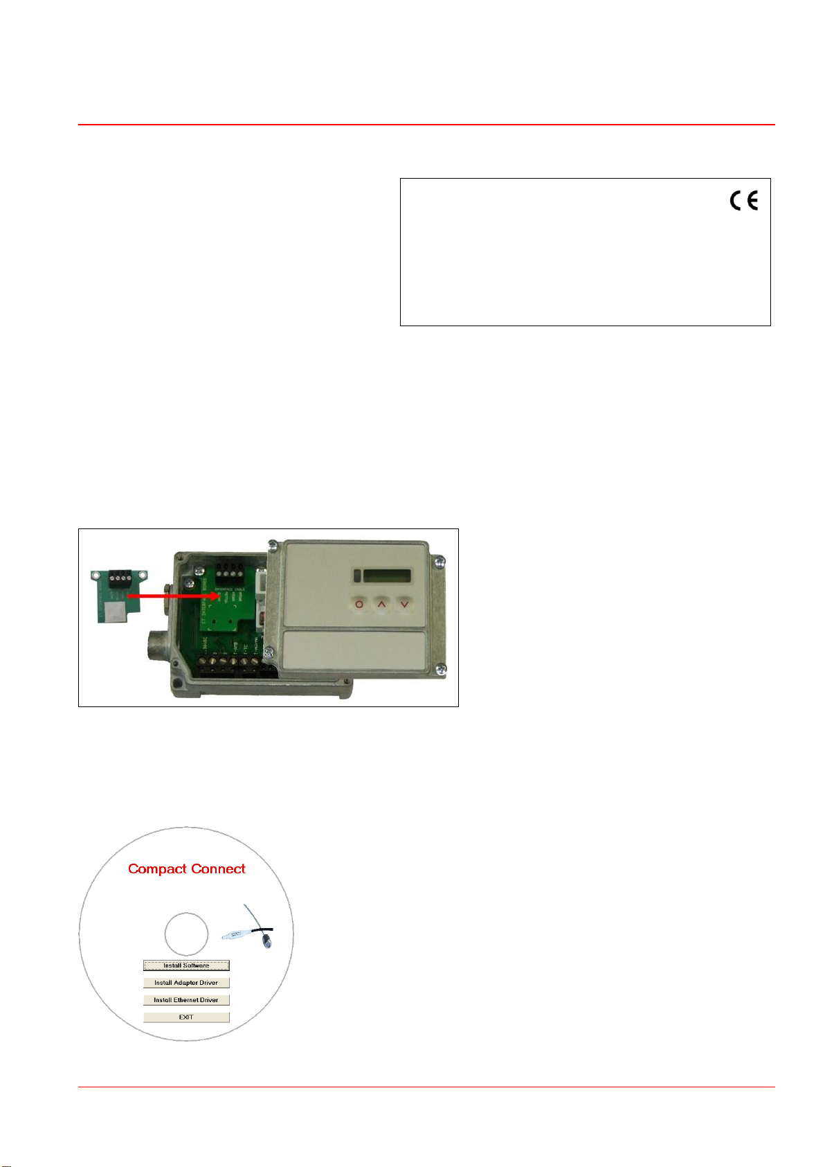
1. Hardware Installation
Please plug the Ethernet interface board into the place provided, which is located beside the display. In the
correct position the holes of the interface match with the thread holes of the CT box. Now press the PCB
downwards and fix it using both M3x5 screws. Exchange the blind screw on the CT box by the cable gland and
install the connection cable (interface board – Ethernet adapter). Make sure the wiring is correct according to the
wire colours printed on the interface board.
Please connect the shield of the cable with the electronics housing (inside the cable gland).
The CT unit needs a power supply for operation with at minimum 12 V.
Please connect the Ethernet adapter device with your network using an Ethernet cable.
2. Network Installation
Insert the installation CD into the according drive on your computer. If the autorun option is activated the
installation wizard will start automatically. Otherwise please start CDsetup.exe from the CD-ROM.
The following screen will appear. Please select Install Ethernet Driver.
ACCTETHNK-MAD-E2016-10-A
1/5
Page 2
Manual Addendum
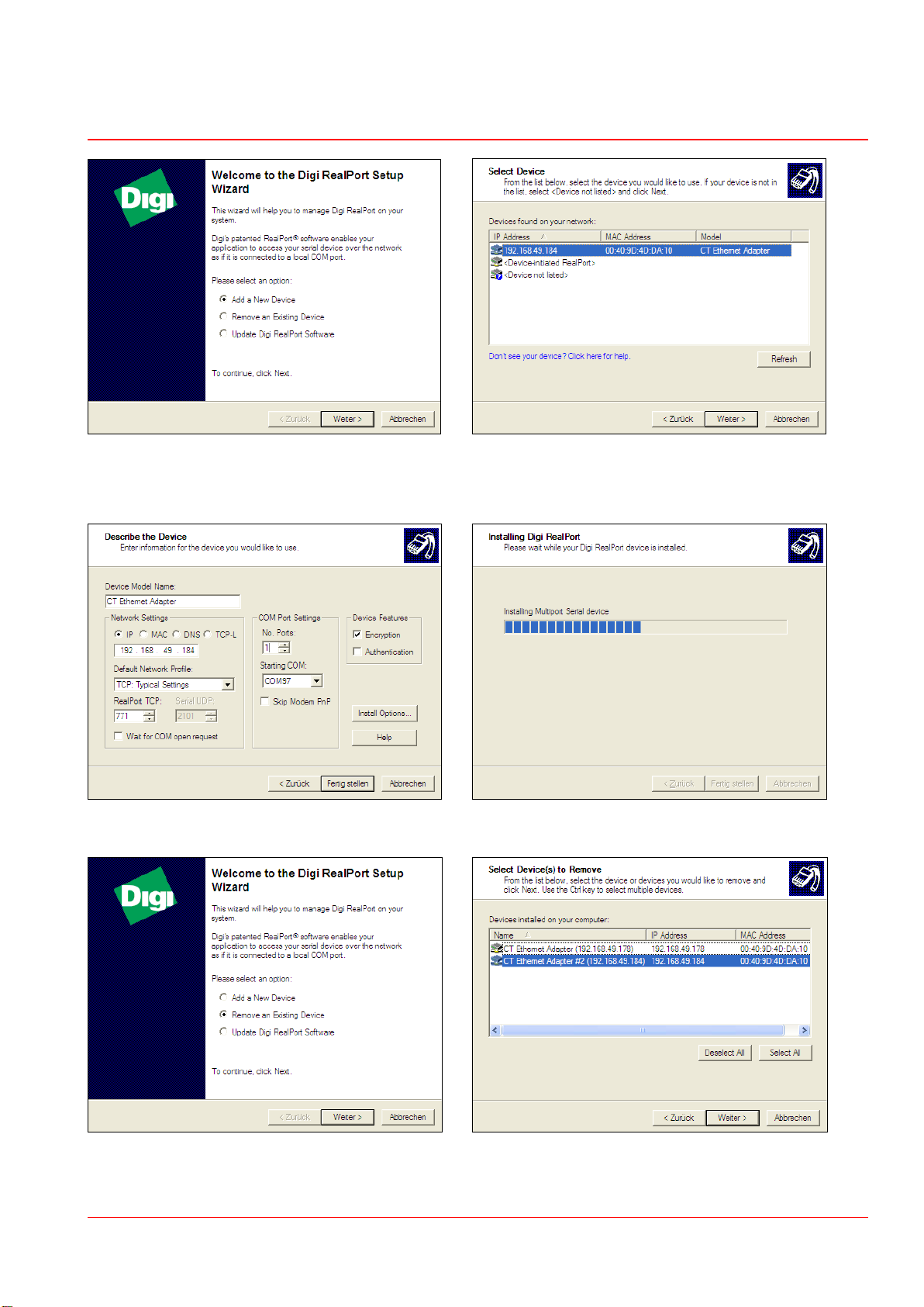
Select Add New Device and press Continue. The IP- and MAC-address of the Ethernet adapter will appear
in the list. You will find the MAC address also printed on the
Ethernet adapter. Please mark the adapter in the list and press
Continue.
The following screen shows all settings. Please press The device will be installed inside the network.
Finish.
To deinstall an adapter please follow the steps described In the following overview all on the PC installed Ethernet
under Network Installation. Select Remove an Existing adapter are shown. Select the adapter(s) which should be
Device and then Continue. deinstalled and press Continue.
ACCTETHNK-MAD-E2016-10-A
2/5
Page 3

Manual Addendum
3. Direct Connection to a PC
If a direct connection between Ethernet adapter and PC is required the adapter and the PC need to get a fixed IP
address. After the network installation please open the Windows device manager (Start/ Control panel/ System/
Hardware/ Device manager).
Please choose Multi adapter (serial) from the list. Please open the tab Advanced in this window.
By double click on the desired Ethernet adapter Beside Device UI you will find a link with the network IP
a properties window is opening. address.
By clicking on the link the configuration page for the Ethernet adapter will be opened in your web browser.
The PC must be connected to the internet for this purpose.
Please select Network (Navigation left; below Configuration).
ACCTETHNK-MAD-E2016-10-A
3/5
Page 4

Manual Addendum
In the input mask below Use the following IP address you can now enter a fixed IP address.
Confirm your settings with Apply.
For a communication with the adapter you now have to configure the network settings on your PC.
Please open the LAN settings (Start/ Control panel/ Network settings/ Settings):
Mark the LAN connection and open the properties window (right mouse button)
Double click on Internet protocol (TCP/ IP) Please enter a fixed IP address here for the PC.
Please note that the first three blocks have to match with the IP address
of the adapter device (example: 192.168.049).
Press OK. The installation is finished.
ACCTETHNK-MAD-E2016-10-A
4/5
Page 5

Manual Addendum
4. Settings inside the CompactConnect software
After a successful network installation of the Ethernet adapter you can start the CompactConnect software.
To make sure that an available device can be found you should activate at first the function Scan non-USB
devices in the menu point Preferences/ Options:
Further you should set the Communication mode to Standard (Menu: Measurement/ Settings).
This activates the so called polling mode (bi-directional communication).
4. Reset of the Adapter
The Ethernet adapter can be reset to the factory default configuration. Please use a ballpen to reach the reset
button (hole on top of the housing):
Power on the device while holding the Reset button down.
After a few seconds you may see a blink of the green LED (network connection).
Wait until you see the green LED blink a 1-5-1 pattern 1), then release the reset button.
Wait for the device to boot up. At this time, the configuration is returned to factory defaults.
Powering off the device before releasing the button guarantees the configuration will NOT be reverted.
Powering off the device just after releasing the button will result in an unknown configuration, possibly having some or
1)
blink – pause – 5xblink – pause – blink
all settings reverted to defaults.
After the reset the adapter works in the DHCP mode. If you like to establish a direct connection to a PC
please follow this instruction, chapter 3.
ACCTETHNK-MAD-E2016-10-A
5/5
 Loading...