

Page 1
optris
®
CSvideo
Infrared-thermometer
2M
Operator’s Manual
Page 2

Optris GmbH
Ferdinand-Buisson-Str. 14
13127 Berlin
Germany
Tel.: +49 30 500 197-0
Fax: +49 30 500 197-10
E-mail: info@optris.de
Internet: www.optris.de
Page 3

-Table of Contents 3-
Table of Contents
Table of Contents ............................................................................................................................................. 3
1 General Information ................................................................................................................................. 6
1.1 Description ....................................................................................................................................... 6
1.2 Warranty ........................................................................................................................................... 7
1.3 Scope of Supply ............................................................................................................................... 7
1.4 Maintenance ..................................................................................................................................... 8
1.5 Model Overview ................................................................................................................................ 8
1.6 Factory Default Settings ................................................................................................................... 9
2 Technical Data ........................................................................................................................................ 11
2.1 General Specifications ................................................................................................................... 11
2.2 Electrical Specifications .................................................................................................................. 12
2.3 Measurement Specifications .......................................................................................................... 13
Page 4

-4 -
2.4 Optics ............................................................................................................................................. 14
3 Mechanical Installation .......................................................................................................................... 16
4 Accessories ............................................................................................................................................ 17
4.1 Mounting Brackets .......................................................................................................................... 17
4.2 Air Purge Collar .............................................................................................................................. 18
4.3 Water Cooled Housing ................................................................................................................... 19
5 Electrical Installation ............................................................................................................................. 20
5.1 Cable Connections ......................................................................................................................... 20
5.2 Power supply .................................................................................................................................. 20
5.3 Analog Mode .................................................................................................................................. 22
5.4 Digital Mode ................................................................................................................................... 23
5.5 Maximum Loop Impedance ............................................................................................................ 24
6 Sighting ................................................................................................................................................... 25
6.1 Focusing and Video Sighting ......................................................................................................... 26
Page 5

-Table of Contents 5-
7 Software CompactConnect ................................................................................................................... 27
7.1 Installation ...................................................................................................................................... 27
7.2 Communication Settings ................................................................................................................ 28
7.3 Digital Command Set ..................................................................................................................... 29
8 Basics of Infrared Thermometry........................................................................................................... 30
9 Emissivity ............................................................................................................................................... 31
9.1 Definition......................................................................................................................................... 31
9.2 Determination of unknown Emissivities .......................................................................................... 31
9.3 Characteristic Emissivities.............................................................................................................. 32
Appendix A – Emissivity Table Metals ......................................................................................................... 33
Appendix B – Emissivity Table Non Metals ................................................................................................. 35
Appendix C – Smart Averaging ..................................................................................................................... 36
Appendix D – Declaration of Conformity ..................................................................................................... 37
Page 6
-6 -
The CSvideo sensing head is a sensitive optical system. Please use only the thread for
mechanical installation.
Avoid abrupt changes of the ambient temperature.
Avoid mechanical violence on the head – this may destroy the system (expiry of warranty).
If you have any problems or questions, please contact our service department.
Read the manual carefully before the initial start-up. The producer reserves the right to change
the herein described specifications in case of technical advance of the product.
1 General Information
1.1 Description
Thank you for choosing the optris® CSvideo infrared thermometer.
The sensors of the optris CSvideo series are noncontact infrared temperature sensors.
They calculate the surface temperature based on the emitted infrared energy of objects [►8 Basics of
Infrared Thermometry]. The alignment of the sensor can be done with the integrated video sighting and
cross laser aiming.
The sensor housing of the CSvideo head is made of stainless steel (IP65/ NEMA-4 rating).
Page 7

-General Information 7-
► All accessories can be ordered according to the referred part numbers in brackets [ ].
1.2 Warranty
Each single product passes through a quality process. Nevertheless, if failures occur please contact the
customer service at once. The warranty period covers 24 months starting on the delivery date. After the
warranty is expired the manufacturer guarantees additional 6 months warranty for all repaired or substituted
product components. Warranty does not apply to damages, which result from misuse or neglect. The
warranty also expires if you open the product. The manufacturer is not liable for consequential damage or in
case of a non-intended use of the product.
If a failure occurs during the warranty period the product will be replaced, calibrated or repaired without
further charges. The freight costs will be paid by the sender. The manufacturer reserves the right to
exchange components of the product instead of repairing it. If the failure results from misuse or neglect the
user has to pay for the repair. In that case you may ask for a cost estimate beforehand.
1.3 Scope of Supply
CSvideo
Mounting nut and mounting bracket (fixed)
5 m USB cable
Software CompactConnect
Operators manual
Page 8
-8 -
Never use cleaning compounds which contain solvents (neither for the lens nor for the housing).
Model
Model code
Measurement range
Spectral
response
Typical applications
CSvideo 2M
2ML
250 to 800 °C
1,6 µm
Metals and ceramic surfaces
2MH
385 to 1600 °C
1.4 Maintenance
Lens cleaning: Blow off loose particles using clean compressed air. The lens surface can be cleaned with a
soft, humid tissue moistened with water or a water based glass cleaner.
1.5 Model Overview
The sensors of the CSvideo series are available in the following basic versions:
In the following chapters of this manual you will find only the short model codes.
Page 9

-General Information 9-
Signal output object temperature
4-20 mA
Emissivity
1,000
Transmissivity
1,000
Average time (AVG)
0,1 s
Smart Averaging
active
Peak hold
inactive
Valley hold
Inactive
2ML
2MH
Lower limit temperature range [°C]
250
385
Upper limit temperature range [°C]
800
1600
Lower limit signal output
4 mA
Upper limit signal output
20 mA
Temperature unit
°C
Ambient temperature compensation
internal head temperature probe
Laser
active
1.6 Factory Default Settings
The unit has the following presetting at time of delivery:
Page 10

-10 -
Smart Averaging means a dynamic average adaptation at high signal edges.
[Activation via software only].
►Appendix C – Smart Averaging
Page 11

-Technical Data 11-
Environmental rating
IP65 (NEMA-4)
Ambient temperature 1)
-20…70 °C
Storage temperature
-40...85 °C
Relative humidity
10...95 %, non condensing
Material
stainless steel
Dimensions
118,5 mm x 50 mm, M48x1,5
Weight
600 g
Cable length (analog+alarm)
3 m, 8 m, 15 m
Cable length (USB)
5 m (incl.), 10 m, 20 m
Cable diameter
5 mm
Ambient temperature cable
80 °C max. [High temperature cable (optional): 180 °C]
Vibration
IEC 68-2-6: 3G, 11 – 200 Hz, any axis
Shock
IEC 68-2-27: 50G, 11 ms, any axis
Software (optional)
CompactConnect
2 Technical Data
2.1 General Specifications
1)
The lasers will turn off automatically at ambient temperatures >50 °C.
Page 12

-12 -
Power Supply
5–30 VDC
Current draw (laser)
45 mA @ 5 V
20 mA @ 12 V
12 mA @ 24 V
Aiming laser
Crosshair laser, 635 nm, 1 mW, On/ Off via external switch (needs to be installed by user before
start-up) or software
Video sighting
Digital (USB 2.0), 640 x 480 px, FOV 3.1° x 2.4°
Output/ analog
4–20 mA current loop
Alarm output
Programmable open collector output at RxD pin [0-30 V/ 500 mA]
Output impedance
max. loop resistance 1000 Ω (in dependence on supply voltage)
Output/ digital
USB 2.0
2.2 Electrical Specifications
Page 13

-Technical Data 13-
2ML
2MH
Temperature range (scalable)
250...800 °C
385...1600 °C
Spectral range
1,6 µm
Optical resolution
150:1
300:1
System accuracy
1), 2)
±(0,3 % of reading +2 °C)
Repeatability
1), 2)
±(0,1 % of reading +1 °C)
Temperature resolution
0,1 K
Response time (90% signal)
10 ms
Emissivity/ Gain
0,100…1,100 (adjustable via switches on sensor or via software)
IR window correction
0,100…1,000 (adjustable via software)
Signal processing
Average, peak hold, valley hold, extended hold functions with threshold
and hysteresis (adjustable via software)
2.3 Measurement Specifications
1)
at ambient temperature 235 °C
2)
= 1/ Response time 1 s
Page 14

-14 -
Optics
Focus adjustable in the range
SFV
200 mm till infinity
CFV
90 mm till 250 mm
The size of the measuring object and the optical resolution of the infrared thermometer
determine the maximum distance between sensing head and measuring object.
In order to prevent measuring errors the object should fill out the field of view of the optics
completely.
Consequently, the spot should at all times have at least the same size like the object or should
be smaller than that.
2.4 Optics
The vario optics of the CSvideo allows a smooth focusing of the optics to the desired distance. The sensors
are available in two optic versions:
The following tables show the diameter of the measuring spot for some selected distances. The spot size
refers to 90 % of the radiation energy.
The distance is always measured from the front edge of the sensing head.
As an alternative to the optical diagrams, the spot size calculator can also be used on the optris website
http://www.optris.com/spot-size-calculator.
Page 15

-Technical Data 15-
spot size mm 1,3 2,0 3,0 4,7 7,3 10,7 16,7 33,3
measurement distance mm 200 300 450 700 1100 1600 2500 5000
2ML: SF optics (D:S=150:1)
spot size mm 0,6 0,8 1,0 1,2 1,4 1,7
measurement distance mm 90 120 150 180 210 250
2ML: CF optics (D:S=150:1)
spot size mm 0,7 1,0 1,5 2,3 3,7 5,3 8,3 16,7
measurement distance mm 200 300 450 700 1100 1600 2500 5000
2MH: SF optics (D:S=300:1)
spot size mm 0,3 0,4 0,5 0,6 0,7 0,8
measurement distance mm 90 120 150 180 210 250
2MH: CF optics (D:S=300:1)
Page 16

-16 -
Make sure to keep the optical path clear of any obstacles.
3 Mechanical Installation
The CSvideo is equipped with a metric M48x1,5 thread and can be installed either directly via the sensor
thread or with help of the supplied mounting nut (standard) and fixed mounting bracket (standard) to a
mounting device available.
CSvideo sensing head
Page 17

-Accessories 17-
For an exact sensor alignment to the object
please activate the integrated video and/ or cross
laser sighting.
[►6 Sighting]
4 Accessories
4.1 Mounting Brackets
Mounting bracket, adjustable in one axis [ACCTLFB]
Mounting bracket, adjustable in two axes [ACCTLAB]
Page 18

-18 -
The needed amount of air (approx. 2...10 l/ min.)
depends on the application and the installation
conditions on-site.
4.2 Air Purge Collar
The lens must be kept clean at all times from dust, smoke, fumes and other contaminants in order to avoid
reading errors. These effects can be reduced by using an air purge collar. Make sure to use oil-free,
technically clean air, only.
Air purge collar [ACCTLAP]
Hose connection: 6x8 mm
Thread (fitting): G 1/8 inch
Page 19
-Accessories 19-
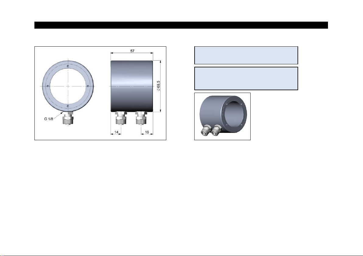
To avoid condensation on the optics
an air purge collar is recommended.
Water flow rate: approx. 2 l/ min
(Cooling water temperature should not
exceed 30 °C)
4.3 Water Cooled Housing
Water cooled housing [ACCTLW]
Hose connection: 6x8 mm
Thread (fitting): G 1/8 inch
The CSvideo can be used at ambient temperatures up to 70 °C without cooling. For applications, where the
ambient temperature can reach higher values, the usage of the optional water cooled housing is
recommended (operating temperature up to 175 °C). The sensor should be equipped with the optional high
temperature cables (operating temperature up to 180 °C).
Page 20

-20 -
5 Electrical Installation
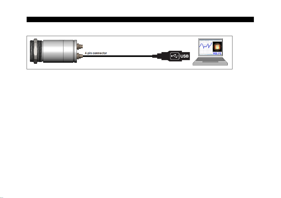
5.1 Cable Connections
The CSvideo has two connector plugs integrated in the sensor backplane.
Therefore an opening of the sensor for cable assembling is not necessary.
For connection to a PC you can use the supplied 5 m USB cable with a
4-pin sensor connector (lengths of 10 m and 20 m are optional available).
For the analog connection (4-20 mA current loop, alarm, laser) a cable with
a 7-pin plug is needed. This cable is not included in the scope of
supply and has to be ordered separately.
Lengths of 3, 8 and 15 m are available.
Please use the original ready-made, fitting connection cables.
5.2 Power supply
Please use a separate, stabilized power supply unit with an output voltage of 5–30 VDC which can supply
100 mA. The ripple should be max. 200 mV.
Please use shielded cables only for all power and data lines.
The sensor shield has to be grounded.
Page 21

-Electrical Installation 21-
Pin assignment of 7-pin connector (current loop/ alarm/ laser)
PIN designation wire color (original sensor cable)
1 – yellow
2 LOOP – brown
3 LOOP + white
4 Alarm green
5 LASER – grey
6 LASER + pink
7 –
Connector plug (Outer view)
Pin assignment of 4-pin connector (USB)
PIN designation
1 VCC
2 GND
3 D4 D+
Page 22

-22 -
5.3 Analog Mode
If the CSvideo is used as analog device the sensor provides beside the 4-20 mA signal in addition an alarm
output (open-collector). To activate the alarm output and set the alarm threshold value the software is
needed.
The supply line for the sighting laser must be led via a switch or pushbutton, which has to be
installed max. 2 m away from installation site of the sensor.
With a laptop or tablet PC, the sensor parameterization and alignment can be carried out on site. The USB
cable can be plugged into the sensor during operation (hot plug & play).
Page 23
-Electrical Installation 23-
5.4 Digital Mode
In the digital mode the sensor and the laser will be powered via the 5 V from USB interface. The activation/
deactivation of the laser has to be made via the software.
The sensor is offering two ways of digital communication:
bidirectional communication (sending and receiving data)
unidirectional communication (burst mode – the sensor is sending data only)
Page 24

-24 -
5.5 Maximum Loop Impedance
The maximum impedance of the current loop depends on the supply voltage level:
Page 25

-Sighting 25-
WARNING: Do not point the laser directly
at the eyes of persons or animals!
Do not stare into the laser beam. Avoid
indirect exposure via reflective surfaces!
The laser should only be used for sighting and positioning of the sensor. A permanent use of the laser can
reduce the lifetime of the laser diodes and also the measurement accuracy can be affected.
6 Sighting
The CSvideo has an integrated video camera which is using the same optical channel than the IR detector.
In addition the sensor has a cross laser aiming which marks the center of the measurement spot at any
distance. The combination of video and laser sighting enables a perfect alignment of the sensor to the
object.
The supply line for the sighting laser must be led via a switch or pushbutton, which has to be
installed max. 2 m away from installation site of the sensor.
The laser can be activated/ deactivated via this switch (which needs to be installed by the user) or via the
software.
At ambient temperatures >50 °C the laser will be switched off automatically.
Page 26

-26 -
6.1 Focusing and Video Sighting
On the back plane of the sensor you will find a rotary button for focusing of the
optics.
To set the focus to the desired measurement distance you have to connect
the sensor with a PC using the USB cable. Please start the CompactConnect
software. You will see the video beside the temperature-time diagram. The
position of the measurement spot is indicated by a circle inside the video
picture. The size of this circle is equivalent to the IR spot size.
By turning the rotary button clockwise you will change the focus in direction far. By turning
counterclockwise you will change the focus in direction close.
After a successful focusing please enter the measurement distance (distance sensor front – object) in the
according field in the software (underneath the video picture).
You will find a detailed description of the video
settings in the software description which you can
call via the menu [?/ Help...].
Page 27

-Software CompactConnect 27-
Min. system requirements:
Windows XP, Vista, 7, 8, 10
USB interface
Hard disc with at least 30 MByte free space
At least 128 MByte RAM
CD-ROM drive
You will find a detailed software manual on the CD.
7 Software CompactConnect
7.1 Installation
Insert the installation CD into the according drive on
your computer. If the autorun option is activated the
installation wizard will start automatically.
Otherwise please start CDsetup.exe from the CDROM. Follow the instructions of the wizard until the
installation is finished.
The installation wizard will place a launch icon on the desktop and in the start menu:
[Start]\Programs\CompactConnect.
If you want to uninstall the software from your system please use the uninstall icon in the start menu.
Main Features:
Alignment of the sensor
Graphic display for temperature trends and automatic data logging
and video snapshot generation for analysis and documentation
Complete sensor setup and remote controlling
Adjustment of signal processing functions
Programming of outputs and functional inputs
Page 28

-28 -
7.2 Communication Settings
Serial Interface
Baud rate: 9600 baud
Data bits: 8
Parity: none
Stop bits: 1
Flow control: off
Protocol
All sensors of the CSvideo series are using a binary protocol. To get a fast communication the protocol has
no additional overhead with CR, LR or ACK bytes.
To power the sensor the control signal ”DTR“ has to be reset.
Page 29

-Software CompactConnect 29-
7.3 Digital Command Set
Page 30

-30 -
8 Basics of Infrared Thermometry
Depending on the temperature each object emits a certain amount of infrared radiation. A change in the
temperature of the object is accompanied by a change in the intensity of the radiation. For the measurement
of “thermal radiation” infrared thermometry uses a wave-length ranging between 1 µm and 20 µm.
The intensity of the emitted radiation depends on the material. This material contingent constant is described
with the help of the emissivity which is a known value for most materials (►9 Emissivity).
Infrared thermometers are optoelectronic sensors. They calculate the surface temperature on the basis of
the emitted infrared radiation from an object. The most important feature of infrared thermometers is that
they enable the user to measure objects contactless. Consequently, these products help to measure the
temperature of inaccessible or moving objects without difficulties. Infrared thermometers basically consist of
the following components:
lens
spectral filter
detector
electronics (amplifier/ linearization/ signal processing)
The specifications of the lens decisively determine the optical path of the infrared thermometer, which is
characterized by the ratio Distance to Spot size.
The spectral filter selects the wavelength range, which is relevant for the temperature measurement. The
detector in cooperation with the processing electronics transforms the emitted infrared radiation into electrical
signals.
Page 31

-Emissivity 31-
9 Emissivity
9.1 Definition
The intensity of infrared radiation, which is emitted by each body, depends on the temperature as well as on
the radiation features of the surface material of the measuring object. The emissivity (ε – Epsilon) is used as
a material constant factor to describe the ability of the body to emit infrared energy. It can range between 0
and 100 %. A “blackbody” is the ideal radiation source with an emissivity of 1,0 whereas a mirror shows an
emissivity of 0,1.
If the emissivity chosen is too high, the infrared thermometer may display a temperature value which is much
lower than the real temperature – assuming the measuring object is warmer than its surroundings. A low
emissivity (reflective surfaces) carries the risk of inaccurate measuring results by interfering infrared radiation
emitted by background objects (flames, heating systems, chamottes). To minimize measuring errors in such
cases, the handling should be performed very carefully and the unit should be protected against reflecting
radiation sources.
9.2 Determination of unknown Emissivities
► First, determine the actual temperature of the measuring object with a thermocouple or contact sensor.
Second, measure the temperature with the infrared thermometer and modify the emissivity until the
displayed result corresponds to the actual temperature.
► If you monitor temperatures of up to 380 °C you may place a special plastic sticker (emissivity dots – part
number: ACLSED) onto the measuring object, which covers it completely. Now set the emissivity to 0,95
Page 32

-32 -
and take the temperature of the sticker. Afterwards, determine the temperature of the adjacent area on
the measuring object and adjust the emissivity according to the value of the temperature of the sticker.
► Cove a part of the surface of the measuring object with a black, flat paint with an emissivity of 0,98. Adjust
the emissivity of your infrared thermometer to 0,98 and take the temperature of the colored surface.
Afterwards, determine the temperature of a directly adjacent area and modify the emissivity until the
measured value corresponds to the temperature of the colored surface.
CAUTION: On all three methods the object temperature must be different from ambient temperature.
9.3 Characteristic Emissivities
In case none of the methods mentioned above help to determine the emissivity you may use the emissivity
tables ►Appendix A – Emissivity Table Metals and Appendix B – Emissivity Table Non Metals. These
are average values, only. The actual emissivity of a material depends on the following factors:
temperature
measuring angle
geometry of the surface
thickness of the material
constitution of the surface (polished, oxidized, rough, sandblast)
spectral range of the measurement
transmissivity (e.g. with thin films)
Page 33

-Appendix A – Emissivity Table Metals 33-
1,0 µm 1,6 µm 5,1 µm 8-14 µm
Aluminium non oxidized 0,1-0,2 0,02-0,2 0,02-0,2 0,02-0,1
polished 0,1-0,2 0,02-0,1 0,02-0,1 0,02-0,1
roughened 0,2-0,8 0,2-0,6 0,1-0,4 0,1-0,3
oxidized 0,4 0,4 0,2-0,4 0,2-0,4
Brass polished 0,35 0,01-0,05 0,01-0,05 0,01-0,05
roughened 0,65 0,4 0,3 0,3
oxidized 0,6 0,6 0,5 0,5
Copper polished 0,05 0,03 0,03 0,03
roughened 0,05-0,2 0,05-0,2 0,05-0,15 0,05-0,1
oxidized 0,2-0,8 0,2-0,9 0,5-0,8 0,4-0,8
Chrome 0,4 0,4 0,03-0,3 0,02-0,2
Gold 0,3 0,01-0,1 0,01-0,1 0,01-0,1
Haynes alloy 0,5-0,9 0,6-0,9 0,3-0,8 0,3-0,8
Inconel electro polished 0,2-0,5 0,25 0,15 0,15
sandblast 0,3-0,4 0,3-0,6 0,3-0,6 0,3-0,6
oxidized 0,4-0,9 0,6-0,9 0,6-0,9 0,7-0,95
Iron non oxidized 0,35 0,1-0,3 0,05-0,25 0,05-0,2
rusted 0,6-0,9 0,5-0,8 0,5-0,7
oxidized 0,7-0,9 0,5-0,9 0,6-0,9 0,5-0,9
forged, blunt 0,9 0,9 0,9 0,9
molten 0,35 0,4-0,6
Iron, casted non oxidized 0,35 0,3 0,25 0,2
oxidized 0,9 0,7-0,9 0,65-0,95 0,6-0,95
Material
typical Emissivity
Spectral response
Appendix A – Emissivity Table Metals
Page 34

-34 -
1,0 µm 1,6 µm 5,1 µm 8-14 µm
Lead polished 0,35 0,05-0,2 0,05-0,2 0,05-0,1
roughened 0,65 0,6 0,4 0,4
oxidized 0,3-0,7 0,2-0,7 0,2-0,6
Magnesium 0,3-0,8 0,05-0,3 0,03-0,15 0,02-0,1
Mercury 0,05-0,15 0,05-0,15 0,05-0,15
Molybdenum non oxidized 0,25-0,35 0,1-0,3 0,1-0,15 0,1
oxidized 0,5-0,9 0,4-0,9 0,3-0,7 0,2-0,6
Monel (Ni-Cu) 0,3 0,2-0,6 0,1-0,5 0,1-0,14
Nickel electrolytic 0,2-0,4 0,1-0,3 0,1-0,15 0,05-0,15
oxidized 0,8-0,9 0,4-0,7 0,3-0,6 0,2-0,5
Platinum black 0,95 0,9 0,9
Silver 0,04 0,02 0,02 0,02
Steel polished plate 0,35 0,25 0,1 0,1
rustless 0,35 0,2-0,9 0,15-0,8 0,1-0,8
heavy plate 0,5-0,7 0,4-0,6
cold-rolled 0,8-0,9 0,8-0,9 0,8-0,9 0,7-0,9
oxidized 0,8-0,9 0,8-0,9 0,7-0,9 0,7-0,9
Tin non oxidized 0,25 0,1-0,3 0,05 0,05
Titanium polished 0,5-0,75 0,3-0,5 0,1-0,3 0,05-0,2
oxidized 0,6-0,8 0,5-0,7 0,5-0,6
Wolfram polished 0,35-0,4 0,1-0,3 0,05-0,25 0,03-0,1
Zinc polished 0,5 0,05 0,03 0,02
oxidized 0,6 0,15 0,1 0,1
Spectral response
Material
typical Emissivity
Page 35

-Appendix B – Emissivity Table Non Metals 35-
1,0 µm 2,2 µm 5,1 µm 8-14 µm
Asbestos 0,9 0,8 0,9 0,95
Asphalt 0,95 0,95
Basalt 0,7 0,7
Carbon non oxidized 0,8-0,9 0,8-0,9 0,8-0,9
graphite 0,8-0,9 0,7-0,9 0,7-0,8
Carborundum 0,95 0,9 0,9
Ceramic 0,4 0,8-0,95 0,8-0,95 0,95
Concrete 0,65 0,9 0,9 0,95
Glass plate 0,2 0,98 0,85
melt 0,4-0,9 0,9
Grit 0,95 0,95
Gypsum 0,4-0,97 0,8-0,95
Ice 0,98
Limestone 0,4-0,98 0,98
Paint non alkaline 0,9-0,95
Paper any color 0,95 0,95
Plastic >50 µm non transparent 0,95 0,95
Rubber 0,9 0,95
Sand 0,9 0,9
Snow 0,9
Soil 0,9-0,98
Textiles 0,95 0,95
Water 0,93
Wood natural 0,9-0,95 0,9-0,95
Material
typical Emissivity
Spectral response
Appendix B – Emissivity Table Non Metals
Page 36
-36 -
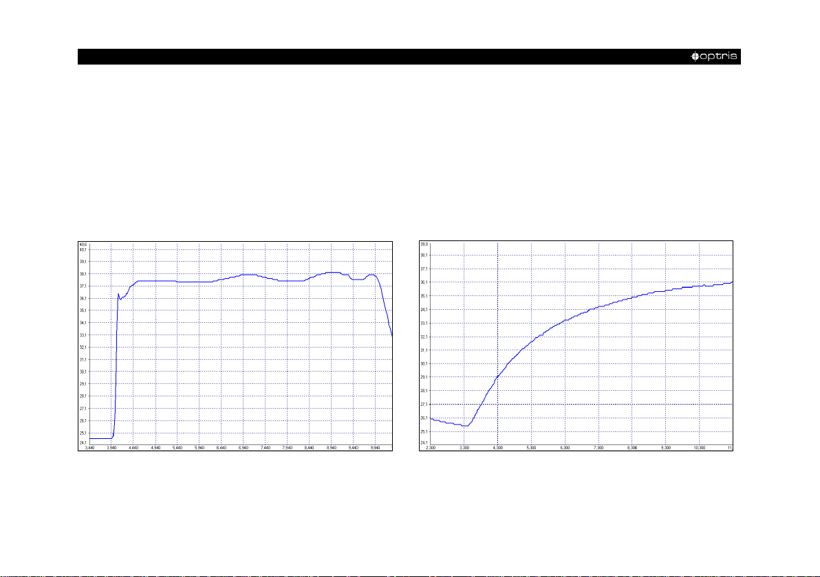
Appendix C – Smart Averaging
The average function is generally used to smoothen the output signal. With the adjustable parameter time
this function can be optimal adjusted to the respective application. One disadvantage of the average function
is that fast temperature peaks which are caused by dynamic events are subjected to the same averaging
time. Therefore those peaks can only be seen with a delay on the signal output.
The function Smart Averaging eliminates this disadvantage by passing those fast events without averaging
directly through to the signal output.
Signal graph with Smart Averaging function Signal graph without Smart Averaging function
Page 37
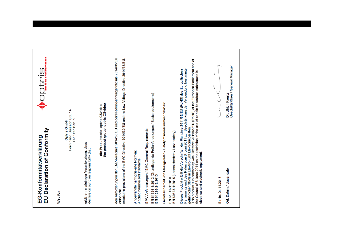
-Appendix D – Declaration of Conformity 37-
Appendix D – Declaration of Conformity
Page 38

optris CSvideo-MA-E2017-08-A
 Loading...