

Page 1

optris® CS/ CSmicro
¯¯¯¯¯¯¯¯¯¯¯¯¯¯¯¯¯¯¯¯¯¯¯¯¯¯¯¯¯¯¯¯¯¯¯¯¯¯¯¯¯¯¯¯¯¯¯¯¯¯¯¯¯¯¯¯¯¯¯¯¯¯¯¯¯¯¯¯¯¯¯¯¯¯¯¯¯¯¯¯¯¯¯¯¯¯¯¯¯¯¯¯¯¯¯¯¯¯¯¯¯¯¯¯¯¯¯¯¯¯¯¯¯¯¯¯¯¯¯¯¯¯¯¯¯¯¯¯¯¯¯¯¯¯¯¯¯¯¯¯¯¯¯¯¯¯¯¯¯¯¯¯¯¯¯¯¯¯¯¯¯¯¯¯¯¯¯¯¯¯¯¯¯¯¯¯¯¯¯¯¯¯¯¯¯¯¯¯¯¯¯¯¯¯¯¯¯¯¯¯¯¯¯¯¯¯¯¯¯¯¯¯¯¯¯¯¯¯¯¯
Infrared Sensor
Operators manual
Page 2

Page 3
optris CS/ CSmicro – E2007-03-A
1
CE-Conformity
Optris GmbH
Str. 49, Nr. 14
D – 13127 Berlin
GERMANY
Tel.: +49-30-500 197-0
Fax: +49-30-500 197-10
E-mail: info@optris.de
Internet: www.optris.com
The product complies with the following standards:
EMC: EN 61326-1
Safety Regulations: EN 61010-1:1993/ A2:1995
The product accomplishes the requirements of the EMC Directive
89/336/EEC and of the low-voltage directive 73/23/EEC.
Warranty
Each single product passes through a quality process. Nevertheless, if failures occur please contact the customer service at
once. The warranty period covers 24 months starting on the delivery date. After the warranty is expired the manufacturer
guarantees additional 6 months warranty for all repaired or substituted product components. Warranty does not apply to
damages, which result from misuse or neglect. The warranty also expires if you open the product. The manufacturer is not
liable for consequential damage. If a failure occurs during the warranty period the product will be replaced, calibrated or
repaired without further charges. The freight costs will be paid by the sender. The manufacturer reserves the right to
exchange components of the product instead of repairing it. If the failure results from misuse or neglect the user has to pay
for the repair. In that case you may ask for a cost estimate beforehand.
Page 4

optris CS/ CSmicro – E2007-03-A
2
Content
Page Page
Description 3 Device Information 31
Scope of Supply 3 Emissivity Calculation 31
Maintenance 3 Power Supply via Computer 32
Cautions 4 Command List 33
Factory Default Settings 4 Principle of Operation 34
Technical Data 5 Emissivity 35
General Specifications 5 Appendix A – Emissivity Table Metals 37
Electrical Specifications 6 Appendix B – Emissivity Table Non Metals 38
Measurement Specifications 7
Optical Charts 8
Close Focus Optics 9
Installation 10
Mechanical Installation 10
Mounting Accessories 11
Air Purge Collars 12
Further Accessories 13
Electrical Installation 14
Software CompactConnect 17
Installation 17
Connection to the Computer 18
Digital Displays 19
Diagram Functions 20
Device Setup 25
Page 5

optris CS/ CSmicro – E2007-03-A
3
Description
The sensors of the optris CS and CSmicro series are noncontact infrared temperature sensors.
They calculate the surface temperature based on the emitted infrared energy of objects [► Principle of
Operation].
The sensor housing of the optris CS is made of stainless steel (IP65/ NEMA-4 rating) and contains the complete
sensor electronics. The sensing head of the optris CSmicro is also made of stainless steel (IP65/ NEMA-4
rating) – the sensor electronics is part of the connection cable in that case.
Both of the sensors have a fixed mounted connection cable.
The sensors CS/ CSmicro are sensitive optical systems. Please use only the thread for mechanical
installation.
Avoid mechanical violence on the head – this may destroy the system (expiry of warranty).
Scope of Supply
CS/ CSmicro incl. connection cable, mounting nut and operators manual
USB interface cable with software (optional)
Maintenance
Lens cleaning: Blow off loose particles using clean
compressed air. The lens surface can be cleaned with a soft,
humid tissue moistened with water or a water based glass
cleaner.
PLEASE NOTE: Never use cleaning
compounds which contain solvents
(neither for the lens nor for the housing).
Page 6

optris CS/ CSmicro – E2007-03-A
4
Cautions
Avoid static electricity, arc welders, and induction heaters. Keep away from very strong EMF (electromagnetic
fields). Avoid abrupt changes of the ambient temperature.
In case of problems or questions which may arise when you use the CS/ CSmicro, please contact our service
department. The customer service staff will support you with questions concerning the optimization of the work
with the infrared thermometer, calibration procedures or with repairs.
Factory Default Settings
The unit has the following presetting at time of delivery:
Temperature range: 0…350°C
Output voltage: 0…3,5V
Emissivity: 0,950
Transmission: 1,000
Average time: 0,09s
Smart averaging: active
Ambient temperature source: Head temperature
If the unit is supplied together with the USB-kit (optional) the output will be set to digital communication
(bidirectional).
Read the manual carefully before the initial start-up. The producer reserves the right to change the herein
described specifications in case of technical advance of the product.
Page 7

optris CS/ CSmicro – E2007-03-A
5
Technical Data
General Specifications
CS CSmicro
Environmental rating IP65 (NEMA-4) IP65 (NEMA-4)
Ambient temperature -20…75°C -20…120°C (sensing head)
-20…70°C (electronic in cable)
Storage temperature -40…85°C -40…85°C
Relative humidity 10…95%, non condensing 10…95%, non condensing
Material stainless steel stainless steel
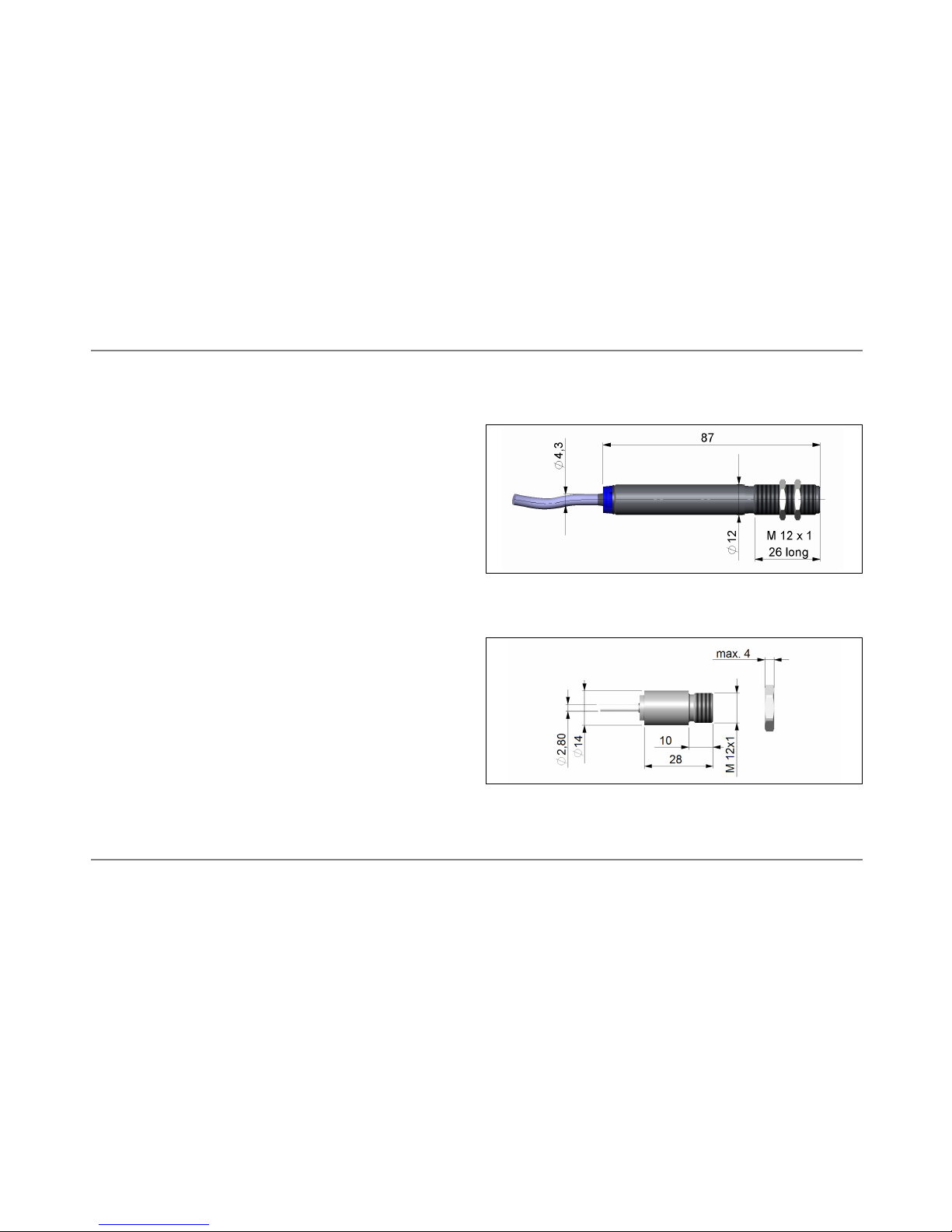
Dimensions M12x1, 85mm long 28mm x 14mm (head)/
70mm x 12mm (electronic)
Weight 58g 42g
Cable length 1m (standard), 3m, 8m, 15m 1m (50cm between head and
electronic)
Cable diameter 4,3mm 2,8mm (head-electronic)/
4,3mm (electronic-end of cable)
Vibration IEC 68-2-6: 3G, 11 – 200Hz, any axis IEC 68-2-6: 3G, 11 – 200Hz, any axis
Shock IEC 68-2-27: 50G, 11ms, any axis IEC 68-2-27: 50G, 11ms, any axis
EMI 89/336/EWG 89/336/EWG
Page 8
Electrical Specifications
CS CSmicro
Output [used pin] a only alternatively selectable e
Analog [OUT] 0-5V1) or 0-10V2)/ scalable 0-5V1) or 0-10V2)/ scalable
Serial digital
3)
[OUT+IN] uni- (burst mode) or bidirectional uni- (burst mode) or bidirectional
Alarm [OUT] output voltage adjustable; N/O or N/C output voltage adjustable; N/O or N/C
Additional features LED alarm indication/ Programmable open collector output
LED aiming support 24V DC/ 50mA [IN pin]
Output impedances min. 10kΩ load impedance min. 10kΩ load impedance
Input programmable functional input on green IN pin for:
external emissivity adjustment [0V ► ε=0,1 │ 5V ► ε=1,1]
ambient temperature compensation [0V ► -20°C │ 5V ► 350°C]
trigger (reset of hold functions) [5V at IN pin resets the selected hold function]
Current draw 9mA (12…28V DC)/ 15mA (5V DC) 9mA
Power supply 5…7V DC or 12…28V DC 5…28V DC
1)
0…4,6V at supply voltage 5V DC
2)
only at supply voltage ≥ 11V
3)
inverted RS232, TTL, 9,6 kBaud
white PS Power supply
optris CS/ CSmicro – E2007-03-A
6
yellow OUT Analog output/ TxD (5V)/ Alarm output
green IN Analog input/ RxD (5V)/ Open collector output (CSmicro only)
brown GND Ground (⊥)
black Shield
Page 9

optris CS/ CSmicro – E2007-03-A
7
Measurement Specifications
Temperature range IR: -20…350°C (scalable via software)
Spectral range: 8…14µm
Optical resolution: 10:1
CF-lens (optional): 1,2mm@ 10mm
Accuracy1): ±1,5°C or ±1,5% of reading
Repeatability
1)
: ±0,75°C or ±0,75% of reading
Temperature resolution
2)
: 0,2°C (NETD)
Response time: 30ms…2s (95% signal/ adjustable via software)
Warm-up time: 10min
Emissivity/ Gain: 0,100…1,100 (adjustable via 0-5V DC input or software)
Transmissivity: 0,100…1,000 (adjustable via software)
Interface (optional): USB programming interface
Signal processing: Average, Peak hold, Valley hold (adjustable via software)
Software (optional): CompactConnect
1)
at ambient temperature 23±5°C; whichever is greater
2)
NETD at object temperatures >20°C and time constant >0,2s
Page 10
optris CS/ CSmicro – E2007-03-A
8
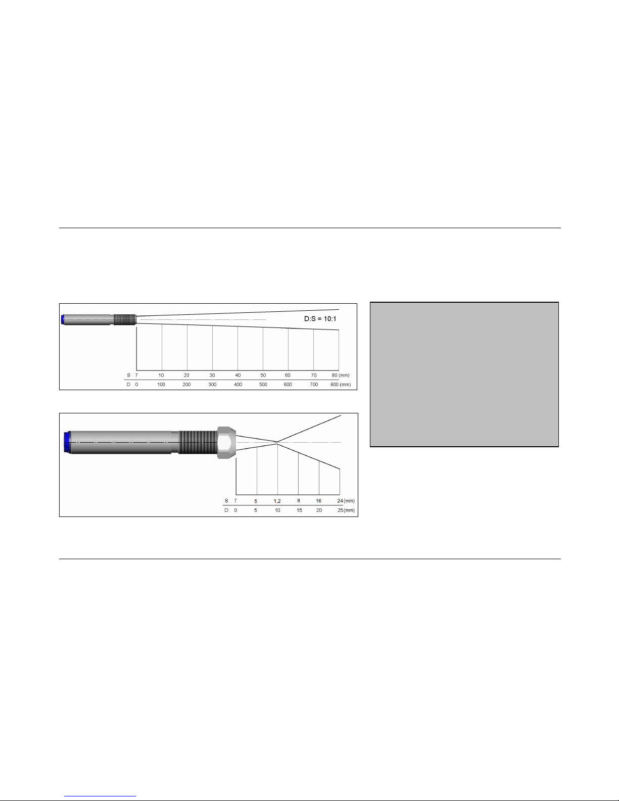
Optical Charts
The following optical charts show the diameter of the measuring spot in dependence on the distance between
measuring object and sensing head. The spot size refers to 90 % of the radiation energy.
The distance is always measured from the front edge of the sensor housing/ CF-lens holder/ air purge.
The size of the measuring object and
the optical resolution of the infrared
thermometer determine the maximum
distance between sensing head and
measuring object.
In order to prevent measuring errors the
object should fill out the field of view of
the optics completely.
Consequently, the spot should at all
times have at least the same size like
the object or should be smaller than
that.
Optical chart CS/ CSmicro (10:1)
Optical chart CS/ CSmicro with CF-lens (1,2mm@ 10mm)
Page 11
optris CS/ CSmicro – E2007-03-A
9
Close Focus Optics
The optional CF-lens allows the measurement of small objects. The CF optics can also be combined with a
laminar air purge:
CF-lens [ACCTCF] Laminar air purge with integrated CF-lens
[ACCTAPLCF]
If the CF-lens is used, the transmission has to be set to 0,78.
To change this value the optional USB-Kit (including CompactConnect software) is necessary.
Page 12
optris CS/ CSmicro – E2007-03-A
10
Installation
Mechanical Installation
The CS is equipped with a metric M12x1 thread and
can be installed either directly via the sensor thread or
with the help of the both hex nuts (standard) to the
mounting bracket available.
The LED aiming support helps to adjust the unit to
an object which has a temperature different to the
background. For this reason it might be necessary
to adjust the alarm value with the CompactConnect
software. With the factory default setting (alarm value: 100°C) the LED (ring at the junction sensor
housing – cable) will give blue light when the unit aims at a target with a temperature >100°C.
The CSmicro is also equipped with a metric M12x1
thread and can be installed either directly via the
sensor thread or with the help of the hex nut (standard)
to the mounting bracket available.
Various mounting accessories, fitting both CS and
CSmicro, can be ordered additionally.
Page 13

optris CS/ CSmicro – E2007-03-A
11
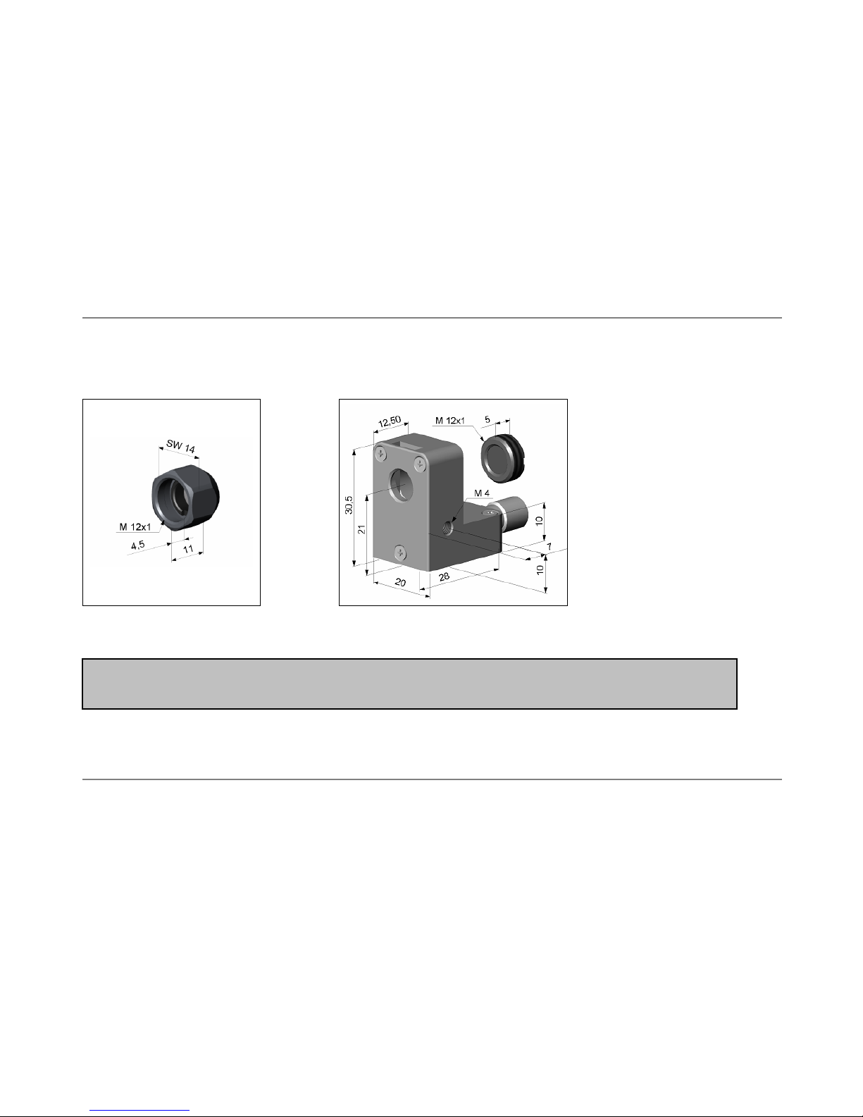
Mounting Accessories
Mounting bracket, adjustable in Mounting bolt with M12x1 thread, Mounting fork with M12x1
one axis [ACCTFB] adjustable in one axis [ACCTMB] thread, adjustable in 2 axes
[ACCTMG]
The Mounting fork can
be combined with the
Mounting bracket
[ACCTFB] using the
M12x1 thread.
Mounting bracket, adjustable in
two axes [ACCTAB]
Page 14

optris CS/ CSmicro – E2007-03-A
12
Air Purge Collars
The lens must be kept clean at all times from dust, smoke, fumes and other contaminants in order to avoid
reading errors. These effects can be reduced by using an air purge collar. Make sure to use oil-free, technically
clean air, only.
A
combination of the
Laminar air purge collar
with the bottom section
of the Mounting fork
allows an adjustment in
two axes.
[ACCTAPL+ACCTMG]
Standard air purge collar; Laminar air purge collar – the side air outlet
fits to the mounting bracket; prevents a cooling down of the object
hose connection: 3x5 mm in short distances; hose connection: 3x5 mm
[ACCSAP] [ACCTAPL]
The needed amount of air (approx. 2...10 l/ min.) depends on the
application and the installation conditions on-site.
Page 15

optris CS/ CSmicro – E2007-03-A
13
Further Accessories
Right angle mirror Protective window USB-Kit: USB programming adaptor
Enables measurement same mechanical size incl. terminal block and software CD
with 90° angle as CF lens [ACCSUSBK]
[ACCTRAM] [ACCTPW]
If the protective window is used, the transmission has to be set to 0,83.
To change this value the optional USB-Kit (including CompactConnect software) is necessary.
► All accessories can be ordered using the according part numbers in brackets [ ].
Page 16

Electrical Installation
Analog device (mV output on OUT pin)
optris CS/ CSmicro – E2007-03-A
14
Wire colors
Power white
OUT yellow
IN green
GND brown
Shield black
The output impedance must be ≥ 10kΩ.
Digital communication
For a digital communication the optional USB programming kit is
required. Please connect each wire of the USB adapter cable with the
same coloured wire of the sensor cable by using the terminal block.
Press with a screw driver as shown in the picture to loose a contact.
Page 17

The sensor is offering two ways of digital communication:
bidirectional communication (sending and receiving data)
unidirectional communication (burst mode – the sensor is only sending data)
Open collector output (CSmicro only)
optris CS/ CSmicro – E2007-03-A
15
The open collector output is an additional alarm output on the CSmicro and can control an external relay. In
addition the analog output can be used simultaneously.
Page 18

optris CS/ CSmicro – E2007-03-A
16
Direct connection to an RS232 interface on the computer
In the digital mode the sensor can be connected directly to a serial port (RS232) on your PC using this circuit.
Page 19

optris CS/ CSmicro – E2007-03-A
17
Software CompactConnect
Installation
System requirements:
Windows XP, 2000
USB interface
Hard disc with at least 30 MByte free space
At least 128 MByte RAM
CD-ROM drive
Insert the installation CD into the according drive on
your computer. If the autorun option is activated the
installation wizard will start automatically.
Otherwise please start setup.exe from the CD-ROM.
Follow the instructions of the wizard until the installation is finished.
The installation wizard will place a launch icon on the desktop and in the start menu:
[Start]\Programs\Optris GmbH\CompactConnect.
If you want to uninstall the software from your system please use the uninstall icon in the start menu.
If you connect the USB adapter cable for the first time to your computer, the driver installation will start
automatically. Please make sure that the CompactConnect-CD is located in your CD drive.
The drivers are located in the path: \Driver\InfraredSensorAdapter-driver.
USB driver installation
P
LEASE NOTE
:
This installation process will start two times – once for the USB
adapter cable and once for the sensor unit itself.
Please wait until both of these installations have been finished!
Page 20

For connection between the unit and your computer please use only the supplied USB adapter cable,
as otherwise there will be no function.
The supplied connection cable is
not a standard USB cable!
Connection to the Computer
Anytime you are connecting the sensor with your computer the following message will appear:
The next screen gives you an overview of all CS/ CSmicro sensors connected to your computer:
After you have pressed Select the status line (below the time
axis) will show the following information:
optris CS/ CSmicro – E2007-03-A
18
Page 21

optris CS/ CSmicro – E2007-03-A
19
COMxx: Opened active COM port if the USB adapter cable is connected
CS/ CSmicro: Connected successful communication with the connected CS/ CSmicro sensor
In case you started the software already and afterwards connect a sensor via the USB interface to your
computer you can start the scan procedure with the button Connect [Menu: Device\ Scan Device].
The button Disconnect [Menu: Device\ Disconnect Device] will terminate the connection to the sensor and
close the COM port.
Digital Displays
If the sensor is connected to your computer and you start the software, the current temperature TObj will be
shown as digital display (top right).
You can add additional displays for the internal temperature TInt and the temperature of the electronic box [CT
sensors only] TBox [Menu: View\ Digital].
The once selected displays will also appear after a restart of the software.
The size can be changed if you put the cursor on the line beneath the
display and pull it down. The buttons of the tool bar will also be moved
(depending on the display size).
Page 22

optris CS/ CSmicro – E2007-03-A
20
Diagram Functions
S
TARTING THE MEASUREMENT
To start a measurement, please press the Start
button in the tool bar
[Menu: Measurement\ Start].
Any activation of a control element of the time axis will stop the further actualization of the measurement graph.
The measurement itself continues in the background. To return to the current measurement graph please press
the Pause button [Menu: Measurement\ Pause] or C.
During the stopped status any parts of the diagram can be selected with the Time scroll bar. With the zoom inbutton + these parts can be stretched (enlarged) and with the zoom out-button – clinched (minimized).
Control elements of the time axis:
1 Scroll bar
2 Zoom in (increase)
3 Zoom out (decrease)
4 Whole range
5 H: Hold/ C: Continue
Page 23

optris CS/ CSmicro – E2007-03-A
21
S
CALING OF THE TEMPERATURE AXIS
With global scaling the temperature range of the
diagram will automatically be adapted to the
respective peak values. The range will remain as
set during the whole measurement.
Control elements of the temperature axis:
1 Global auto scaling
2 Local auto scaling
3 Scroll bar
4 Zoom in (increase)
5 Zoom out (decrease)
6 Whole range
With local scaling the temperature range of the
diagram will be adapted dynamically to the
respective peak values. After the respective peak
has left the diagram in the further process of the
measurement, the range will be readapted. This option enables an optimum display of the
temperature graph.
A manual scaling can be done at any time using the control elements of the temperature axis.
Activation of the desired option:
Control elements (temperature axis) or [Menu: Diagram].
S
TOP MEASUREMENT
To stop the current measurement please press the Stop button [Menu: Measurement\ Stop].
The Save button [Menu: File\ Save as] opens an explorer window to select destination and file name
[file type: *.dat].
Page 24

optris CS/ CSmicro – E2007-03-A
22
S
AVING OF DATA
The menu item options [Menu: Setup\ Options] enables the following settings for data protection:
Ask for saving if activated, each Stop and new
Start will be followed by the query:
There is unsaved Data. Save now?
[Default setting: activated]
Force data saving after „stop“ if activated, after each Stop an
explorer window for saving the data
will be opened automatically.
If none of both options is activated, a new measurement will be started after termination of one measurement
and pressing of the Start button again. In this case the former data are deleted!
Auto scan device if activated, the system will scan for connected sensors automatically after
each software start.
Auto start device if activated, the measurement will start automatically after each software start
(after the auto scan function has found a sensor).
Decimal separator System uses the computer system based separator for saving the data.
If you want to use a user defined (which may be helpful for further use of the
data files with other applications) you can enter the desired separator in the
according field.
Page 25

optris CS/ CSmicro – E2007-03-A
23
O
PENING OF FILES
To open a saved file please press the button Open [Menu: File\ Open]. You can select the desired file in the
newly opened explorer window [file type: *.dat].
The data files can also be opened and edited with any text editor or with Microsoft Excel.
D
IAGRAM SETTINGS
The menu item Settings [Menu: Diagram\ Settings] enables the selection of the following diagram options:
Digital Selection which signals should be displayed
as digital display
Diagram Selection which signals should be displayed
as graph [TObj, TInt, TBox]
Pen Width Pen width of the temperature graphs [1...5]
Color Color of the temperature graph and digital
displays
Initial time Time frame on the x-axis, which should be displayed at the beginning of a measurement
Page 26

optris CS/ CSmicro – E2007-03-A
24
M
EASUREMENT CONFIGURATION
The menu item [Menu: Measurement\ Settings] opens the following dialog:
Max. data count Limitation of the maximum
number of data values – when
achieved the measurement
will be stopped
Memory Memory, calculated from the
max data count value
Recording interval Time between single data
[1ms...10s]
Recording time maximum time of measurement, calculated from Max data count and
Recording interval
A change of the parameter Max data count will have influence on the Memory and Recording time.
A change of the parameter Recording interval will have influence on the Recording time only.
Page 27

optris CS/ CSmicro – E2007-03-A
25
Device Setup
The button Setup [Menu: Device\ Device Setup] opens a dialog window for set up the parameters of the
sensor.
General
Transmission: Transmissivity setting
Avg. Time (s): Average time setting
Smart averaging: Function for dynamic average
adaptation at high signal edges
Emissivity Source
1)
: Selection between fixed value and
extern analog
Emissivity: Emissivity setting (mode: fixed value)
Ambient temp. source
1),2)
: Selection between Head temperature,
fixed value or analog input
Ambient temperature: Tamb-setting (in mode fixed value only)
1)
Dependent from the Emissivity source or Ambient temp. source the IN pin acts as communication input or as analog
input (for external emissivity adjustment [0V ► ε=0,1 │ 5V ► ε=1,1] or ambient temperature compensation).
2)
Usually the internal head temperature is used for ambient temperature compensation. For certain applications it may be
useful using the ambient temperature on the object site for compensation (if different from head ambient temperature e.g.).
Page 28

optris CS/ CSmicro – E2007-03-A
26
In dependence on the emissivity value of the object a certain amount of ambient radiation will be reflected from the object
surface. To compensate this impact you can use this function in two different ways:
1. fixed value: In the field Ambient temp. you can enter a value which represents the ambient radiation [Tamb]
2. analog input: Using the IN pin you can control this value with an external voltage of 0-5V:
[0V ► -20°C │ 5V ► 350°C].
Output – mV
Mode: Selection between four output modes:
mV output [analog]
communication [bidirectional digital]
burst [unidirectional digital]
alarm output
mV output
Temp min: Lower limit temperature range
Temp max: Upper limit temperature range
mV min: Lower output range
mV max: Upper output range
Failsafe settings
1)
: Definition of failsafe modes
1)
The settings for failsafe mode enable a defined level on the analog output in dependence of preset temperature limits
(Temp min and Temp max).
If the CS/ CSmicro will be connected to the supply voltage, the unit is
checking for the first 300ms if a USB adapter is connected. In this case the
bidirectional communication mode will be activated automatically.
Page 29

optris CS/ CSmicro – E2007-03-A
27
Output - burst
Value 1…5: Selection between:
none, process temp., internal temp.,
Epsilon, Transmission, Ambient temp.,
Act. target temp.
Output - alarm
Source: target temperature or
head temperature
Mode: normally close/ open
Low alarm mV: lower alarm output value
High alarm mV: higher alarm output value
Temp.: alarm value
Page 30

optris CS/ CSmicro – E2007-03-A
28
Alarm [LED alarm – CS only]
Source: target temperature or
head temperature
Mode: normally off/ on
Temp.: temperature value for change of LED
status/ alarm value
The LED alarm feature can also be used as aiming support
[► Mechanical Installation].
Alarm [open collector output – CSmicro only]
The IN pin acts as alarm output [► Electrical Installation].
Post Processing
Hold mode: none
peak hold
valley hold
advanced peak/ valley hold
peak/ valley hold with trigger
Hold time (sec.): Hold time adjustment (999,9 = infinite)
Page 31

optris CS/ CSmicro – E2007-03-A
29
Advanced hold functions
Adv. Hold Threshold: Setting of a threshold value
Adv. Hold Hysterese: Setting of a hysterese value
In this mode the unit waits for local peak values. The signal must
drop below the Threshold value to detect the next peak (which must
be ≥ Threshold). Furthermore, the Hysterese causes to only accept a
new peak, if the signal descends by the value of the Hysterese.
Hold function with trigger
Hold time (sec.): Hold time adjustment (999,9 = infinite)
The IN pin acts as external trigger input.
A 5V level at this pin will reset the selected hold function.
Page 32

optris CS/ CSmicro – E2007-03-A
30
Calibration
Gain: Adjustment of Gain
Offset: Adjustment of a temperature offset
Factory default
This button (appears on every screen) will reset the unit to the factory
default settings.
Save Config
With this button you can save the current configuration of the
connected sensor in a file (*.cfg).
Load Config
With this button you can open a previous saved configuration.
Page 33

optris CS/ CSmicro – E2007-03-A
31
Device Information
The button Info [Menu: Device\ Device Info] will display
the following unit-specific information:
Device type Connected unit
Firmware Rev. Revision number of the internal
software
Serial No. Serial number of the unit
Emissivity Calculation
This function determines an unknown emissivity based on a known object temperature.
Please enter the object temperature which you have determined
before with another sensor (thermocouple e.g.) in the field Object
temperature.
After you press the calculate button the calculated emissivity will
be shown in the field Emissivity and taken over into the connected
sensor.
To determine the emissivity the object temperature
should be different from the ambient temperature.
Page 34

optris CS/ CSmicro – E2007-03-A
32
Power Supply via Computer
If you want to use the sensor as analog device (mV output) and you have no supply voltage available (power
supply, battery), you can also power the sensor via an USB interface of your computer.
Please connect the sensor via the USB adapter cable with your PC. Start the software and open the function
[Menu: Setup\ Interface]. The screen is showing the serial number of the connected sensor and the used
COM port.
After you pressed Power on the sensor will be powered via the USB interface, but works as analog device (mV
output on OUT-Pin).
Page 35

Command List
(also available on CD CompactConnect)
Read commands Header bytes Response Conversion Response to Decimal value Example
read process temperature
1)
3E0200 word (hiByteLobyte)
process temp [°C] = (Hex ⇒ Dec(word)-1000)/10
[1]
read head temperature 3E0202 word (hiByteLobyte)
head temp [°C] = (Hex ⇒ Dec(word)-1000)/10
read current target temperature
1)
3E0204 word (hiByteLobyte)
current temp [°C] = (Hex ⇒ Dec(word)-1000)/10
read current ambient temperature 3E0206 word (hiByteLobyte)
ambient temp [°C] = (Hex ⇒ Dec(word)-1000)/10
read current emissivity 3E0208 word (hiByteLobyte)
emissivity = Hex ⇒ Dec(word)/1000
[2]
Set commands Header bytes Set value Generation of the set value
set emissivity 3A0208 word (hiByteLobyte)
word = Dec ⇒ Hex (emissivity x 1000)
[3]
switch on loop maintenance mode 3D026190 ------ ------ [4]
set target temperature for maintenance 3A0212 word (hiByteLobyte)
word = Dec ⇒ Hex (target temperature [°C] x 10 +1000)
[5]
switch off loop maintenance mode 3D026180 ------ ------ [6]
Examples Send Receive Comment
[1] read process temperature 3E0200
0519 process temp [°C] = (Hex ⇒ Dec(
0519
)-1000)/10 = 30,5
[2] read current emissivity 3E0208
036C emissivity = (Hex ⇒ Dec(
036C
)/1000) = 0,876
[3] set emissivity to
0,95
3A0208
03B6
------
word = Dec ⇒ Hex(
0,95
x 1000) =
03B6
[4] switch on loop maintenance mode 3D026190 ------ -----[5] set analog output to 0°C (permanent) 3A0212
03E8
------
word = Dec ⇒ Hex (0 [°C] x 10 +1000) =
03E8
[5] set analog output to 200°C (permanent) 3A02120BB8
------
word = Dec ⇒ Hex (200 [°C] x 10 +1000) = 0BB8
[6] return to standard mode
3D026180 ------ ------
Burst string Example Complete burst string Conversion to Decimal value
2 synchronisation bytes: AAAA ------ -----2 bytes for each output value (hi lo) 03B8 AAAA 03B8
process temp [°C] = (Hex ⇒ Dec(
03B8
)-1000)/10 =
-4,8
After switch on a continuous serial signal will be created. The burst string can be configured with CSconfig software.
Communication mode (bidirectional)
Burstmode (unidirectional)
1)
if
peak/ valley hold is activated
the "process temperature" holds the detected peak or valley whereas the "current target temperature" shows the real process
temperature (without post processing); in
standard mode
"process temperature" and "current target temperature" are the same
optris CS/ CSmicro – E2007-03-A
33
Page 36

optris CS/ CSmicro – E2007-03-A
34
Principle of Operation
Basics of Infrared Thermometry
Depending on the temperature each object emits a certain amount of infrared radiation. A change in the
temperature of the object is accompanied by a change in the intensity of the radiation. For the measurement of
“thermal radiation” infrared thermometry uses a wave-length ranging between 1 µ and 20 µm.
The intensity of the emitted radiation depends on the material. This material contingent constant is described
with the help of the emissivity which is a known value for most materials (see enclosed table emissivity).
Infrared thermometers are optoelectronic sensors. They calculate the surface temperature on the basis of the
emitted infrared radiation from an object. The most important feature of infrared thermometers is that they
enable the user to measure objects contactless. Consequently, these products help to measure the
temperature of inaccessible or moving objects without difficulties. Infrared thermometers basically consist of the
following components:
lens
spectral filter
detector
electronics (amplifier/ linearization/ signal processing)
The specifications of the lens decisively determine the optical path of the infrared thermometer, which is
characterized by the ratio Distance to Spot size.
The spectral filter selects the wavelength range, which is relevant for the temperature measurement. The
detector in cooperation with the processing electronics transforms the emitted infrared radiation into electrical
signals.
Page 37

optris CS/ CSmicro – E2007-03-A
35
Emissivity
Definition
The intensity of infrared radiation, which is emitted by each body, depends on the temperature as well as on the
radiation features of the surface material of the measuring object. The emissivity (ε – Epsilon) is used as a
material constant factor to describe the ability of the body to emit infrared energy. It can range between 0 and
100 %. A “blackbody” is the ideal radiation source with an emissivity of 1,0 whereas a mirror shows an
emissivity of 0,1.
If the emissivity chosen is too high, the infrared thermometer may display a temperature value which is much
lower than the real temperature – assuming the measuring object is warmer than its surroundings. A low
emissivity (reflective surfaces) carries the risk of inaccurate measuring results by interfering infrared radiation
emitted by background objects (flames, heating systems, chamottes). To minimize measuring errors in such
cases, the handling should be performed very carefully and the unit should be protected against reflecting
radiation sources.
Determination of unknown Emissivities
► First, determine the actual temperature of the measuring object with a thermocouple or contact sensor.
Second, measure the temperature with the infrared thermometer and modify the emissivity until the
displayed result corresponds to the actual temperature.
► If you monitor temperatures of up to 380°C you may place a special plastic sticker (emissivity dots – part
number: ACLSED) onto the measuring object, which covers it completely. Now set the emissivity to 0,95 and
take the temperature of the sticker. Afterwards, determine the temperature of the adjacent area on the
measuring object and adjust the emissivity according to the value of the temperature of the sticker.
Page 38

optris CS/ CSmicro – E2007-03-A
36
► Cove a part of the surface of the measuring object with a black, flat paint with an emissivity of 0,98. Adjust
the emissivity of your infrared thermometer to 0,98 and take the temperature of the colored surface.
Afterwards, determine the temperature of a directly adjacent area and modify the emissivity until the
measured value corresponds to the temperature of the colored surface.
Characteristic Emissivities
In case none of the methods mentioned above help to determine the emissivity you may use the emissivity
tables (Appendix A and B). These are average values, only. The actual emissivity of a material depends on the
following factors:
temperature
measuring angle
geometry of the surface
thickness of the material
constitution of the surface (polished, oxidized, rough, sandblast)
spectral range of the measurement
transmissivity (e.g. with thin films)
Page 39

optris CS/ CSmicro – E2007-03-A
37
Appendix A – Emissivity Table Metals
typical
Emissivity
typical
Emissivity
Aluminium non oxidized 0,02-0,1 Lead roughened 0,4
polished 0,02-0,1 oxidized 0,2-0,6
roughened 0,1-0,3 Magnesium 0,02-0,1
oxidized 0,2-0,4 Mercury 0,05-0,15
Brass polished 0,01-0,05 Molybdenum non oxidized 0,1
roughened 0,3 oxidized 0,2-0,6
oxidized 0,5 Monel (Ni-Cu) 0,1-0,14
Copper polished 0,03 Nickel electrolytic 0,05-0,15
roughened 0,05-0,1 oxidized 0,2-0,5
oxidized 0,4-0,8 Platinum blac
k
0,9
Chrome 0,02-0,2 Silver 0,02
Gold 0,01-0,1 Steel polished plate 0,1
Haynes alloy 0,3-0,8 rustless 0,1-0,8
Inconel electro polished 0,15 heavy plate 0,4-0,6
sandblast 0,3-0,6 cold-rolled 0,7-0,9
oxidized 0,7-0,95 oxidized 0,7-0,9
Iron non oxidized 0,05-0,2 Tin non oxidized 0,05
rusted 0,5-0,7 Titanium polished 0,05-0,2
oxidized 0,5-0,9 oxidized 0,5-0,6
forged, blunt 0,9 Wolfram polished 0,03-0,1
Iron, casted non oxidized 0,2 Zinc polished 0,02
oxidized 0,6-0,95 oxidized 0,1
Lead polished 0,05-0,1
Material Material
Page 40

optris CS/ CSmicro – E2007-03-A
38
Appendix B – Emissivity Table Non Metals
typical
Emissivity
Asbestos 0,95
Asphalt 0,95
Basalt 0,7
Carbon non oxidized 0,8-0,9
graphite 0,7-0,8
Carborundum 0,9
Ceramic 0,95
Concrete 0,95
Glass 0,85
Grit 0,95
Gypsum 0,8-0,95
Ice 0,98
Limestone 0,98
Paint non alkaline 0,9-0,95
Paper any color 0,95
Plastic >50 µm non transparent 0,95
Rubber 0,95
Sand 0,9
Snow 0,9
Soil 0,9-0,98
Textiles 0,95
Water 0,93
Wood natural 0,9-0,95
Material
 Loading...