

Page 1
ACCTRS485USBK / ACCTRS485B RS485-Interface-Kit
Quick Reference/ Kurzanleitung
Scope of Supply/ Lieferumfang
ACCTRS485USBK
RS485/ RS422 – USB-Adapter (incl. 1m cable and terminal block/
inkl. 1m Kabel und Anschlussklemmblock)
USB extension cable/ USB-Verlängerung (60cm)
Software-CD
Quick reference/ Kurzanleitung
ACCTRS485B
RS485-Interface board/ RS485-Interface-Platine
Cable gland/ Kabelverschraubung M12x1,5 Installation of the RS485 interface board/
Quick reference/ Kurzanleitung Einbau der RS485-Interface-Platine
Mounting screws, cable tie/ Schrauben, Kabelbinder
Installation
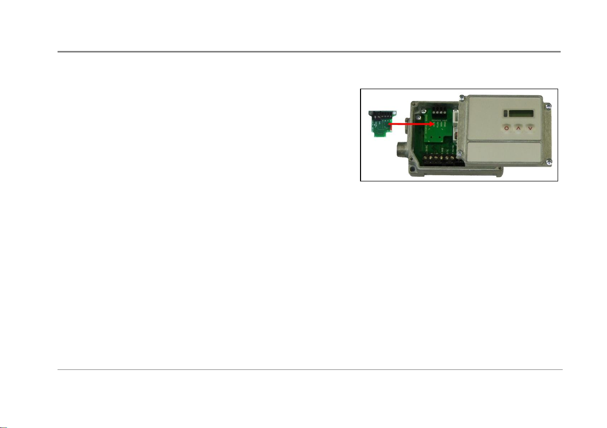
Please plug the RS485-interface board into the place provided, which is located beside the display. In the correct position the holes of the
RS485-interface match with the thread holes of the CT box.
Now press the RS485-interface down to connect it with the CT. Use both M3x5 screws for fixing the board.
The RS485-interface provides a 2-wire half-duplex mode. Please connect terminal A of the interface with terminal A of the next RS485-
interface and so on. With the B terminals proceed as well. Exchange the blind screw on each CT box by the cable gland.
Make sure, that you always connect A to A and B to B, not reverse. You may run up to 32 CT units on one RS485-USB-adapter.
The 120R-switch has to be turned to ON at one of the connected CT units only.
Each CT unit connected to the RS485 needs a different multidrop address (1...32). Please adjust the address by pressing the mode
button until M xx appears in the display. Using the Up- and Down-keys you can change the shown address (xx). The address can also be
changed with the software. The setting for baud rate in the software must be the same as on the CT unit.
Stecken Sie die RS485-Interface-Platine in die dafür vorgesehene Aufnahme im CT, welche sich neben der Anzeige befindet. Die richtige
Lage ist erreicht, wenn die Schraubenlöcher des RS485-Interface mit denen des CT übereinstimmen.
ACCTRS485-MAD-ED2016-10-A
I
Page 2

ACCTRS485USBK / ACCTRS485B RS485-Interface-Kit
EG-Konformitätserklärung / EU Declaration
Das Produkt entspricht den Anforderungen der EMV-Richtlinie 2014/30/EU und der Niederspannungsrichtlinie 2014/35/EU /
The product meets the provisions of the EMC Directive 2014/30/EU and the Low Voltage Directive 2014/35/EU.
EMV Anforderungen / EMC General Requirements:
EN 61326-1:2013 (Grundlegende Prüfanforderungen / Basic requirements)
EN 61326-2-3:2013
Gerätesicherheit von Messgeräten / Safety of measurement devices:
EN 61010-1:2010
Dieses Produkt erfüllt die Vorschriften der Richtlinie 2011/65/EU (RoHS) des Europäischen Parlaments und des Rates vom
8. Juni 2011 zur Beschränkung der Verwendung bestimmter gefährlicher Stoffe in Elektro- und Elektronikgeräten.
This product is in conformity with Directive 2011/65/EU (RoHS) of the European Parliament and of the Council of 8 June 2011
on the restriction of the use of certain hazardous substances in electrical and electronic equipment.
Drücken Sie die Platine nun nach unten, um die Kontaktierung zu erreichen. Befestigen Sie die RS485-Interface-Platine bitte mittels der
beiden mitgelieferten Schrauben M3x5 im Elektronikbox-Gehäuse.
Das RS485-Interface arbeitet im 2-Draht Halb-Duplex-Modus. Verbinden Sie Anschluss A vom Interface mit Anschluss A des nächsten
CT usw. Mit Anschluss B verfahren Sie ebenso. Tauschen Sie die Blindverschraubung an jeder CT-Box gegen die Kabelverschraubung.
Die Anschlüsse A und B dürfen nicht vertauscht werden. Es können bis zu 32 CT-Sensoren an einen RS485-USB-Adapter
angeschlossen werden. Setzen Sie bitte nur an einem der angeschlossenen CT den 120R-Schalter auf ON.
Jeder CT benötigt eine unterschiedliche Multidrop-Adresse (1...32). Betätigen Sie die Mode-Taste, bis M xx im Display erscheint. Mit den
Up- und Down-Tasten kann nun die angezeigte Adresse geändert werden (xx). Die Adresse kann auch mit der Software geändert
werden. In der Software muss die gleiche Baudrate wie am CT eingestellt werden.
ACCTRS485-MAD-ED2016-10-A
II
 Loading...