

OPTREX DMF-50887NCJU-FW-1 Datasheet
DMF-50887NCJU-FW-1 (AB) No.99-0032 OPTREX CORPORATION Page 1/19
OPTREX
Type No.
*******
Feb 22, 1998
First Edition
Final Revision
Quality Assurance Div.
Production Div.
Checked by
Checked by
Approved by
Production Div.
Design Engineering Div.
Prepared by
LCD Module Specification
DMF-50887NCJU-FW-1
DMF-50887NCJU-FW-1DMF-50887NCJU-FW-1
DMF-50887NCJU-FW-1
Table of Contents
1. General Specifications .............................................................................2
2. Electrical Specifications...........................................................................3
3. Optical Specifications..............................................................................7
4. I/O Terminal...........................................................................................10
5. Test..........................................................................................................13
6. Appearance Standards............................................................................14
7. Code System of Production Lot ..........................................................17
8. Type Number..........................................................................................17
9. Applying Precautions .............................................................................17
10. Precautions Relating Product Handling................................................18
11. Warranty..................................................................................................19
Revision History
Rev. Date Page Comment

DMF-50887NCJU-FW-1 (AB) No.99-0032 OPTREX CORPORATION Page 2/19
OPTREX
1.General Specifications
Operating Temp.
:
min. 0℃ ~ max. 60℃
Storage Temp.
:
min. -20℃ ~ max. 70℃
Dot Pixels
:
256×3 [R.G.B] (W) × 64 (H) dots
Dot Size
:
0.097 (W) × 0.331 (H) mm
Dot Pitch
:
0.117 (W) × 0.351 (H) mm
Viewing Area
:
92.8 (W) × 25.2 (H) mm
Outline Dimensions
:
128.0 (W) × 38.5 (H) × 18.0 max. (D) mm
LCD Type
:
CTD-16303
(F-STN / Color-mode / Transmissive )
Viewing Angle
:
12:00
Data Transfer
:
8-bit parallel data transfer
Backlight
:
Cold Cathode Fluorescent Lamp (CFL) × 1
Drawings
:
Dimensional Outline UE-37502
DMF-50887NCJU-FW-1 (AB) No.99-0032 OPTREX CORPORATION Page 3/19
OPTREX
2.Electrical Specifications
2.1.Absolute Maximum Ratings
V
SS
=0V
Parameter Symbol Conditions Min. Max. Units
Supply Voltage V
CC1-VSS
V
CC2-VSS
-
-0.3 6.0 V
Supply Voltage
(Contrast)
V
CONT-VSS
-
-0.3 6.0 V
Input Voltage VI
-
-0.3 V
CC1
V
Output Voltage VO
-
-0.3 V
CC1
V
2.2.DC Characteristics
Ta=25℃, V
SS
=0V
Parameter Symbol Conditions Min. Typ. Max. Units
Supply Voltage V
CC1-VSS
V
CC2-VSS
-
4.5 5.0 5.5 V
Supply Voltage
(Contrast)
V
CONT-VSS
-
0.5 2.5 4.5 V
High Level
Input Voltage
VIH V
CC1
=5.5V
2.0
-
V
CC1
V
Low Level
Input Voltage
VIL V
CC1
=4.5V
-
-
0.8 V
High Level
Output Voltage
VOH IOH=-8mA
Apply to DB0~DB15
V
CC1
-0.4
-
-
V
Low Level
Output Voltage
VOL IOL=8mA
Apply to DB0~DB15
0
-
0.4 V
High Level
Output Voltage
VOH IOH=-12mA
Apply to READY
V
CC1
-0.4
-
-
V
Low Level
Output Voltage
VOL IOL=12mA
Apply to READY
-
-
0.4 V
Frequency
f
osc
-
-
10 - MHz
Supply Current I
CC
Note1
V
CC1-VSS
=5.0V
V
CC2-VSS
=5.0V
-
40 60 mA
Note1:ICC=I
CC1+ICC2
DMF-50887NCJU-FW-1 (AB) No.99-0032 OPTREX CORPORATION Page 4/19
OPTREX
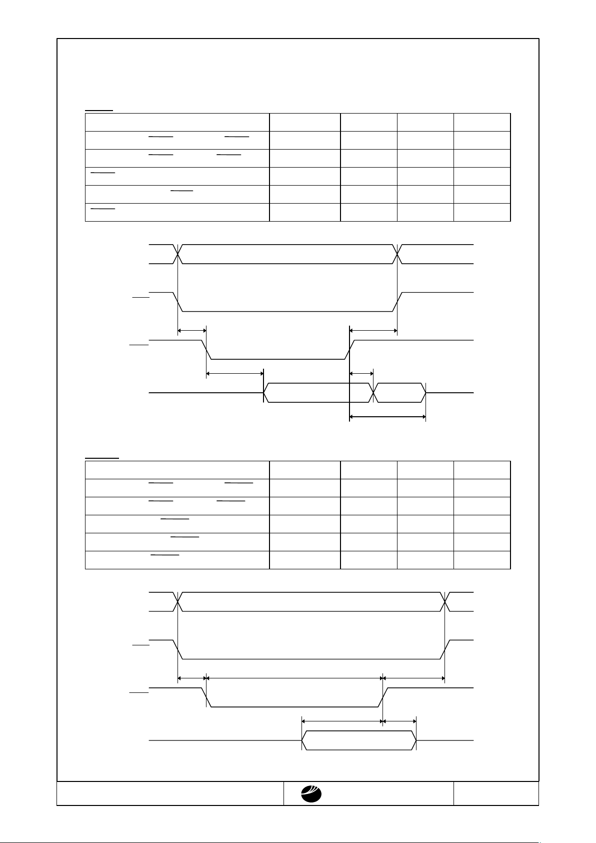
2.3.AC Characteristics
2.3.1.Read/Write Operation Sequence
READ
V
CC1
=4.5~5.5V
Parameter Symbol Min. Max. Units
AB[15:0] and IOCS valid before IORD↓
t
1
0 - ns
AB[15:0] and IOCS hold from IORD↑
t
2
10 - ns
IORD↓ to DB[7:0] valid
t
3
-
40 ns
DB[7:0] hold from IORD↑
t
4
-
15 ns
IORD↑ to DB[7:0] Hi-z delay
t
5
-
25 ns
WRITE
V
CC1
=4.5~5.5V
Parameter Symbol Min. Max. Units
AB[15:0] and IOCS valid before IOWR↓
t
1
0 - ns
AB[15:0] and IOCS hold from IOWR↑
t
2
10 - ns
DB[7:0] setup to IOWR↑
t
3
10 - ns
DB[7:0] hold from IOWR↑
t
4
10 - ns
Pulse width of IOWR
t
5
20 - ns
IORD
IOCS
Hi-zHi-z
VALID
VALIDAB[15:0]
DB[0:7]
t
3
t
4
t
2
t
1
t
5
IOWR
IOCS
AB[15:0]
VALID
VALID
Hi-ZHi-Z
DB[0:7]
t
4
t
3
t
2
t
5
t
1
DMF-50887NCJU-FW-1 (AB) No.99-0032 OPTREX CORPORATION Page 5/19
OPTREX
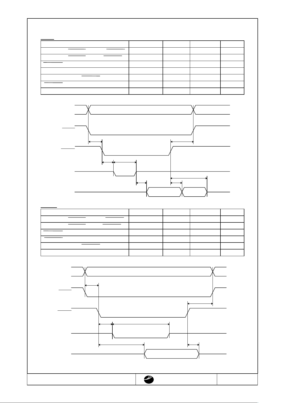
2.3.2.Read/Write Operation Sequence (VRAM)
READ
V
CC1
=4.5~5.5V
Parameter S
y
mbol Min. Max. Units
AB[15:0] and MEMCS valid before MEMRD↓
t
0 - ns
AB[15:0] and MEMCS hold from MEMRD ↑
t
0 - ns
MEMRD↓ to READY↓
t
3
-
20 ns
READY↑ to DB[7:0] valid
t
-
10 ns
DB[7:0] hold from MEMRD↑
t
5
-
10 ns
MEMRD↑ to DB[7:0] Hi-z delay
t
6
-
20 ns
READY negated pluse width
t
-
3.5×MCLK+10 ns
Where MCLK=1/fosc or 2/fosc depending on which display mode the chip is in. (See section 2.3.3.)
WRITE
V
CC1
=4.5~5.5V
AB[15:0] and MEMCS valid before MEMWR↓
t
1
0 - ns
AB[15:0] and MEMCS hold from MEMWR↑
t
0 - ns
MEMWR↓ to READY↓
t
-
20 ns
MEMWR↓ to DB[7:0] valid
t
4
-
MCLK-20 ns
DB[7:0] hold from MEMWR↑
t
5
0 - ns
READY negated pluse width
t
-
3.5×MCLK+10 ns
Where MCLK=1/fosc or 2/fosc depending on which display mode the chip is in. (See section 2.3.3.)
READY
MEMRD
MEMCS
Hi-z
Hi-z
Hi-z
Hi-z
VALID
VALIDAB[15:0]
DB[0:7]
t
4
t
5
t
2
t
7
t
3
t
1
t
6
READY
MEMCS
AB[15:0]
VALID
Hi-Z
Hi-ZHi-Z
Hi-Z
DB[0:7]
VALID
t
5
t
4
t
2
t
1
MEMWR
t
6
t
3
DMF-50887NCJU-FW-1 (AB) No.99-0032 OPTREX CORPORATION Page 6/19
OPTREX
2.3.3.SRAM Access Time
8-bit Display Memory Interface
Display Mode Access time
16-level colors Access time≦1/fosc-25ns
4-level colors Access time≦2/fosc-25ns
Black-and-White(BW) Access time≦2/fosc-25ns
 Loading...