

OPTREX DMC-50747NF-AK Datasheet
First Edition
Jul 9, 2001
OP T R E X
Type No.
LCD Module Technical Specification
DMC-50747NF-AK
Table of Contents
1. General Specifications
2. Electrical Specifications
3. Optical Specifications
4. I/ O Terminal
5. Test
..............................................................................................................................................................................................11
............................................................................................................................................................................9
6. Appearance Standards
7. Code System of Production Lot
8. Applying Precautions
9. Precautions Relating Product Handling
10 . Warranty
................................................................................................................................................................................17
.....................................................................................................................................................2
.................................................................................................................................................3
......................................................................................................................................................7
..................................................................................................................................................12
......................................................................................................................................................15
Final Revision
******
Approved by (Production
Checked by (Quality Assurance
Checked by (Design Engineering Div.)
Prepared by (Production Div.)
............................................................................................................................15
............................................................................................................16
Revision History
Rev. Date Page Comment
DMC-50747NF-AK (AK) No.2001-0124 OPTREX CORPORATION Page 1/ 17

1. General Specificat ions
Operating Temp. : min. 0°C ~ max. 50°C
Storage Temp. : min. - 20°C ~ max. 70°C
Display Format : 16 characters×2 lines
Display Fonts : 5×7 dots ( 1 character )
Viewing Area : 60.2 (W)×16.6 (H) mm
Outline Dimensions : 64.2 (W)×27.6 (H)×2.2 max. (D) mm
* Without FPC
Weight : 10g max.
LCD Type : NRD-17533
( F- STN / Black&White- mode / Reflective )
Viewing Angle : 6:00
Data Transfer : 8-bit parallel data transfer
Backlight : None
Additional Spec. : I/ O FPC Type
Drawings : Dimensional Outline UE-310783
DMC-50747NF-AK (AK) No. 2001-0124 OPTREX CORPORATION Page 2/17
2.Electrical Specificat ions
2.1.Absolute Maximum Ratings
VSS=0V
Parameter Symbol Conditions Min. Max. Units
Supply Voltage
VDD-V
SS
- -0.3 6.0 V
(Logic)
Supply Voltage
VDD-V
OUT
V5=V
OUT
-0.3 16.0 V
(LCD Drive)
Input Voltage V
I
- -0.3 VDD+0.3 V
2.2.DC Characteristics
Ta=25°C, VSS=0V
Parameter Symbol Conditions Min. Typ. Max. Units
Supply Voltage
VDD-V
SS
- 2.4 3.0 3.6 V
(Logic)
Supply Voltage
VDD-V
OUT
Shown in 3.1 V
(LCD Drive)
High Level
V
IH
VDD=3.0V±10% 0.8´V
DD
- V
DD
Input Voltage
V
Low Level
V
IL
VDD=3.0V±10% 0 - 0.2´V
Input Voltage
Supply Current I
DD
VDD-VSS=3.0V
Note.1
Note.1 : Triple boosting state and checker pattern.
DD
V
- 0.05 0.1 mA
DMC-50747NF-AK (AK) No. 2001-0124 OPTREX CORPORATION Page 3/17
2.3.AC Characteristics
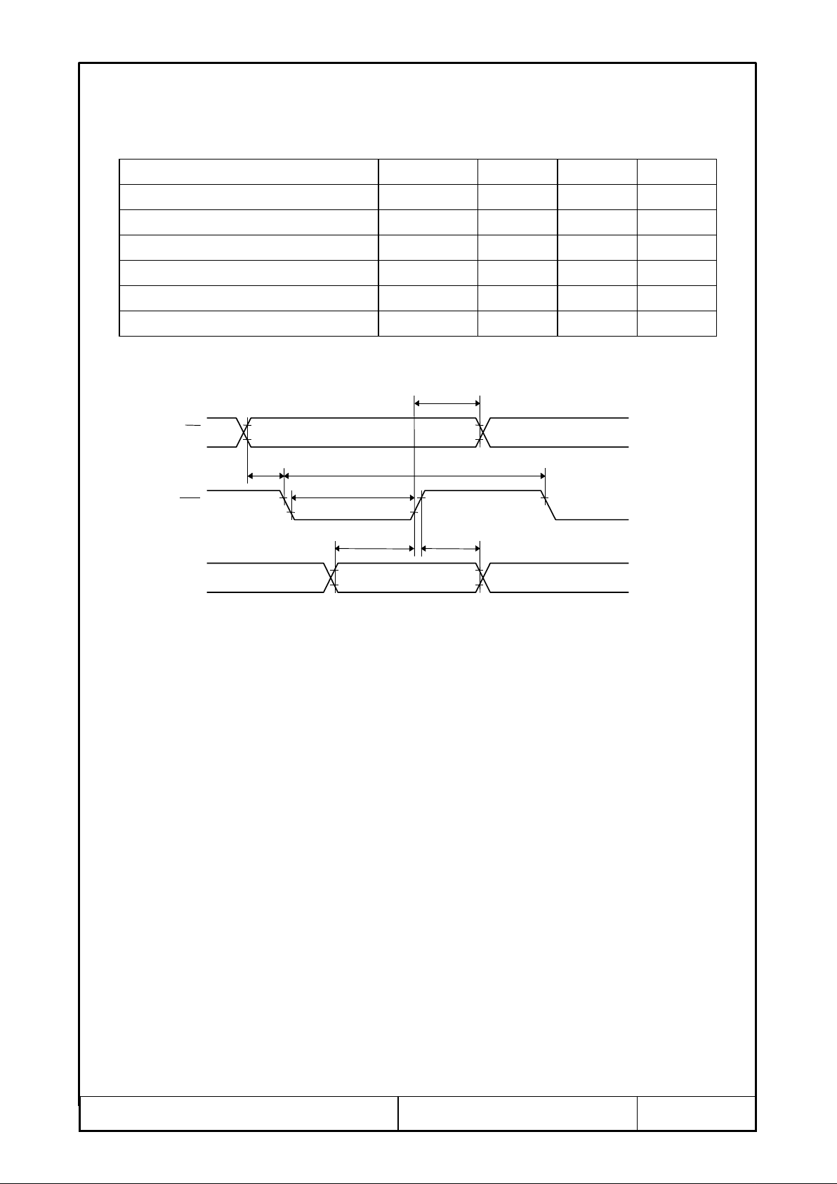
2.3.1.System Bus Write Characteristics 1 (80 series MPU)
Parameter Symbol Min. Max. Units
VDD=3.0V±10%
System Cycle Time
Address Setup Time
Address Hold Time
Data Setup Time
Data Hold Time
Control Pulse Width
t
CYC
t
t
t
t
t
AW
AH
DS
DH
CC
500 - ns
60 - ns
30 - ns
100 - ns
50 - ns
100 - ns
Note 1 : For the rise and fall of an input signal, set a value not exceeding 25ns.
Note 2 : Every timing is specified on the basis of 20%and 80%of VDD.
AH
t
A0, CS
CC
CYC
t
DS
t
DH
t
D0~D7
WR
AW
t
t
DMC-50747NF-AK (AK) No. 2001-0124 OPTREX CORPORATION Page 4/17

2.3.2.System Bus Write Characteristics 2 (68 series MPU)
Parameter Symbol Min. Max. Units
VDD=3.0V±10%
System Cycle Time
Address Setup Time
Address Hold Time
Data Setup Time
Data Hold Time
Control Pulse Width
t
CYC
t
t
t
t
t
AW
AH
DS
DH
CC
500 - ns
60 - ns
30 - ns
100 - ns
50 - ns
100 - ns
Note 1 : For the rise and fall of an input signal, set a value not exceeding 25ns.
Note 2 : Every timing is specified on the basis of 20%and 80%of VDD.
CYC
t
E
AH
t
DH
t
A0, CS
t
AW
t
EW
DS
t
D0~D7
DMC-50747NF-AK (AK) No. 2001-0124 OPTREX CORPORATION Page 5/17
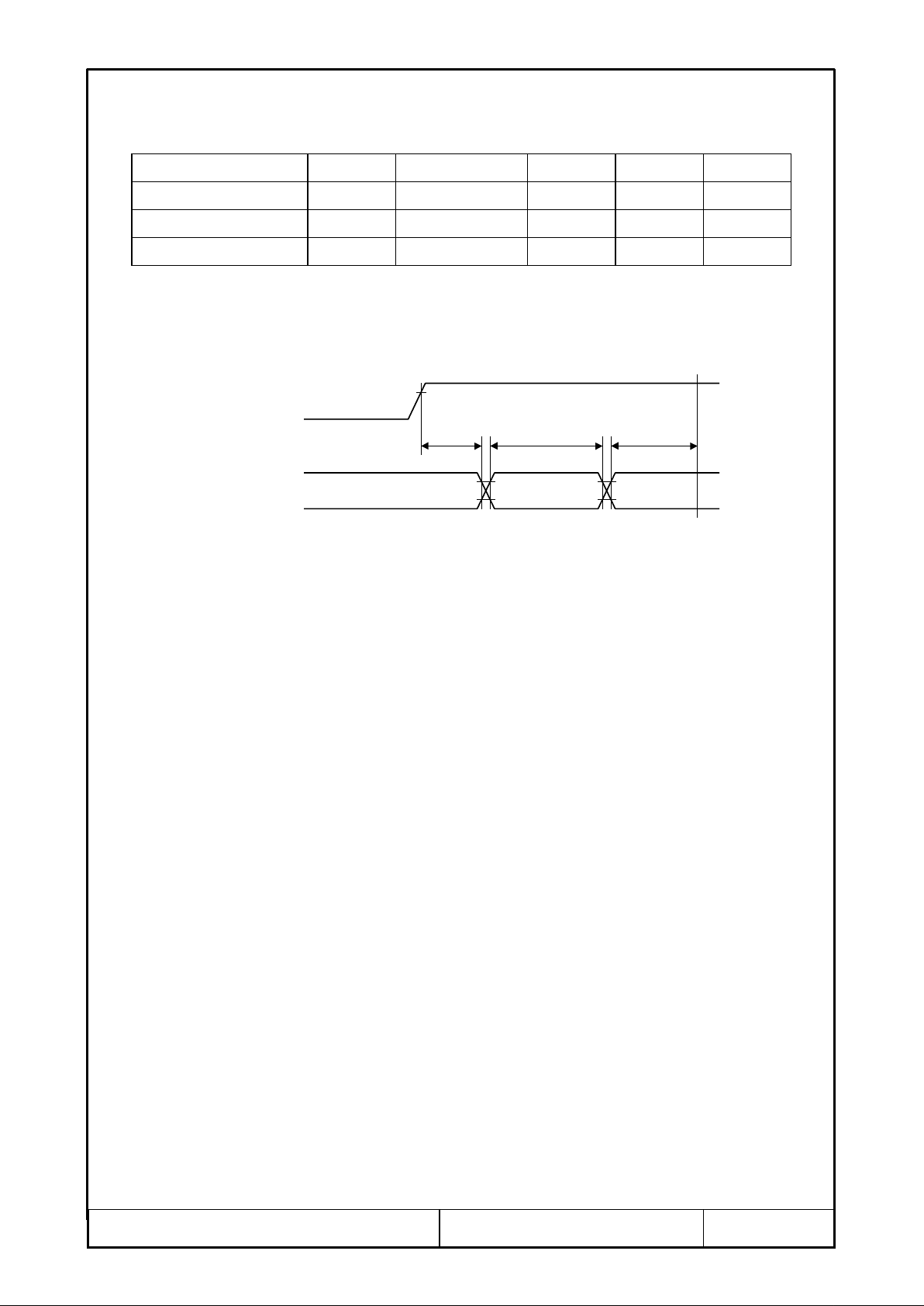
2.3.3.Reset Timing
VDD=3.0V±10%
Parameter Symbol Conditions Min. Max. Units
t
t
t
RES
R
RW
Note 1 1.0 Note 2 10 -
m
m
Note 2 50 - ns
t
R
s
s
.
Reset Time
Reset Pulse Width
Reset Start Time
Note 1 :
t
( Reset Time ) indicates the internal circuit reset completion time from the edge
R
of the RES signal. Accordingly, it usually enters the operating state after
Note 2 : Specifies the minimum pulse width of the RES signal. It is reset when a signal having
the pulse width greater than
VDD
PowerSupply
VSS
t
is entered.
RW
tRW tRtRES
VDD
RES
VSS
All signal timings are based on 20%and80%of VDD signals.
DMC-50747NF-AK (AK) No. 2001-0124 OPTREX CORPORATION Page 6/17
 Loading...