

OptoTest OP415 Instruction Manual

www.optotest.com
1.805.987.1700
Polarity Analyzer
Instruction Manual
OP415

1 of 29
Contacting OptoTest Corporation
1.805.987.1700 (7:30 a.m. to 5 p.m. PST)
www.optotest.com
engineering@optotest.com
OptoTest Corp.
4750 Calle Quetzal
Camarillo, CA 93012 USA
Notice of Proprietary Rights
The design concepts and engineering details embodied in this manual, which are
the property of OptoTest Corporation, are to be maintained in strict condence. No
element or detail of this manual is to be spuriously used or disclosed without the
express written permission of OptoTest Corporation. All rights are reserved. No part
of this publication may be reproduced, stored in a retrieval system, or transmitted
in any form or by any means, electronic, mechanical, photocopying, recording, or
otherwise, without prior written permission from OptoTest Corporation.
COPYRIGHT © 2018 by OptoTest Corp
ALL RIGHTS RESERVED
PRINTED IN THE UNITED STATES OF AMERICA
MnOP415-RevA

OP415
2 of 29
Table of Contents
Overview 3
Initial Preparation 4
Unpacking and Inspection 4
Damaged in Shipment 4
Standard Contents 4
Denition of Specications 5
Nomenclature 8
How to Navigate the User Interface 9
Front Panel Operation 10
Map Screen 10
Create Type Screen 14
Files Screen 16
Settings Screen 17
Example 1: Running a Test 20
Example 2: Create a New Type 22
Example 3: Create Power Level Reference 24
Example 4: Testing 12-Fiber Polarity 25
Warranty Information 27

OP415
3 of 29
Overview
The OP415 is designed to analyze the polarity and output quality of MTP®/MPO cable
assemblies of up to 24 bers. Individual power meters allow for testing 24 ber polarity
in 1.5 seconds and fewer channel counts in fractions of that time. The unit comes
pre-loaded with 12 and 24 ber types A, B, and C; along with the ability to create and
store new types. In addition, the unit is able to check the quality of a cable and store
test results, with internal storage for up to 256 cable types and test results.
The full color touchscreen display, compact design, and lightning fast test time make
the OP415 Polarity Analyzer the ideal test solution for environments where MTP/MPO
cables are manufactured or utilized.
The OP415 is able to analyze polarity for:
• Type A (12, 24)
• Type B (12,24)
• Type C (12,24)
• 8,12,16, 24 ber
• Custom Fiber Mappings

OP415
4 of 29
Initial Preparation
Unpacking and Inspection
The unit was carefully inspected; mechanically, electrically, and optically before shipment.
When received, the shipping carton should contain the items listed in Standard
Contents; account for and inspect each item. In the event of a damaged instrument,
write or call OptoTest Corp, California.
Note: Be aware that accessories such as detector adapters, remote head detectors,
and high performance reference cables will be located inside a small box labeled
“Accessories Inside”. If this box is not included with the original shipment, contact
OptoTest or their nearest distributor.
Please retain the shipping container in case re-shipment is required for any reason.
Damaged In Shipment
All instruments are shipped F.O.B. Camarillo when ordered from OptoTest.
If you receive a damaged instrument you should:
1. Report the damage to your shipper immediately.
2. Inform OptoTest Corporation.
3. Save all shipping cartons.
Failure to follow this procedure may aect your claim for compensation.
Standard Contents
1. Model OP415 Polarity Analyzer
2. 9V Power Supply and Power Cord
3. USB A-B cable
4. Certicate of Conformance
5. Instruction Manual
6. USB drive with applicable software and documentation (if ordered)

OP415
5 of 29
Definition of Specifications
Dynamic Range
The dynamic range, or measurement range, of the optical power meter spans from the
maximal power level the instrument can measure, without major saturation to the detector,
to the minimal power level where the thermal noise of the detector becomes greater
than the current produced by the incident light. For accurate power measurements, it
is NOT recommended to measure power levels at either end of the dynamic range (see
Linearity). The dynamic range is measured by comparing the absolute measured power
against a reference power. When the difference between the two exceeds 1dB either
end of the dynamic range has been reached.
Linearity
Photodetectors are, by nature, very linear over a wide range of optical input powers,
but the power meter electronics can affect the overall system linearity. The power meter
linearity is characterized and specified to know the measurement accuracy and linearity
over the full dynamic range. For accurate insertion loss measurements only power levels
that fall within the range with the best linearity (+/-0.05dB or better) should be measured.
Calibration Wavelength
The calibration wavelengths are the nominal wavelengths of the instrument’s calibration
points. The exact wavelength of each particular calibration is stated in the Certificate of
Calibration.
Calibration Traceability
The detector’s absolute calibration data is directly traceable to N.I.S.T. at the specified
calibration wavelength and the specified power level, typically -10dBm.
OP415
6 of 29
Absolute Accuracy
The absolute accuracy specification includes the total measurement uncertainties
involved in the calibration process including the transfer of the absolute power standard
from N.I.S.T. (Contact OptoTest for the detailed chain of uncertainties)
Optical Power Meter, Channel Performance
For multichannel instruments, the power meter circuit converts and digitizes the optical
power level with the given sampling interval. Changes in light levels such as modulation
will be averaged within that sampling interval.
Instrument, Warm-up Time
Optical power meters, in general, do not need any warm-up time unless the instrument
has to acclimate to a changing environment. In order to calibrate the instrument or to
perform stable measurements, the instrument should be acclimated for 15 minutes for
each 5ºC of temperature differential. For example, if the instrument was stored at 18ºC
and brought into an environment of 28ºC the instrument should be allowed to warm-up
for 30 minutes.
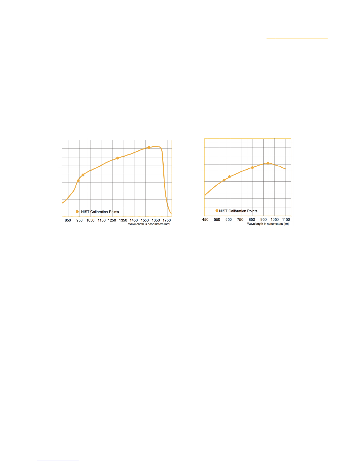
Responsivity of InGaAs Detectors Responsivity of Silicon Detectors
Note that other detector types are available such as IN5 (5mm InGaAs) IN10 (10mm InGaAs) as
well as WSR (wide spectral range) and might exhibit a different spectral responsivity.
Definition of Specifications
Spectral Responsivity
Depending on the detector type, InGaAs (Indium Gallium Arsenide) or Silicon the
spectral responsivity, the efficiency of the detector to convert optical power into
electrical current, changes with wavelength.

OP415
7 of 29
Definition of Specifications
Recommended Recalibration Period
This is the recommended time period for re-calibration in order to maintain accuracy
specifications. The recommendation is made based upon statistics on detector aging.
However, it is up to the metrology policies and procedures within each company to
define the calibration cycles on optical power meters.
Optical Power Meter, Fiber Compatibility
The amount of areal coverage of the detector, or the portion of the light emitted from
the fiber being measured, depends on the mechanical features of the optical interface,
the active area of the detector and the numerical aperture (NA) of the fiber. A fiber
with a large NA, for example 100/140 multimode fiber, may not under fill a small area
detector hence the absolute power reading will be less than actual.
Reference Cable
The reference cable is the cable with which the DUTs will be measured against. Typically
reference cables are required to be of a defined quality with a specified connector/
endface polish.
Instrument, Environmental
Operating Temperature: This is the temperature range in which the instrument will
conform to the specifications after the specified warm-up time.
Storage Temperature: This is the temperature range at which the instrument can
be stored with the power off without any damage or any loss of specification to the
instrument. It is required that the instrument be brought back to within the operating
temperature range before it is turned on.
Humidity: The relative non-condensing humidity levels allowed in the operating
temperature range.

OP415
8 of 29
Nomenclature
Touchscreen Display
Power Button
(Keyed)
Laser Emission
Safety Label
Removable
Front Panel
Removable
Feet
Source
Port
Receive
Port
OP415
9 of 29
Map Screen
Create Screen
File Screen
Settings Screen
How to Navigate the User Interface
The OP415 is equipped with a full color touchscreen display, eliminating the need for
physical buttons and allowing for increased functionality through the front panel.
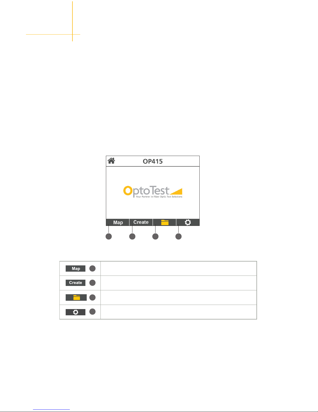
Home Screen
At startup, the unit loads the Home screen. From here the user can select the Map
screen, Create screen, File screen or the Settings screen.
Note: There is an option in the Settings to go directly to the Map screen at power up.
1
2
3
4
1 2 3 4
 Loading...