

Optoma EP1080, DX1080, OP1990, VE810, PV8530 Service Manual
...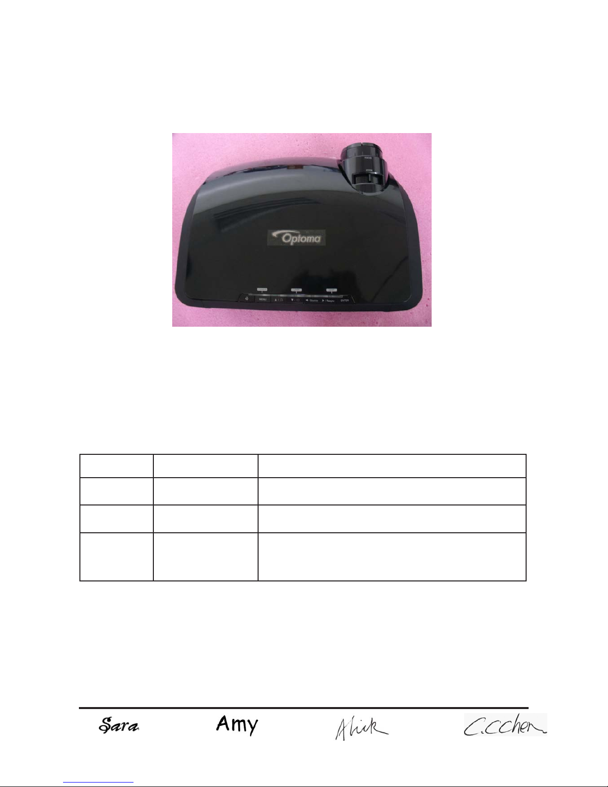
SERVICE MANUAL
SI : TSE: Check: Approved:
Date Revise Version Description
2008.09.10 V1.0 Initial Issue
2008.09.22 V2.0 Modify Chapter 1 and add Chapter 7
2009.03.13 V3.0
Add EP1080 extended models: DX1080, OP1990,
VE810, DP7290, PV8530, P350, TX1080 and amend
the method of getting into FW mode in Chapter 5
EP1080/DX1080/OP1990/VE810/DP7290/
PV8530/P350/TX1080
Copyright March, 2009. All Rights Reserved P/N:36.8BH03G001

EP1080 Series
Condential
I
Preface
This manual is applied to EP1080 Series projection system. The manual gives you a brief
description of basic technical information to help in service and maintain the product.
Your customers will appreciate the quick response time when you immediately identify
problems that occur with our products. We expect your customers will appreciate the
service that you offer them.
This manual is for technicians and people who have an electronic background. Please
send the product back to the distributor for repairing and do not attempt to do anything that
is complex or is not mentioned in the troubleshooting.
Notice: The information found in this manual is subject to change without prior notice. Any
subsequent changes made to the data herein will be incorporated in future edition.
EP1080 Series Service Manual
Copyright March.2009
All Rights Reserved
Manual Version 3.0

EP1080 Series
Condential
II
Table of Content
Chapter 1 Introduction
Highlight 1-1
Compatible Mode 1-4
Chapter 2 Disassembly Process
Equipment Needed & Product Overview 2-1
Disassemble Lamp Cover Module 2-2
Disassemble Lamp Module 2-2
Disassemble Lens Shelter 2-3
Disassemble Top Cover Module 2-3
Disassemble Keypad Board Module 2-4
Disassemble Vent 2-5
Disassemble Rear Cover Module 2-7
Disassemble Formatter Board and Scaler Board Module 2-8
Disassemble Air Ductor 2-10
Disassemble System Fan Module 2-10
Disassemble Left Shielding Module 2-12
Disassemble Engine Module 2-13
Disassemble Color Wheel Module 2-14
Disassemble DMD Chip 2-15
Disassemble LVPS Module 2-15
Disassemble Ballast Module 2-16
Disassemble Blower Module 2-17
Disassemble Safety Switch 2-18
Disassemble IR Sensor Board and AIR Duct 2-18

EP1080 Series
Condential
III
Disassemble Left and Right Elevator Module 2-19
Rod Adjustment 2-21
Re-write Lamp Usage Hour 2-22
Chapter 3 Troubleshooting
LED Lighting Message 3-1
Main Procedure 3-2
Chapter 4 Function Test & Alignment Procedure
Test Equipment Needed 4-1
Service Mode 4-1
OSD Reset 4-1
Test Condition 4-2
Test Inspection Procedure 4-3
PC MODE 4-3
Calibration 4-7
Optical Performance Measure 4-10
Video Performance 4-12
Network Function Test 4-14
Others 4-16
Chapter 5 Firmware Upgrade
Equipment Needed 5-1
USB Driver Setup Procedure 5-2
Firmware Upgrade Procedure 5-3

EP1080 Series
Condential
IV
Chapter 6 EDID Upgrade
EDID Introduction 6-1
Equipment Needed 6-2
Setup Procedure(VGA-2 & DVI-D Port) 6-3
EDID Key-In Procedure(VGA-2 & DVI-D Interface) 6-3
Setup Procedure(VGA-1 & HDMI Port) 6-6
EDID Key-In Procedure(VGA-1 & HDMI Interface) 6-6
Chapter 7 Network FW Upgrade
Equipment Needed 7-1
Read Projector IP 7-2
Network Setting 7-3
PC Hardware Link 7-4
Appendix A
Exploded Image I
Appendix B
SerialNumberSystemDenition XIX
PCBACodeDenition XX
EP1080 Series Condential 1-1
Chapter 1
Introduction
No Item Description
1 Dimension (L x W x H)
• 411 x 311 x 116 (mm)
2 Weight
• Unit(projector): approx. 10 lbs (< 11lb)
3 Tilt Angle
• 6 degree with elevator mechanism
4 Power Supply
• Universal AC 100--240V; 50 / 60 Hz with PFC input
• Provide for Philips 300W UHP E21.9 lamp
5 Keystone correction
• -5°~ +10° Vertical
6 Resolution
• 1920 x 1080P
7 Brightness
• 2,872 ANSI Lumens (Typical)
• 2,584 ANSI Lumens (Min.)
8 Contrast
• 1,500 :1 full on/full off (Typical)
• 1,200 :1 full on/full off (Min.)
9 Uniformity
• 70% Japan standard (Typical)
• 60% Japan Standard (Min.)
10 Throw ratio
• 1.85 – 2.22:1 distance/width
11 Projection lens
• F/ 2.6~2.89, f = 39.12~46.91 mm. 1.2X Zoomed Focal Lens.
• Offset : 136 +/- 5%
12 Color wheel
• 5 Segment, RYGWB (R80Y40G82W78B80)
13 System controller
• Dual DDP3021, DAD1000, PMD1000 for 1080p DMD
14 Lamp
• Philips 300Watt E21.9 UHP
15 Altitude
• Operating
0~2,500 ft 5°C~35°C
2,500~5,000 ft 5°C~30°C
5,000~10,000 ft 5°C~25°C
• Storage
40,000 ft
1-1 Highlight
EP1080 Series
Condential
2
No Item Description
16 Maximum Humidity
• Operating:
5 ~ 35°C, 80%RH (Max.), non-condensing
• Storage:
-20 ~ 60°C, 80%RH (Max.), non-condensing
17 Video compatibility
• NTSC: NTSC M/J, NTSC 4.43
• PAL: PAL B/D/I/G/H, PAL M, PAL N
• SECAM: SECAM B/D/G/K/L
• SDTV: 480i, 480p, 576i, 576p,
• HDTV: 720p(50Hz),720p(60Hz),1080i(50Hz),1080i(60Hz),
1080p (60Hz)
18 Input signal
• Analog RGB signal(PC)
Analog RGB 0.7Vp-p, 75 ohm
Analog RGB 1Vp-p, 75 ohm, Sync. signal
Separate TTL H,V Sync.
Composite TTL Sync.
• Video signal
Composite video 1Vp-p, 75 ohm
S-video Luminance 0.714Vp-p, 75 ohm
Chrominance 0.286Vp-p, 75 ohm
19 Temperature
• Operating: 5 ~ 35°C
• Storage: -20 ~ 60°C
20 DMD Chip
• TI DMD, Single chip 0.95” Dark Chip 1 LVDS 1080p Super
value DMD
21 Number of active dots
• 1920(H) x 1080(V)
22 Audio
• in (3.5mm) x 3 for VGA1, VGA2, DVI-D
• out (3.5mm) x 1
• in RCA(L/R) x 1 for S-video, Composite
23 Cooling System
• Advanced air ow
• One fan/ two blowers(in projector) with low system acoustic
noise level
• Temperature control circuits with adaptive voltage control fan
speed
• Max touch temperature follows UL60950 regulation
1-
Condential
1-3
No Item Description
24 Power consumption
• Full power(at normal mode):typical 400W+/-10% at 110V AC
• ECO power(at ECO mode):typical 340W +/-10% at 110V AC
• Standby mode: < 14W at 110V AC
25 Terminal
• One HDMI input connectors (Support Audio input)
• One DVI-D input
• Two VGA input
• One VGA output
• One S-Video
• One Composite Video
• One 12V relay
• Audio-in (3.5mm) x 3 for VGA1, VGA2, DVI-D
• Audio-out (3.5mm) x 1
• Audio-in RCA(L/R) x 1 for S-video, Composite
• One D-sub 9-pin RS-232 port
• USB x 1 (Type B)
• RJ-45 x 1
• One 3-pin AC power inlet port
EP1080 Series
EP1080 Series
Condential
1-2 Compatible Mode
Analog
Compatibility Resolution V-Sync [Hz]
VGA
640x350 70
640x350 85
640x400 85
640x480 60
640x480 72
640x480 75
640x480 85
720x400 70
720x400 85
SVGA
800x600 56
800x600 60
800x600 72
800x600 75
800x600 85
XGA
1024x768 60
1024x768 70
1024x768 75
1024x768 85
WXGA*
1280x720 60
1280x768 60
1280x768 85
SXGA
1280x1024 60
1280x1024 75
SXGA+ 1400x1050 60
UXGA 1600x1200 60
1-4
EP1080 Series
Condential
1-5
Compatibility Resolution V-Sync [Hz]
VGA
640x480 60
640x480 72
640x480 75
640x480 85
SVGA
800x600 60
800x600 75
800x600 85
XGA
1024x768 60
1024x768 70
1024x768 75
1024x768 85
WXGA
1280x768 60
1280x768 70
HD
1280x720 60
1280x1024 60
1280x1024 75
SXGA+ 1400x1050 60
UXGA 1600x1200 60
Digital
EP1080 Series Condential
2-1
Chapter 2
Disassembly Process
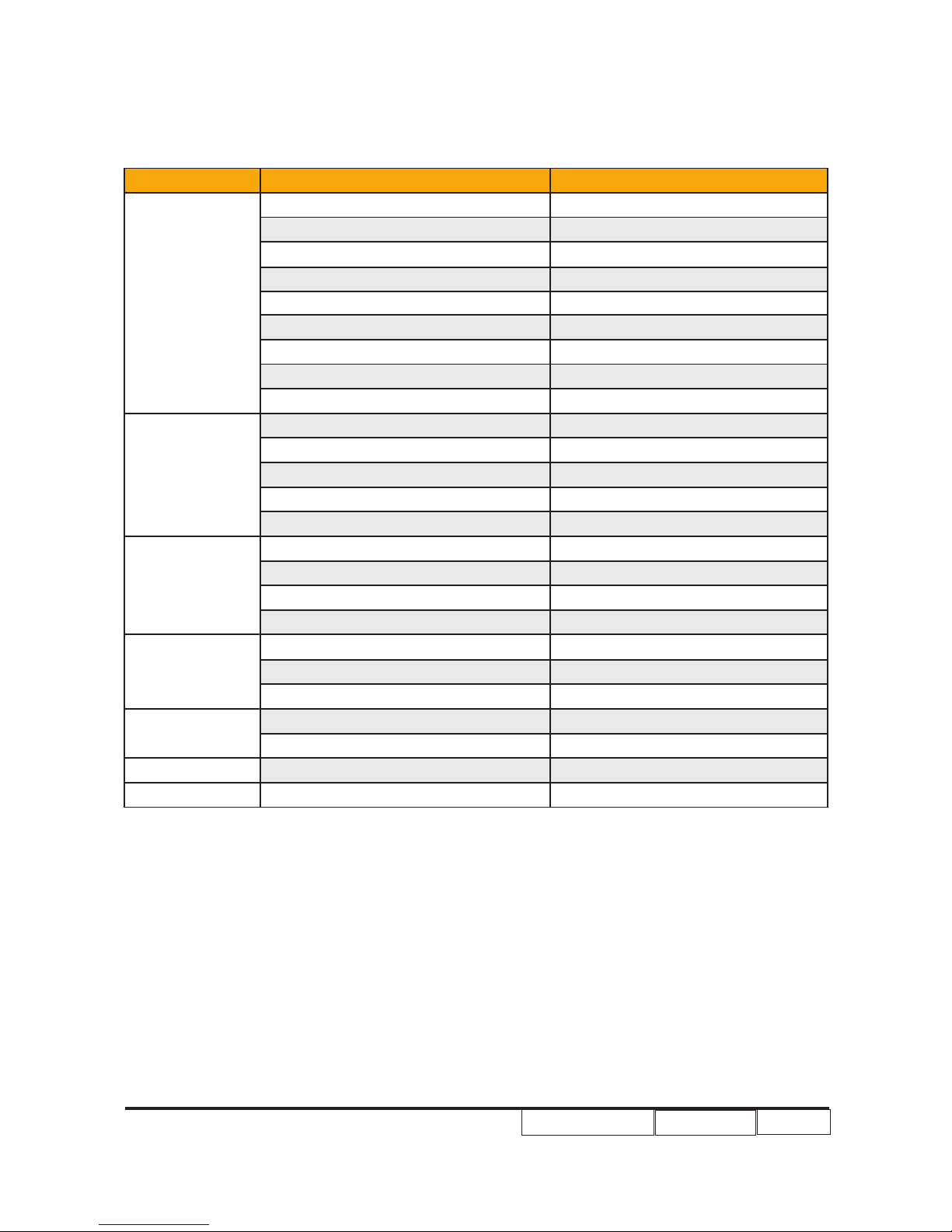
2-1 Equipment Needed & Product Overview
1. Screw Bit (+) :105
2. Screw Bit (+) :107
3. Screw Bit (-) :107
4. Hex Sleeves 5 mm
5. Tweezers
6. Projector
* Before you start: This process is protective level II. Operators should wear electrostatic chains.
* Note: - If you need to replace the scaler board, you have to record the lamp usage hour.
- As the process of EP1080 extended models disassembling is the same as EP1080, we
take EP1080 for example here.
EP1080 Series Condential 2-2
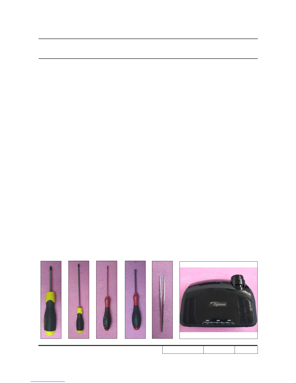
2-3 Disassemble Lamp
Module
1. Unscrew 2 screws (as red circle) on the
Lamp Module.
2. Take off Lamp Module.
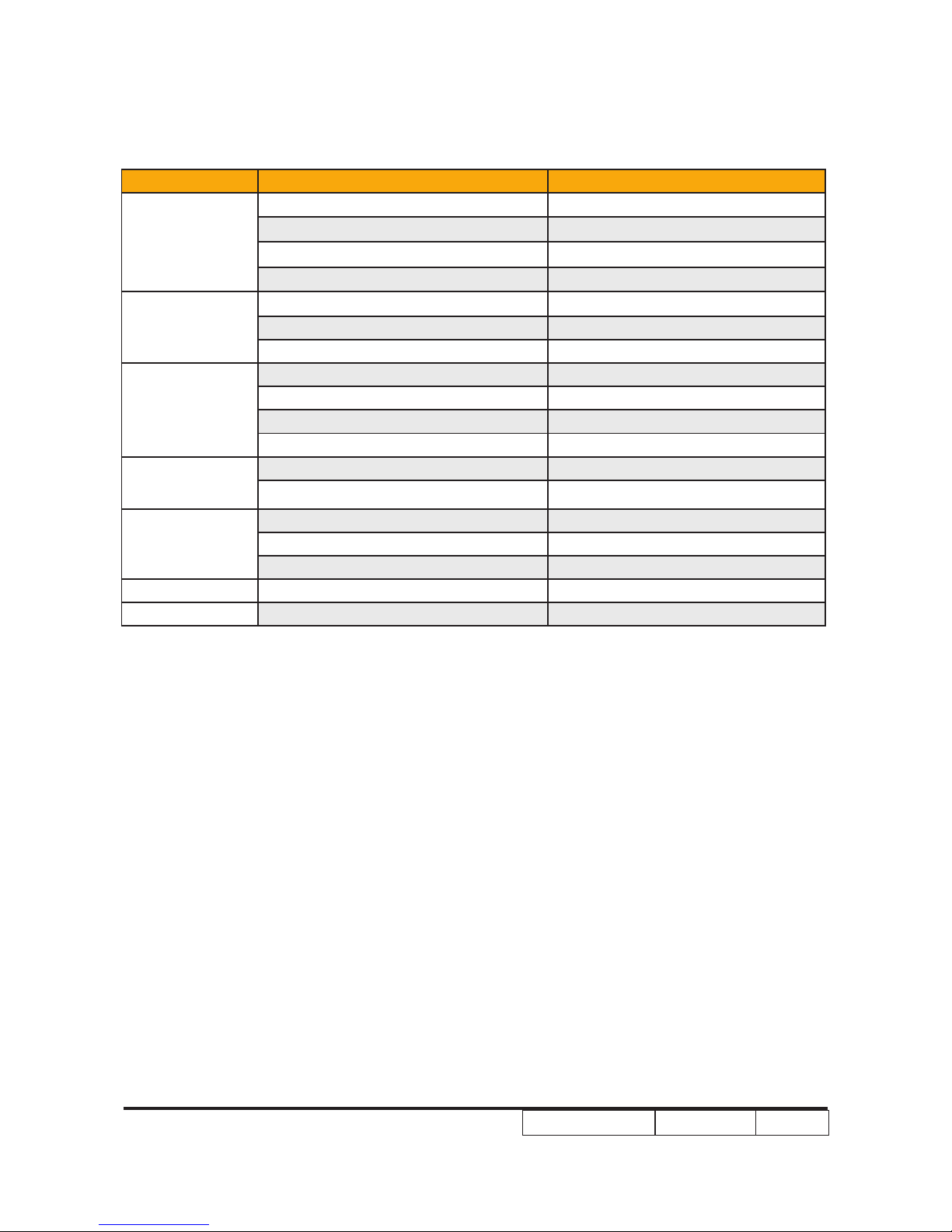
2-2 Disassemble Lamp
Cover Module
1. Unscrew 2 screws (as red circle) on the
Lamp Cover.
2. Disassemble Lamp Cover Module.
EP1080 Series Condential 2-3
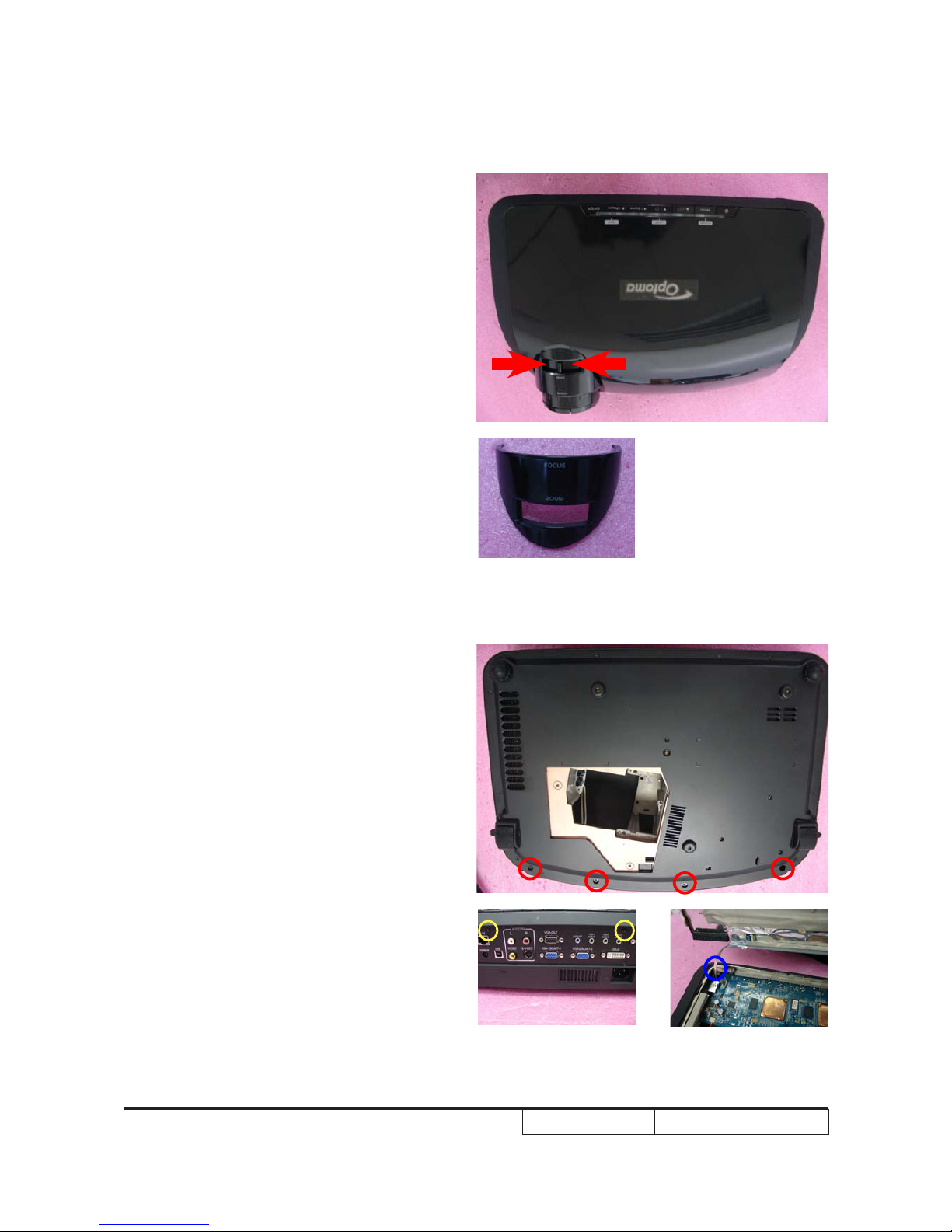
2-4 Disassemble Lens
Shelter
1. Turn the projector backside.
2. Press two sides of the Lens Shelter as
red arrow point and take it up.
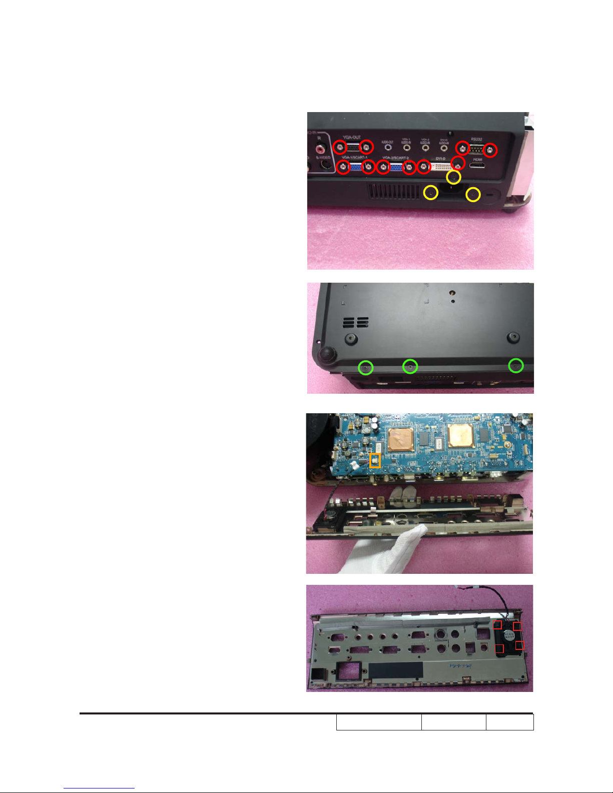
2-5 Disassemble Top Cover
Module
1. Unscrew 4 screws from the Bottom
Cover (as red circle).
2. Unscrew 2 screws from the Rear Cover
(as yellow circle).
3. Push forward to remove the Top Cover
Module.
4. Unplug 1 FPC Cable from the Scaler
Board Module (as blue circle).
EP1080 Series Condential 2-4
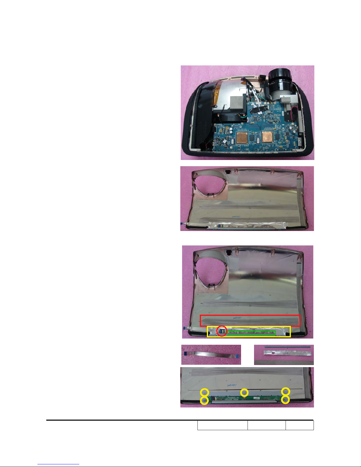
5. Disassemble the Top Cover Module.
2-6 Disassemble Keypad
Board Module
1. Unplug 1 FPC cable (as red circle).
2. Take off EMI Gasket (as green square),
EMI Type (as red square) and Keypad
Type (as yellow square).
3. Unscrew 5 screws (as yellow circle).
4. Disassemble the Keypad Board Module.
EP1080 Series Condential 2-5
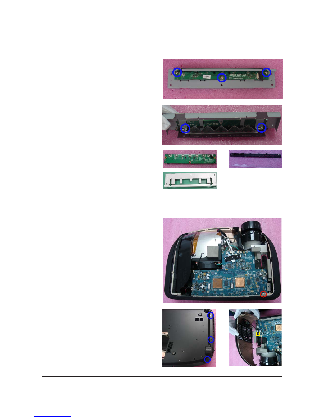
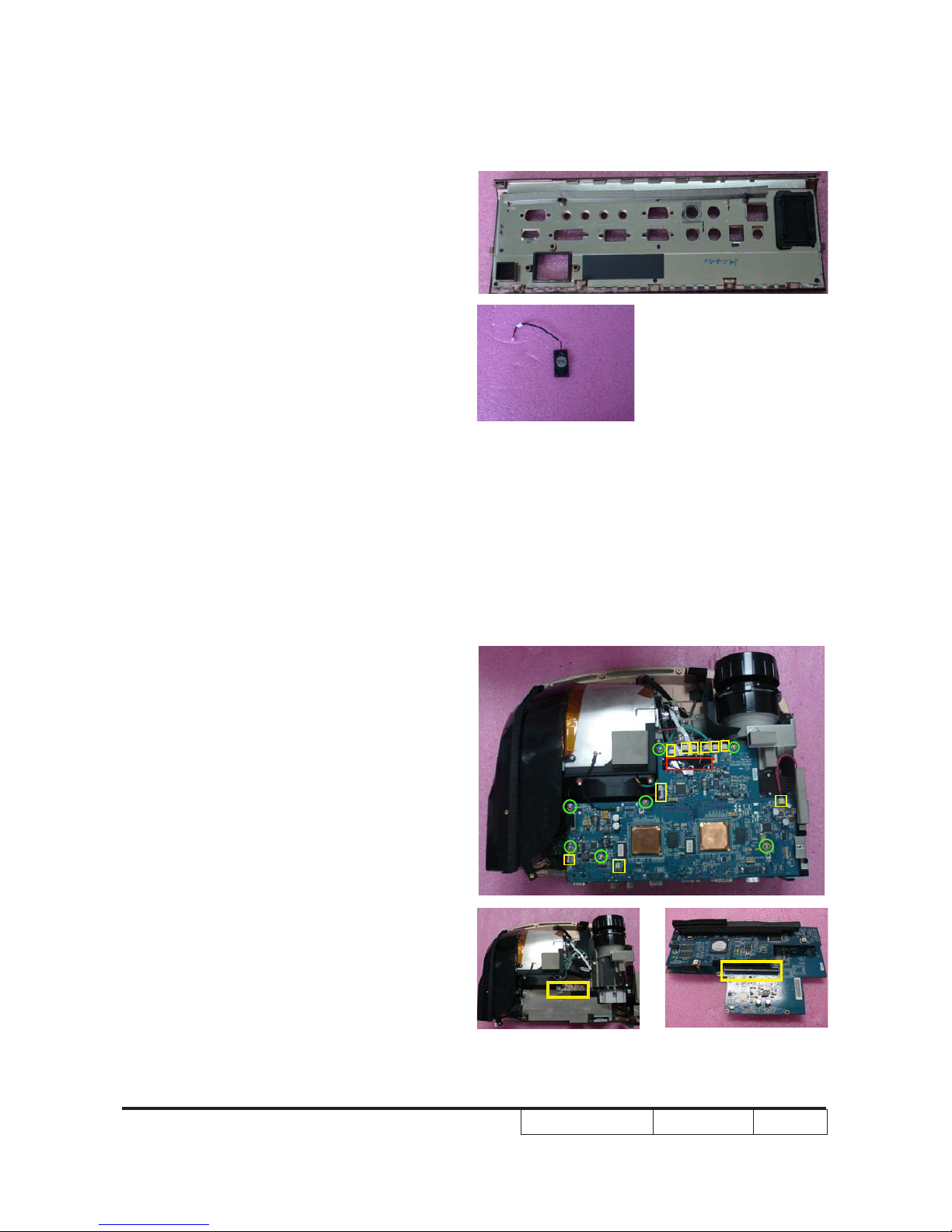
5. Unscrew 5 screws (as blue circle).
6. Separate Keypad Board,Keypad Button,
LED Transparent Bar and Keypad Brac-
ket.
2-7 Disassemble Vent
1. Unscrew 1 screw on the Left Vent (as red
circle).
2. Turn the projector to backside and
unscrew 3 screws (as blue circle).
3. Uplug 1 connector (as yellow square) and
remove the Left Vent.
EP1080 Series Condential 2-6
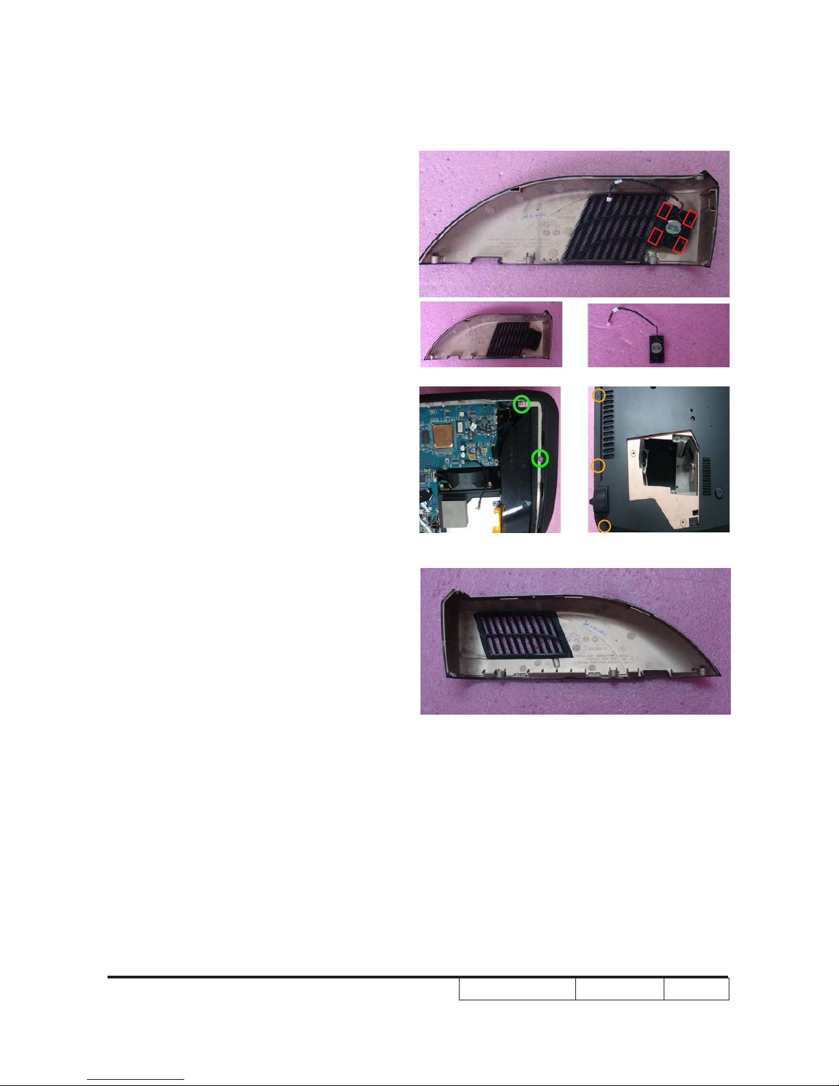
4. Unplug 4 clips (as red sqaure) and
remove the Speaker.
5. Unscrew 2 screws on the Right Vent
(as green circle).
6. Turn the projector backside and unscrew
3 screws (as orange circle).
7. Remove the Right Vent.
EP1080 Series Condential 2-7
2-8 Disassemble Rear Cover
Module
1. Unscrew 10 hex screws (as red circle)
and 3 usual screws (as yellow circle).
2. Turn the projector backside and unscrew
3 screws (as green circle).
3. Unplug the connector (as orange sqaure)
and remove the Rear Cover.
4. Unplug 4 clips (as red sqaure).
EP1080 Series Condential 2-8
2-9 Disassemble Formatter
Board and Scaler Board
Module
1. Take off mylar (as red square).
2. Unplug 10 connectors (as yellow square).
3. Unscrew 7 screws (as green circle).
4. Remove the Formatter Board and Scaler
Board Module.
Note:The formatter board is connected on
the DMD board (as yellow square).
5. Remove the Speaker.
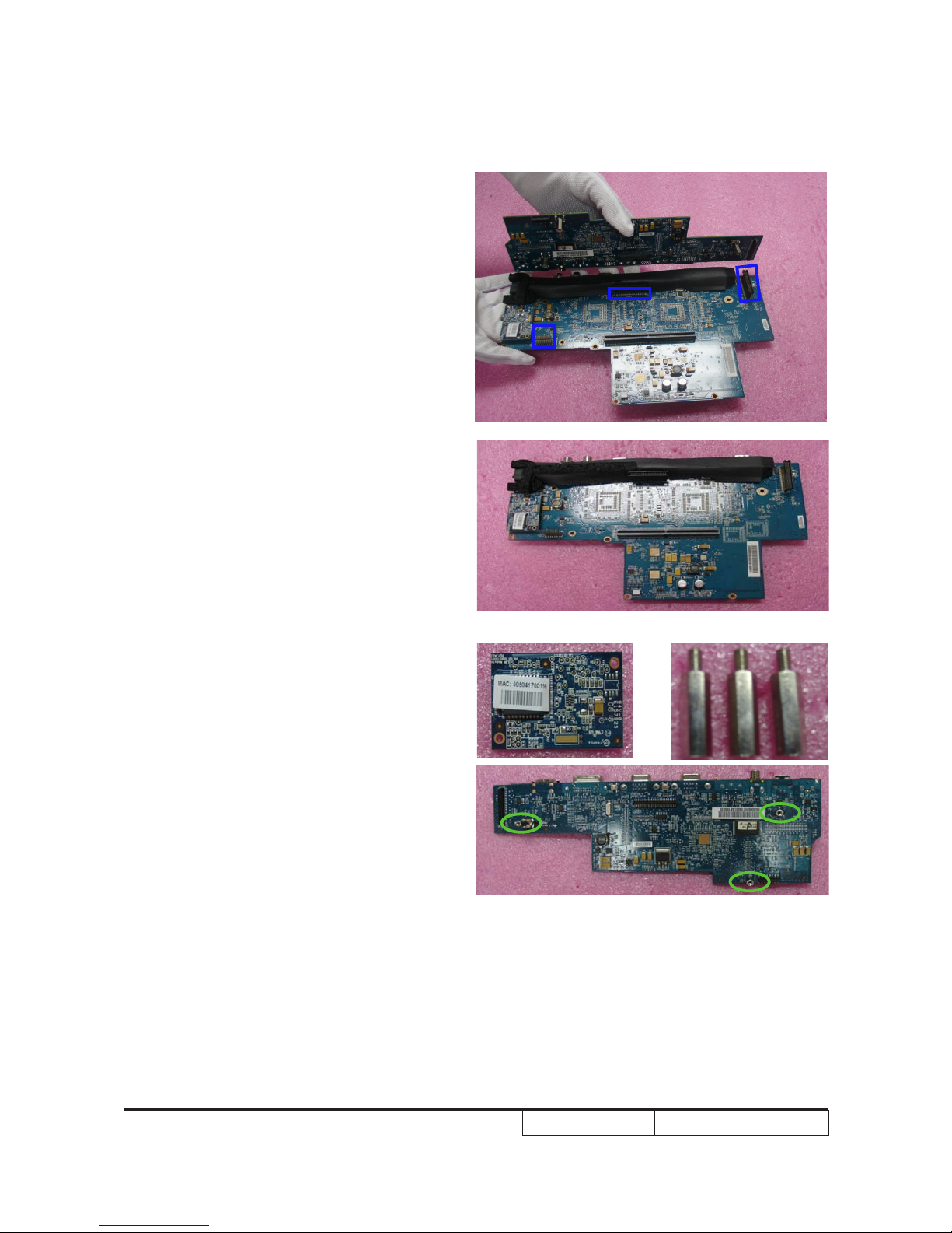
EP1080 Series Condential 2-9
5. Unplug 3 connectors (as blue square) to
seperate two boards.
6. Take off Lan Board from the Formatter
Board.
7. Take off 3 Hex screws (as green circle)
from the Scaler Board.
EP1080 Series Condential 2-10
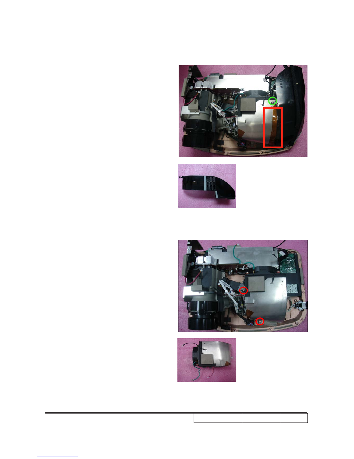
2-10 Disassemble Air Duct
1. Tear off 1 tape kapton (as red square).
2. Unscrew 1 screw (as green circle), then
disassemble Air Duct.
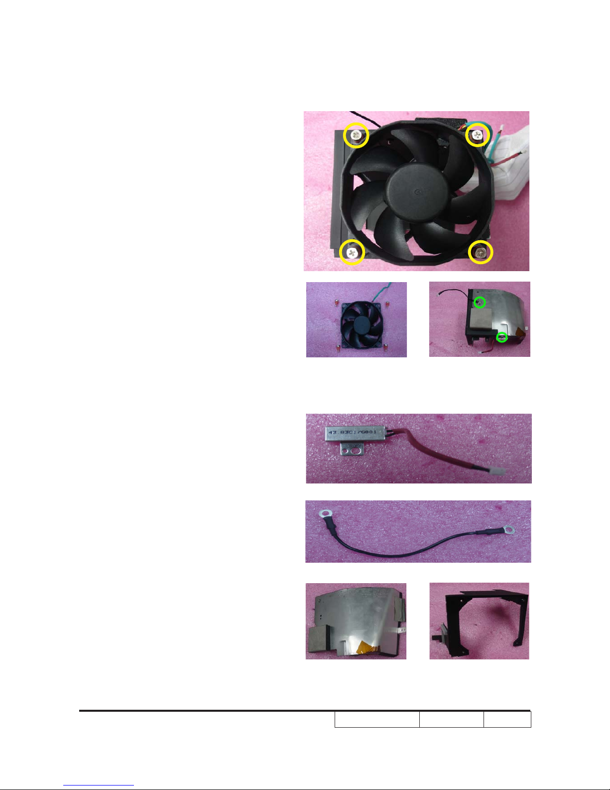
2-11 Disassemble System
Fan Module
1. Unscrew 2 screws (as red circle) and
disassemble Fan Module.
EP1080 Series Condential 2-11
2. Unscrew 4 screws (as yellow circle) and
separate Bracket and Fan.
3. Unscrew 2 screws (as green circle),
separate thermal switch and ground wire
and others.
EP1080 Series Condential 2-12
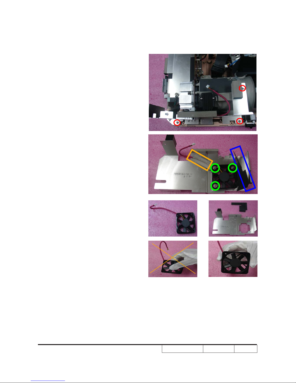
2-12 Disassemble Left
Shielding Module
1. Unscrew 3 screws (as red circle) and
disassemble Left Shielding Module.
2. Tear off mylar (as orange square),
unscrew 3 screws (as green circle) and
separate Fan and Left Shielding , then
tear off mylar (as blue square) from the
Left Shielding.
Note: - Take the Fan Module as the right
gesture.
the wrong gesture
the right gesture
EP1080 Series Condential 2-13
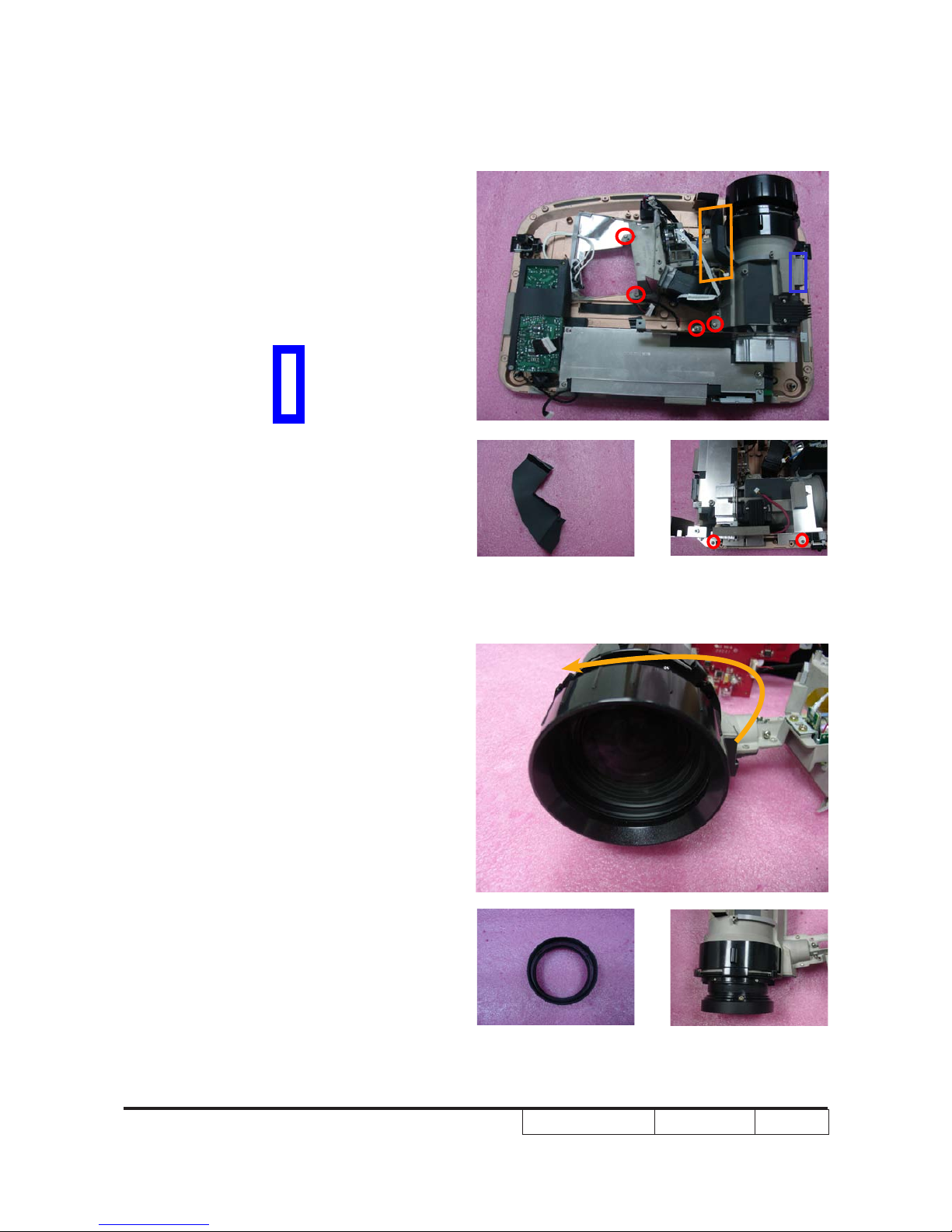
2-13 Disassemble Engine
Module
1. Disassemble 1 mylar (as orange square)
and EMI Gasket (as blue square).
2 .Unscrew 6 screws (as red circle) to
disassemble Engine Module.
3. Turn the Focus Ring as the yellow as the yellow
direction,then disassemble Focus Ring.disassemble Focus Ring.
EP1080 Series Condential 2-14
4. Unscrew 2 screws on the zoom ring
cover (as red circle),remove the Zoom
Ring as the picture.
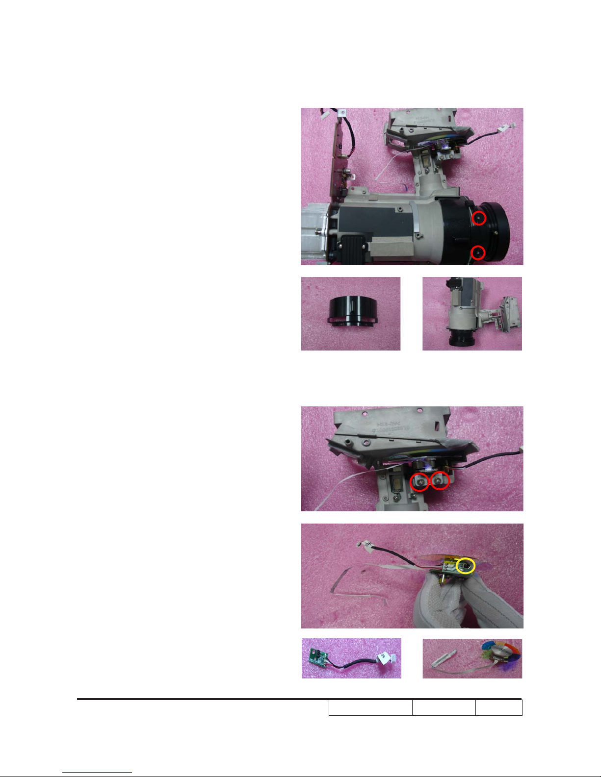
2-14 Disassemble Color
Wheel Module
1. Unscrew 2 screws (as red circle) to
disassemble Color Wheel Module.
2. Unscrew 1 screw (as yellow circle) to
disassemble Photo Sensor Board from
Color Wheel Module.
Note: - Avoid to touch the glass parts of color
wheel.
EP1080 Series Condential 2-15
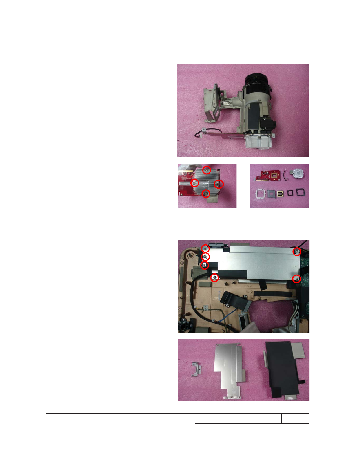
2-15 Disassemble DMD Chip
1. Unscrew 4 screws (as red circle) on the
heatsink bracket and separate all parts.
Note: - The manner of placing a DMD mask.
- Use an electrostatic ion gun to puff
the engine room in the DMD mask.
- If there are scrapes or dirt on the
DMD chip when using a magnifying
glass to have a close look, use an
electrostatic ion gun to clean it.
- To double check and see if the pin is
out of shape.
2-16 Disassemble LVPS
Module
1.Unscrew 6 screws (as red circle).
2. Disassemble LVPS Module holder, mylar,Disassemble LVPS Module holder, mylar,
AC Inlet Bracket.
EP1080 Series Condential 2-16
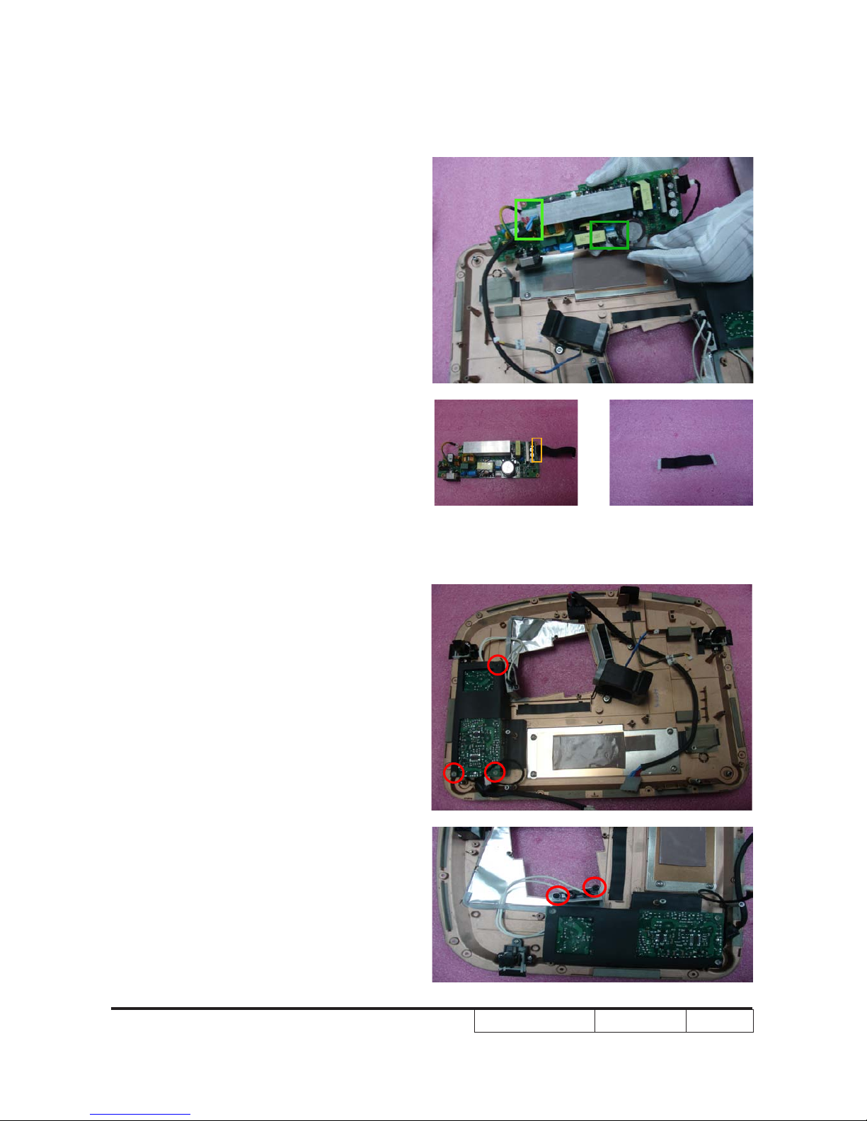
2-17 Disassemble Ballast
Module
1. Unsrew 5 srews (as red circle),and
disassemble Ballast Module.
3. Unplug 2 connectors (as green square).
4. Unplug 1 connector (as yellow square)(as yellow square)
and separate LVPS and the wire .and separate LVPS and the wire .
EP1080 Series Condential 2-17
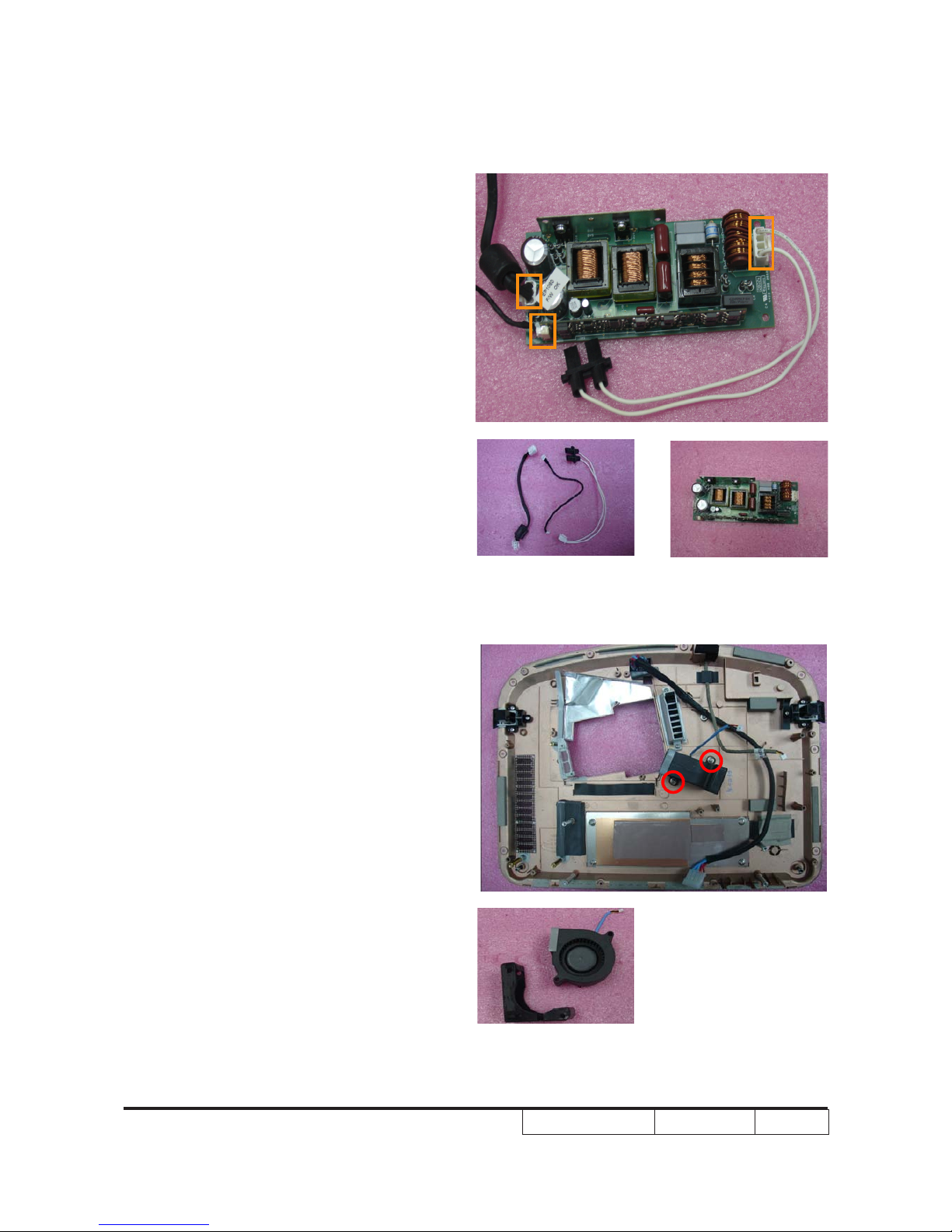
2-18 Disassemble Blower
Module
1. Unscrew 2 screws (as red circle).
2. Remove the Blower Module and
separate Blower and Rubber.
2. Unplug 3 connectors (as orange square)
and all wires,then dissassemble Ballast
Module.
 Loading...