

Page 1
SER VICE MANUAL
Model Name : PI500
Prepared by SI :
________________________________________
Prepared by TSE :
________________________________________
Check by :
________________________________________
Approved by :
________________________________________
etaDnoisreVesiveRnoitpircseD
6/2/40020.1VeussIlaitinI
Copyright February, 2004 . All Rights Reserved
Document #621-G04-01A . P/N: 36.62101.001
Page 2

Prefa ce
This ma nual is prepared for the maintena nce service f or the PI500 LCD
Panel Monitor. Maintenance procedures described in this manual are intended to isolate faulty parts
and replace them in the field. It also aims to serve as a guide in procuring replacement parts for this
product.
This manual is copyrighted and all rights are reserved. This product may not, in whole or in part be
copied, photocopied, translated or reduced to any electronic or ma chine readable form without prior
written consent except for copyies retained by the purchaser for backup purpose.
This manual includes major system asse mbly, and the “Troubleshooting” makes explanations on how
to detect errors. It also includes a flow chart for checking or correcting faults.
No Warranty or representation, either expressed or implied, is made with respect to this
documentation, its quality, performance, merchantability or fitness for particular purpose.
No event will the vendor be liable for direct, indirect, special, incidental or consequential damages
arising out of the user or inability to use this product or documentation.
Notice:
The information found in this manual is subject to cha nge without prior notice. Any subse-
quent changes made to the data herein will be incorporated in future edition.
PI500 Service Ma nual
Copyright February, 2004
All Rights Reserved
Ma nual V ersion 1.0
Document #621-G04-01A
PI500i
Page 3

Table of Contents
Chapter 1 Introduction 1-1
The Appropriate Operation 1-1
Product Highlight 1-5
Technical Specification 1-6
Compatible Modes 1-9
Chapter 2 Disassembly of Procedure 2-1
Removing Front Cover and Control Board 2-1
Removing Main Board 2-3
Removing Inverter Board and IF Card 2-4
Removing LCD Pa nel 2-5
Removing Audio Board, Sta nd a nd Re ar Cover 2-5
Chapter 3 Troubleshooting 3-1
Equipment Needed 3-1
Main Procedure 3-2
Chapter 4 Function Test and Alignment Procedure 4-1
Product 4-1
Test Equipment 4-1
Hot Key 4-1
Test Condition 4-2
Test Display Modes a nd Pattern 4-3
Function Test and Alignment Procedure 4-6
Clea ning 4-8
Chapter 5 Firmware Upgrade Procedure 5-1
Equipment Needed 5-1
Hardware Setup 5-2
Software Procedure 5-2
Chapter 6 DDC Key-in Procedure 6-1
Equipment Needed 6-1
Hardware Setup 6-2
Software Procedure 6-2
PI500ii
Page 4

Chapter 7 Touch Panel Driver Calibration Procedure 7-1
T ouch Function T est 7-1
Calibration 7-3
Appendix A 8-1
Exploded Overview 8-1
Appendix B 8- 3
Serial Number System Definition 8-3
Reader’s Response 8-5
PI500iii
Page 5

Chapter 1
Introduction
This manual provides an integral technical information you need to maintain the LCD Monitor.
And this manual is applied to the model of 1024 x 768 pixels color TFT LCD Monitor with a 15”
flat pa nel screen. There are six topics in this ma nual, a nd you can i mmediately identify problems through this
ma nual.
This manual is for the technicians and people who have the electronic background. Send the
product back to the distributor for re pairing and do not attempt to do anything which is complex or
not mentioned in the troubleshooting.
1-1 The Appropriate Operation
1-1.1 For Monitor
Turn off the product before cleaning.
Use only a dry soft cloth when cleaning the Touch panel surfa ce.
Use a soft cloth moistured with mild detergent to clean the display housing.
Use only high quality and safety approved AC/DC power adapter.
Disconnect the power plug from AC outlet if the product is not used for a long period of
time.
Do not touch the Touch panel surface with sharp or hard objects.
Do not use abrasive cleaners, waxes or solvents for your cleaning.
Do not operate the product under the following conditions :
- Extremely hot, cold or humid environment.
- Areas susceptible to excessive dusts and dirt.
- Near any appliance generating a strong magnetic field.
- Place in direct sunlight.
Coretronic Corporation
1-1
PI500
Page 6

1-1.2 LCD Module Handling Precautions
1) Since front polarizer is easily damaged, pay attention not to scratch it.
2) Be sure to turn off power supply when inserting or disconnecting from input connector.
3) Wi pe off water drop i mmediately . Long conta ct with water may cause discoloration or spots.
4) When the panel surface is soiled, wipe it with absorbent cotton or other soft cloth.
5) Since the panel is made of glass, it may break or crack if dropped or bumped on hard surface.
6) Since CMOS LSI is used in this module, take care of static electricity and insure human earth
when handling.
7) Do not open nor modify the Module Assembly .
8) Do not press the reflector sheet at the back of the module to any directions.
9) In case if a Module has to be put back into the packing container slot after once it was taken out
from the container, do not press the center of the CCFL Reflector edge. Instead, press at the far
ends of the CFL Reflector edge softly. Otherwise the TFT Module may be damaged.
10) At the insertion or removal of the Signal Interface Connector, be sure not to rotate nor tilt the
Interface Connector of the TFT Module.
11) After installation of the TFT Module into an enclosure (LCD monitor housing, for example), do not
twist nor bend the TFT Module even momentary . At designing the enclosure, it should be taken
into consideration that no bending/twisting forces are applied to the TFT Module from outside.
Otherwise the TFT Module may be damaged.
12) Cold cathode fluorescent lamp in LCD contains a small amount of mercury. Please follow local
ordinances or regulations for disposal.
13) Small amount of materials having no flammability grade is used in the LCD module.
The LCD module should be supplied by power complied with requirements of Limited Power Source
(IEC60950 or UL1950), or be applied exemption.
14) The LCD module is designed so that the CFL in it is supplied by Limited Current
Circuit(IEC60950 or UL1950). Do not connect the CFL in Hazardous Voltage Circuit.
Coretronic Corporation
1-2
PI500
Page 7
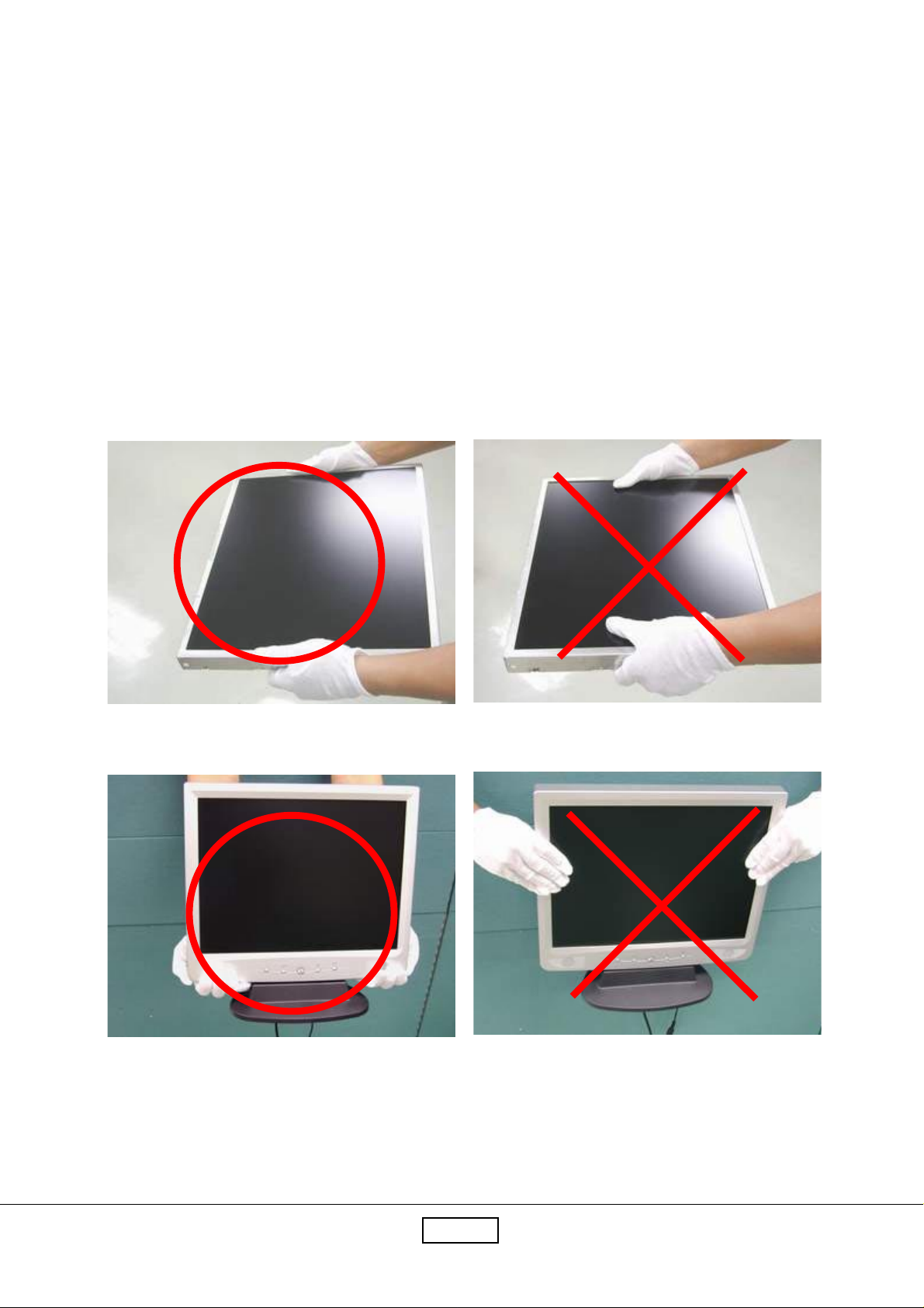
1-1.3 Handling and Placing Methods
Correct Methods:
Only touch the metal frame of the
LCD panel or the front cover of the
monitor . Do not touch the surfa ce of
the polarizer.
Incorrect Methods:
Surface of the LCD pa nel is pressed
by fingers a nd that will probably
cause “Mura.”
Coretronic Corporation
1-3
PI500
Page 8
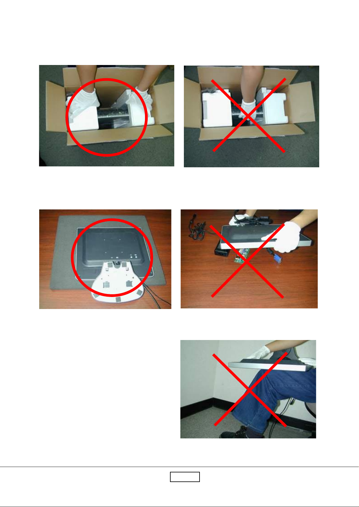
T ake out the monitor with cushions
T aking out the monitor by grasping the LCD
pa nel. That will probably cause “Mura.”
Place the monitor on a clean a nd soft foa m pad.
Placing the monitor on f oreign objects. That will
probably scratch the surfa ce of the pa nel or cause
“Mura.”
Coretronic Corporation
The pa nel is placed fa cedown on the lap. That
will probably cause “Mura.”
1-4
PI500
Page 9

1-2 Product Highlight
15" XGA TFT Color LCD Touch Monitor
Analog signal input
Active matrix TFT LCD technology
1024 x 768 a ddressa ble pixels
250 cd/m2 brightness
31.5-60 kHz horizontal sca n
56-75Hz high refresh rate
Auto-a djustment
Multifunction OSD user controls
VESA DPMS power saving
Power on lock function
Kensington lock function
Pen Input Screen
Coretronic Corporation
1-5
PI500
Page 10

1-3 Technical Specification
LCD Pa nel -Active matrix TFT color LCD.
-15.0" diagonal screen size
-1024 x 768 a ddressable pixels
-0.297 mm x 0.297 mm pixel pitch
-250 cd/m2(typ.) brightness
-400 : 1 (typ.) contrast ratio
-U/D : 40/60 (Typ.),L/R : 60/60 ,CR=10
-Tr + Tf : 16 ms (typ)
-Lamp number : 2 CCFLs
-Life : 30,000 hrs (T yp.)
T a blet -Electromagnetic
-Interface : USB
-Resolution : 500 lpi
-Accuracy : +/-0.5mm
-Pressure level : 512 levels
-Report Rate : 125 reports/per second
-Maxi mum Reading Height : 25mm a bove the pa nel or protection object
-Maxi mum Writing He ight : 20mm above the pa nel or protection object
-Operating System : W in98/2000,ME,XP,MAC 9.0/9.1/9.2
Display Resolution -1024 pixels (H) x 768 lines(V)
Active Display Area -304.1(H) x 228.1(V)mm
Display Color -262144 colors (6-bits color)
Horizontal Sca n -31.5kHz to 60kHz
Vertical Refresh -56Hz to 75Hz
Pixel Frequency -78.75MHz
Coretronic Corporation
1-6
PI500
Page 11

Pen Input Screen -AIPTEK T ablet
Compatibility -IBM & VESA VGA 640 x 350,70Hz
640 x 400,70Hz
720 x 400,70Hz
640 x 480,60Hz
640 x 480,72/75Hz
-VESA SVGA 800 x 600,56/60/72/75Hz
-VESA XGA 1024 x 768,60/70/75Hz
-Apple Ma c LC 640 x 480,67Hz
-Apple Ma c II 640 x 480,67Hz
-Apple M a c 832 x 624,75Hz
1024 x 768,75Hz
Input Signal -PC T ype
Analog Computer input
V ideo: analog R GB 0.7V p-p
Sync. : separate sync.
Auto-adjustment -Y e s
I/O Connectors -DC power in (Pig tail)
-V GA f or Analog computer input (Pig tail)
Power Saving -VESA DPMS sta ndard
Power Consumption -30watt (max.), < 3watt (off mode)
Coretronic Corporation
1-7
PI500
Page 12

Environmental -T e mperature : Operating temperature : 5°C ~ 35°C
Non-Operating temperature : -20°C ~ 60°C
-Humidity :
Operating : 80% maximum
Non-Operating : 80% maxim um
Mounting interface -VESA Flat Pa nel Monitor Physical Mounting Interfa ce
(75 mm x 75 mm)
AC/AD Adapter -External power ada pter
-Universal type AC 100-240V(50/60Hz)
-Output :DC12V
-UL , CSA , TUV , CE , CE Mark compli ant
Agency approval -FCC-B, CE-B, VCCI-II , UL, CUL, TUV,
Sta ndard Package -the PI-500 contains the followings :
LCD monitor with stand
Power cord
AC/DC Adapter
User’s ma nual
SoftW are *3
Pen
Pen house
Figure of pen tweezers
Battery *1
Coretronic Corporation
1-8
PI500
Page 13

1-4 Compatible Modes
Standard Resolution Vertical Refresh Horizontal Scan
(Hz) (KHz)
IBM VGA 640 x 350 70 31.5
IBM VGA 640 x 400 70 31.5
IBM VGA 720 x 400 70 31.5
IBM VGA 640 x 480 60 31.5
VESA VGA 640 x 480 72 37.9
VESA VGA 640 x 480 75 37.5
VESA SVGA 800 x 600 56 35.2
VESA SVGA 800 x 600 60 37.9
VESA SVGA 800 x 600 72 48.1
VESA SVGA 800 x 600 75 46.9
VESA XGA 1024 x 768 60 48.4
VESA XGA 1024 x 768 70 56.5
VESA XGA 1024 x 768 75 60.0
Apple Mac LC 640 x 480 67 34.9
Apple Mac II 640 x 480 67 35.0
Apple Mac 832 x 624 75 49.7
Apple Mac 1024 x 768 75 60.2
Coretronic Corporation
1-9
PI500
Page 14
Chapter 2
Disasse mbly Procedure
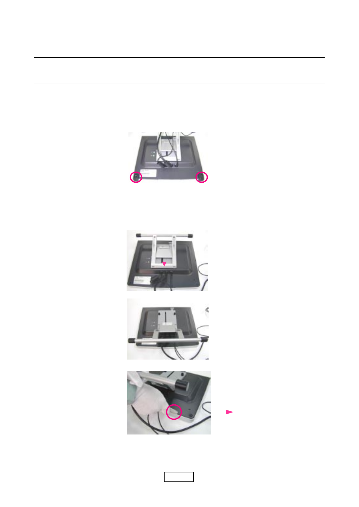
2-1 Removing Front Cover and Control Board
1. Lay PI500 fa cedown a nd unscrew 2 screws to re move the rubber feet.
2. Push the sta nd ba ck a nd use the pla stic plate to separate the front cover from the main body.
Plastic Plate
2-1Coretronic Corporation
PI500
Page 15
3. Unscrew 4 screws to lift up the pa nel module.
4. Lift up the pa nel module, a nd unplug 2 ca bles to remove the front cover .
Front Cover
5. Unscrew 4 screws to remove the speakers.
6. Unscrew 3 screws to remove the control board.
Control Board
PI5002-2Coretronic Corporation
Page 16

2-2 Removing Main Board
7. Lift up the pa nel module a nd unplug 4 ca bles to deta ch the pa nel module from the rear cover .
8. Disconnect 3 ca bles to remove the main board a nd unscrew 4 screws (a s red circles show).
Main Board
2-3Coretronic Corporation
PI500
Page 17

2-3 Removing Inverter Board & IF Card
8. Unscrew 2 screws (a s yellow circles show) a nd unplug 3 ca bles (a s red circles indicate) to
remove the inverter board.
Inverter Board
9. Unscrew 3 screws to re move the shielding plate a nd then unscrew 2 screws, a nd unplug 2
cables to re move the IF card.
IF card
PI5002-4Coretronic Corporation
Page 18

2-4 Removing LCD Panel
9. Use a knife to separate the protection glass from the LCD panel at four conners.
Notice:
1.) While using the knife, be careful not to scratch the LCD Panel.
2.) The double tapes can not be reused after being cut off.
Protection Glass
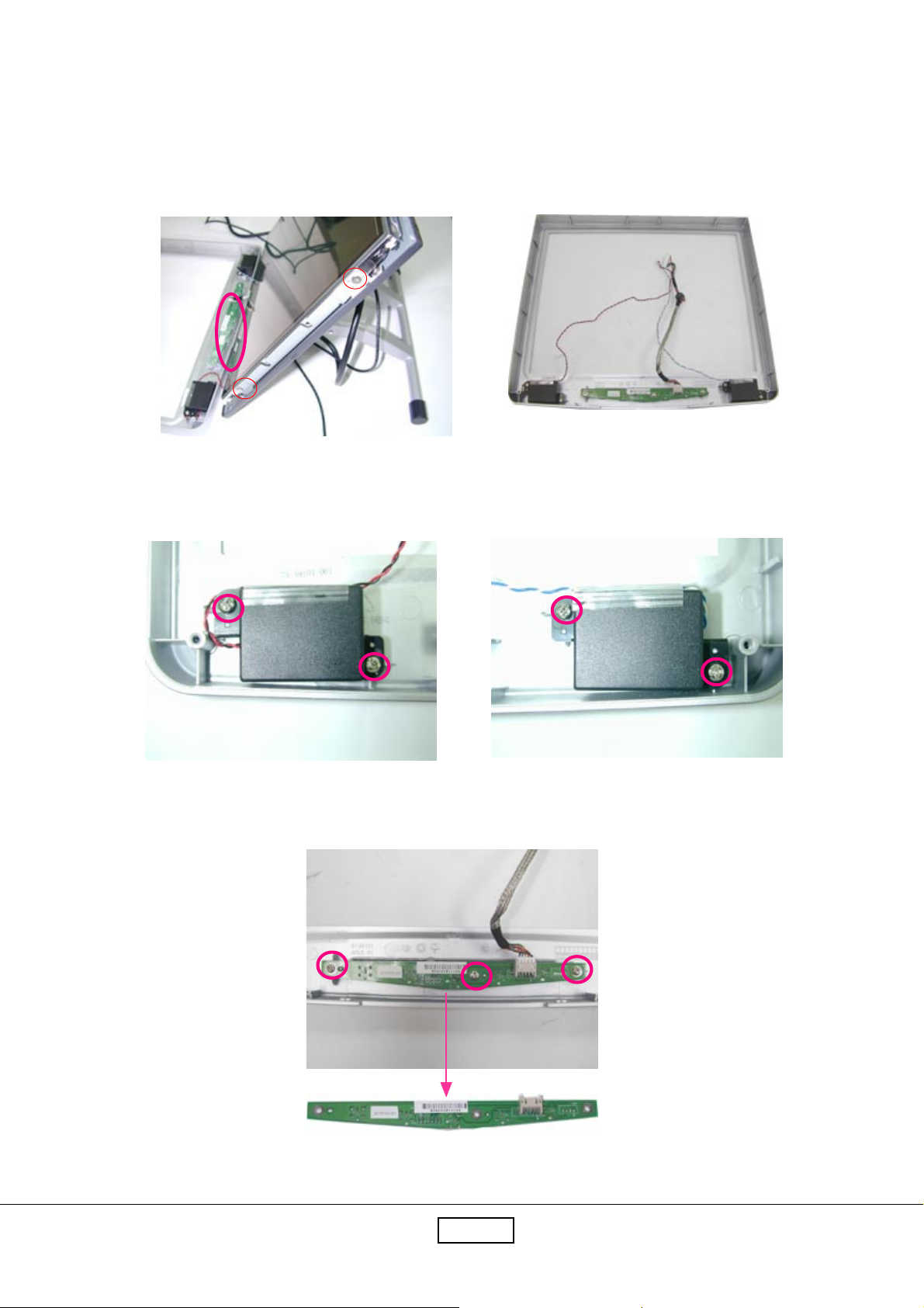
2-5 Removing Audio Board, Stand & Rear Cover
10. Unscrew 2 screws a nd unplug a wire to remove the audio board.
LCD Panel
Audio Board
2-5Coretronic Corporation
PI500
Page 19

11. Use the nipper to re move 3 lockers a nd unscrew one screw, then you ca n remove the 3 wires.
12. Unscrew 4 screws to separate the stand from the rear cover and then unscrew 5 screws to
disassemble the sta nd.
13. Unscrew 4 screws to remove the holders.
PI5002-6Coretronic Corporation
Page 20

Chapter 3
Trouble shooting
3-1 Equipment Needed
- PI500 Monitor
- Philips Screw Driver #101 a nd #107
- PC(Personal Computer) with XGA resolution.
- Sound Card.
- 8% ND Filter
- T ouch Test T ooling (Arcylic)
PI5003-1
Page 21

3-2 Main Procedure
Start
Power-on
Power LED ok ?
Yes
Is display
performance ok ?
Yes
Is function
adjustment ok ?
Yes
Are Speakers all
right?
Yes
No
No
No
No
A. Power Circuit
Troubleshooting
B. Performa nce
Troubleshooting
C. Function
Troubleshooting
D. Speakers
Troubleshooting
T ouch Function
OK?
Yes
End
No
E. Touch Function
Troubleshooting
PI5003-2
Page 22

3-2.1 A. Power Circuit Troubleshooting
Start
Change
AC/DC
Adapter
Yes
End
No
Change
Main Board
3-2.2 B. Performance Troubleshooting
Start
Change
Is screen black ?
Yes
Inverter Board
No
Change
Main Board
Yes
No
Change
LCD Panel
No
Is screen white ?
No
Abnormal Color ?
No
1
Yes
Replug/Change
FPC Cable
Yes
Change
Main Board
Yes
Yes
Yes
No
No
Yes
Change
Main Board
Yes
Change
LCD Panel
Yes
No
Yes
Change
LCD Panel
Yes
PI5003-3
Page 23

1
Is LCD line defective
?
No
Mura?
No
Is screen scrolling ?
No
Is screen flickering ?
Yes
Yes
Yes
Yes
Change
LCD Panel
Yes
Change
LCD Panel
Yes
Change
Main Board
Yes
Change
Main Board
No
Change
LCD Panel
No
Bad Uniformity ?
No
Have line bar or
noise?
No
Ghost image ?
No
Yes
Yes
Yes
Yes
Change
Inverter Board
Yes
Adjust
“Frequency” or
“Auto Adjustment”
Yes
Refer
to
Notice
No
1
Yes
No
Change
LCD Panel
No
Change
Main Board
Adjust
“Frequency” or
“Auto Adjustment”
Yes
Yes
Yes
No
Yes
Refer
to
Notice
2
Yes
No
Change
Main Board
Yes
End
PI5003-4
Page 24

Notice 1 Make sure VGA cable connect to PC directly don’t via anything like “Data transfer” or
“Distribution”......After this action if Ghost i mage disappear , go to “Yes”; else, go to “No”.
Notice 2 Check the compatibility on the computer. If it is compatibility problem, feedback the
information to Coretronic; else, go to “No”.
3-2.3 C. Contorl Function Troubleshooting
Start
Change
Control Board
Yes
End
No
Change
Main Board
Yes
3-2.4 D. Speakers Troubleshooting
Start
Change
Speakers
No
Change
Audio Board
End
Yes
Yes
PI5003-5
Page 25

3-2.5 E. Touch Function Troubleshooting
Start
Change
T ouch Pen
Yes
End
Note: The Voltage of battery of T ouch Pen must be higher tha n 1.2V.
No
Change
IF Card
Yes
No
Change
LCD Panel
Yes
PI5003-6
Page 26

Chapter 4
Function Test & Align ment Procedure
4-1 Product
- PI500
4-2 Test Equipment
- Color V ideo Signal & Pattern Generator (or PC with XGA resolution)
- 8% ND Filter
- Touch Test Tooling (Arcylic)
4-3 Hot Key
- Service Mode :
Depress “Menu” and Power ON
- White Balance :
Press “Menu” , “-” a nd “Power” buttons si multa neously .
- All Mode Reset :
Press “+”, “-” buttons simulta neously and “Power on” with signal,
hold on for 3 seconds. Then the screen will show “All Mode Reset”.
- Burn In Mode :
Press “+”, “-” buttons simulta neously a nd “Power on” without signal,
hold on for 3 seconds. Then the screen will show “Burn In Mode”.
Press a ny button beside s “Power” button, you ca n find the information
about this monitor .
PI5004-1
Page 27

4-4 Test Condition
Before function test a nd alignment, ea ch LCD Monitor should be run-in
a nd warmed-up for at lea st 2 hours with the following conditions:
a). In room temperature
b). W ith full-white screen, R.G.B. Black
c). With cycled display modes
640*480 (H=37.5kHz, V=75Hz)
800*600 (H=46.9kHz, V=75Hz)
1024*768 (H=60.0kHz, V=75Hz)
PI5004-2
Page 28

4-5 Test Display Modes & Pattern
4-5.1 Compatible Modes
Sta ndard Resolution Vertical Refresh Horizontal Scan
(Hz) (KHz)
IBM VGA 640 x 350 70 31.5
IBM VGA 640 x 400 70 31.5
IBM VGA 720 x 400 70 31.5
IBM VGA 640 x 480 60 31.5
VESA VGA 640 x 480 72 37.9
VESA VGA 640 x 480 75 37.5
VESA SV G A 800 x 600 56 35.2
VESA SVGA 800 x 600 60 37.9
VESA SVGA 800 x 600 72 48.1
VESA SVGA 800 x 600 75 46.9
VESA XGA 1024 x 768 60 48.4
VESA XGA 1024 x 768 70 56.5
VESA XGA 1024 x 768 75 60.0
Apple Ma c LC 640 x 480 67 34.9
Apple M a c II 640 x 480 67 35.0
Apple Mac 832 x 624 75 49.7
Apple Mac 1024 x 768 75 60.2
PI5004-3
Page 29

4-5.2 Function Test Display Pattern
metI tnetnoCtseT nrettaP noitacificepS krameR
1gnikcarT&ycneuqerFerioMeniLeniF.esionyvawlausivetanimilE1erugiF
2ssenthgirB/tsartnoCelacSyarG61.elbahsiugnitsidebdluohsslevelyarg612erugiF
3yradnuoB
4
5
6eniL/lexiPdaeD
7ecnalaBetihW
lacitreV&latnoziroH
ssenkcihT
roloC,B,G,R
ecnamrofreP
&ytimrofinUneercS
rekcilF
roloCB.G.R
seitisnetnI
etihWlluF.cepsehthtiwtnailpmocebdluohS7erugiF
neercSetihW
neercSkraD
kcalB&etihW
nrettaP
.emarf
.lamroneb
.cepsehthtiwtnailpmoc
dluhsoedivfonoitisop.treVdna.zroH
neercsehtnihtiwebotelbatsujdaeb
dluohsroloc,B,G,RhcaefotsartnoC
ebdluohsslexipdaedfosrebmunehT
etihwerupehtevahtsumneercsehT
.rolocrehtoon,nrettapkcalbdna
3erugiF
6,5,4erugiF
8,7erugiF
9,2erugiF
Fine Line Morie Pattern (Figure 1) Gray Scale Pattern (Figure 2)
Horizontal & Vertical Thickness Pattern (Figure 3) R. Color Pattern (Figure 4)
PI5004-4
Page 30

G. Color Pattern (Figure 5) B. Color Pattern (Figure 6)
Full White Pattern (Figure 7) Dark Screen Pattern (Figure 8)
Black-White Pattern (Figure 9)
PI5004-5
Page 31

4-6 Function Test and Alignment Procedure
4-6.1 All Modes Reset
Y ou should do “All Mode Reset” first. This action will allow you to erase all end-user’s
settings a nd restore the factory defaults.
4-6.2 Auto-Adjustment
Please select a nd enter “Auto Adjustment” function on M ain Menu or press “Auto” button
on the select knob to see if it is workable. The “Auto Adjustment” function is ai med to offer
a better screen quality by built-in Scaler. For opti mum screen quality , the user ha s to a djust
each function ma nually.
4-6.3 Firmware
T est Pattern : Burn In Mode
- M ake sure the F/W is the latest version.
4-6.4 DDC
T est Program : EDID Program
- M ake sure the S/N is the sa me a s the Spec. la bel.
- Make sure the model na me is correct.
4-6.5 Frequency and Tracking
T est Signal: 1024*768@75Hz
T est Pattern: Line Moire Pattern
- Check a nd see if the i mage has noise a nd focus perf orms well.
eliminate visual line bar .
- If not, rea djust by the following steps :
(a) Select a nd enter “Frequency” function to a djust the image
to eliminate visual line bar .
(b) Select a nd enter “T racking” function to a djust the i mage
to eliminate visual wavy noise.
PI5004-6
Page 32

4-6.6 Boundary
T est Signal : 1024*768@75Hz
T est Pattern : Horizontal & V ertical Line Thickness Pattern.
- Check a nd see if the i mage boundary is within the screen frame.
- If not, select “Horizontal Position” a nd “V ertical Position” function
to a djust the video boundary to be full sca nned a nd within screen frame.
4-6.7 White Balance
T est Signal : 1024*768@75Hz
T est Pattern: Bla ck -White Pattern & 16-Gray-Scale Pattern.
- Set up PC at Bla ck-White Pattern, a nd then
press “Menu” , “-” a nd “Power” buttons simulta neously .
- Use 16-Gray-Scale Pattern to check the performance.
The 16-Scale must be distinguishable.
4-6.8 R,G,B, Colors Contrast
T est Signal: 1024*768@75Hz
T est Pattern: R,G,B Color Intensities Pattern a nd 16 Gray Scale Pattern.
- Check a nd see if each color is normal a nd distinguisha ble.
4-6.9 Screen Uniformity and Flicker
T est Signal: 1024*768@75Hz
Test Pattern: Full White Pattern
- Check and see if it is in normal condition.
4-6.10 Dead Pixel and Line
T est Signal: 1024*768@75Hz
Test Pattern: Dark and White Screen Pattern
- Check a nd see if there are dea d pixels on LCD pa nel with shadow gauge a nd filter film.
- The total numbers a nd distance of dea d pixels should be compliant with the spec.
- Line defect is una ccepta ble.
PI5004-7
Page 33

4-6.11 Check for Secondary Display Modes
T est Signal: 640*480@60/72/75Hz; 720*400@70Hz;
800*600@60/72/75Hz
- Normally when the pri mary mode 1024*768@75Hz is well a djusted a nd
complia nt with the specification, the secondary display mode s will be great possibile to be
compliant with the spec. But we still have to check with the general test pattern to make
sure every secondary is complia nt with the specification.
4-6.12 Mura
T est Pattern:Full White Pattern
- M ake sure there is no “Mura” appears on the screen.
4-6.13 Audio
Test Signal:Music
- M ake sure left a nd right speakers are OK both.
- When plug-in earphone, the internal speaker will be disable.
- Check “Mute” function, it should be no sound when “Mute” function is enable.
4-6.14 Touch Panel
Please refer to Cha pter 7.
4-6.15 Cosmetic
For Like New units:
- The spec. must be compliants to “Like-New Spec.”.
For RMA units:
- Don’t care about the scratche s. (The scratches must be hight light while receive it.)
4-6.16 All Modes Reset
After final QC step, we have to erase all saved changes again a nd restore the fa ctory
defaults. You should do “All Mode Reset” again.
4-7 Clea ning
Please use non-alcohol cleanser to clean LCD panel and cosmetics
material with soft cotton.
PI5004-8
Page 34

Chapter 5
Firmware Upgrade Procedure
5-1 Equipment Needed
1. PC
2. Flash Board
3. RS232 Cable
4. VGA Cable
5. Power Adapter
6. An a dditional monitor
COM1: to
RS232 Cable
VGA Port
Flash Board (V3)
P1: To RS-232 Cable
P2 : To VGA Cable
JP1: to Power Adapter
JP4 Close
JP3 Open
PC
Coretronic Corporation
RS-232 Cable (P/N:42.55907.001)
VGA Cable (P/N:42.56109.001)Power Adapter (P/N:47.56001.501)
5-1
PI500
Page 35

5-2 Hardware Setup
1. JP3 of Flash Board must be open a nd JP4 must be closed (short).
2 .Link VGA port of Fla sh Board and V GA port of PI500 with V GA Ca ble.
3 .Link COM1 of PC and P1 of Fla sh Board with RS232 Ca ble.
4. Plug Power Ada pter into Flash Board.
5. Hold “Menu” button of PI500, a nd then plug Power Adapter into PI500.
6. Link V GA port of PC a nd V G A port of the a dditional monitor with V GA Cable.
5-3 Software Procedure
Step1. Execute “Upgrader.exe”
Coretronic Corporation
5-2
PI500
Page 36

Step2. Click “Open File” button.
Step 3. Select Firmware file, a nd then click “OK” button.
Coretronic Corporation
5-3
PI500
Page 37

Step 4. Click “Initial” button, a nd then click “OK”.
*Note 1
Step5. Click “Program” button, a nd then waiting for “Downloa d OK!!” message.
Coretronic Corporation
5-4
PI500
Page 38

Step 6. Unplug Power Ada pter of PI500 a nd then re-plug in again.
Note 1: If the message is “Loader Error!!”
1. Click “OK.”
2. Click “Reset” button.
3. Check hardware settings a nd then go to Step 4.
Coretronic Corporation
5-5
PI500
Page 39

Chapter 6
DDC Key in Procedure
6-1 Equipment Needed
1. PC
2. Flash Board (V3)
3. RS232 Cable
4. VG A Ca ble
5. Power Adapter
6. An a dditional monitor
COM1: to
RS232 Cable
VGA Port
PC
P1: Connected to
COM1 of PC
V3
P2: Connected to VGA Port of PI500
RS-232 Cable (P/N:42.55907.001)
JP1: Connected to
Power Adapter
JP3 close
JP4 open
Coretronic Corporation
6-1
VGA Cable (P/N:42.56109.001)Power Adapter (P/N:47.56001.501)
PI500
Page 40

6-2 Hardware Setup
1. Flash board’s JP3 must be closed (short) and JP4 must be open.
2. Link COM1 of PC and P1 of Flash board with RS232 cable.
3. Link VGA port of PC and to the additional monitor with VGA cable.
4. Link P2 of Flash board a nd V GA port of PI500 with V GA ca ble.
5. Plug Power Adapter into Flash Board.
6. Plug Power Ada pter into PI500, but do not turn it on.
6-3 Software Procedure
Step1. Execute EDID progra m (PI500.exe).
Coretronic Corporation
6-2
PI500
Page 41

Step2. Key in Serial Number a nd then press ENTER button.
Step 3. It will a ppear message “V GA Suc.”
Step 4. Press “Shift” and “~” button on the keyboard. It will a ppear message
“CheckSum OK!” a nd Serial Number .
Coretronic Corporation
6-3
PI500
Page 42

Chapter 7
Touch Function Te st and Calibration
7-1 Touch Function Test
1. Equipment
- PC*2 : USB Port
Touch Driver
QC (p)99.exe
- Touch Pen
- Test T ooling (Acrylic)
2. Notice
- Don’t install a nother USB-Touch-Driver into the computer .
- The Battery Voltage of T ouch Pen must be higher tha n 1.2V.
- Y ou must prepare two PC, one is f or test “QC (p)99.exe”, a nother one is f or calibration.
- If you cha nge a T ouch Pen in testing precess, you must re-plug in USB port.
- The resolution must be set to 1024*768@75Hz.
Coretronic Corporation
7-1
PI500
Page 43

3. Test Procedure
- Execute “ QC (p)99.exe ”. (And then it will be “ White screen ” )
- Click “ right ” button of Mouse.
- Select “ T a blet T esting Mode ”, and then select “ Start ” to test.
(Afer click “ Start ”, “ ODM Code ” a nd “ Model Code ” message will show on
the screen. If the messages are not “ ODM Code ” a nd “ Model Code ”, the touch
function is something wrong.)
- Let T ouch Pen in active area.
- Slide T ouch Pen across Red-Square, Left-up, Right-down, in sequence.
- Use T ouch Pen to click Blue-Square, Left-up, Right-up, Left-down, Right-down,
in sequence.
- Use Arcylic T est T ooling to do draw test in sequence.
Coretronic Corporation
7-2
PI500
Page 44

7-2 Calibration
Step1. Click “USB T ablet” icon.
Step2. Click “Calibration” icon.
Coretronic Corporation
7-3
PI500
Page 45

Step2. Click “+” icon.
Coretronic Corporation
7-4
PI500
Page 46

Appendix A
Exploded Overview
I. PI500
Coretronic Corporation
8-1
DP.62101.01A
PI500
Page 47

Exploded Parts List
Coretronic Corporation
8-2
PI500
Page 48

Appendix B
I. Serial Number System Definition
Serial Number for LCD Display
A BBB Y WW C D BEML SSSS
1 2 3
: A = Coretronic, B~Z = OEM
1
: Product Code (ex: 621=
2
: Y = Last Number of the Year (ex: 200
3
: Week of Year
4
: Panel Vendor Code
5
: Electrical Classification (1=110V, 2=220V, 0=Universal)
6
: B = BIOS Version, E = PCB Board Version,
7
M = Mechanical Version, L = Location of Manufacture
8
: Serial Code (from 0001~)
4 5
6 7
PI500 Series)
2 - 2, 2003 - 3)
8
EX: A621338A0511K0043
This label “A621338A0511K0043” represents whole serial number
for PI500 including the first version of BIOS and Main Board. It’s
produced on the 38th week of 2003 for universal area and its serial code is 0043
and use AU panel.
Coretronic Corporation
8-3
PI500
Page 49

Serial Number for PCBA Main Board
M VV B Y X B1 SSSS
1
1
2
3
4
5
6
7
EX: HJ4M33A10001
2 3 4
5
: M = Vendor (ex: M = Might)
: VV = Model Code (ex:J4 =
: B = Main Board (ex: M= Main Board)
: Y = Last Number of the Year (ex: 200
: X = Month (ex: Jan. ~ Sept.=1~9, Oct.~Dec.=X, Y, Z)
: B1 = V ersion (ex: A1, A2...B1.....etc.)
: SSSS = Serial Code (from 0001~)
This label “MN8M36A10005” represents Main board of version
6
7
PI500 series...etc.)
1 - 1, 2002 - 2)
A1 for PI500 in March, 2003. Its serial code is 0001.
Coretronic Corporation
8-4
PI500
Page 50

*Reader’s Response*
Dear Readers:
Thank you for your backing our service manual up. In order to refine our content of
the service manual and satisfy your requirement. We expect you can offer us some precious opinions for reference.
Assessment:
A. What do you think about the content after reading PI500 Service Manual?
tinU tnellecxE dooG riaF daB
noitcudortnI.1
erudecorPylbmessasiD.2
gnitoohselbuorT.3
erudecorPtnemngilA&tseTnoitcnuF.4
erudecorPedargpUerawmriF.5
erudecorPni-yekCDD.6
noitarbilaCdnanoitallatsnIrevirDlenaPhcuoT.7
xidneppA.8
B. Are you satisfied with the PT150MU service manual?
metI tnellecxE dooG riaF daB
tnetnoClaunaMecivreS.1
tuoyaLlaunaMecivreS.2
gnitsildnamrofehT.3
C. Do you have any other opinion or suggestion about this service manual?
Reader’s basic data:
:emaN:eltiT
:ynapmoC
:ddA
:leT:xaF
:liam-E
After your finishing this form, please send it back to Coretronic Customer Service
Dept. by fax: 886-3-563-5333 or E-mail to service_lmt@coretronic.com Thanks :)
Coretronic Corporation
8-5
PI500
 Loading...