

Page 1
Universal projector
Projector
ush ceiling mount
Flush Mount
User manual
Optoma www.optoma.com
Model: OCM818W-RU / OCM818B-RU
www.optoma.com
Revision 24/01/2014Patent Pending
1
Page 2
IMPORTANT NOTES
● Thank you for purchasing the Projector Flush Mount. This bracket is suitable for most projectors up
to a load of 15kg.
● To ensure correct usage, please read this instruction manual thoroughly. Keep this manual for future
reference.
● Brackets should be mounted only be a qualified installer
● User will be responsible for any injuries and damages that may arise from improper installation and
handing of Projector Flush Mounting Kit.
● Ensure all mounting screws are appropriately positioned and properly tighten/ fastened.
● Installers are to ensure customer’s safety during installation.
● We reserve the right to amend or undertake any necessary changes without prior notice.
● Ensure the Ceiling can support the total weight of the Projector and the Projector Flush Mount.
● All bolts and screws must be used at the designated points as per installation instructions to prevent
damage to the projector unit, or injury.
● DO NOT install near an air conditioner or where there is excessive dust and smoke.
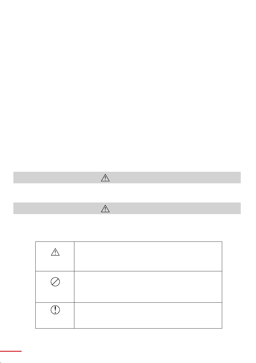
WARNING
This symbol indicates incorrect handling. Ignoring this symbol can result in the possibility of personal
injury or even death.
CAUTION
This symbol indicates incorrect handling. Ignoring this symbol can result in the possibility of personal
injury and physical damage.
Caution
(general)
Forbidden
(general)
Required
(general)
1
This symbol indicates additional cautions (including warnings).
This symbol indicates forbidden actions.
This symbol indicates required actions.
Page 3
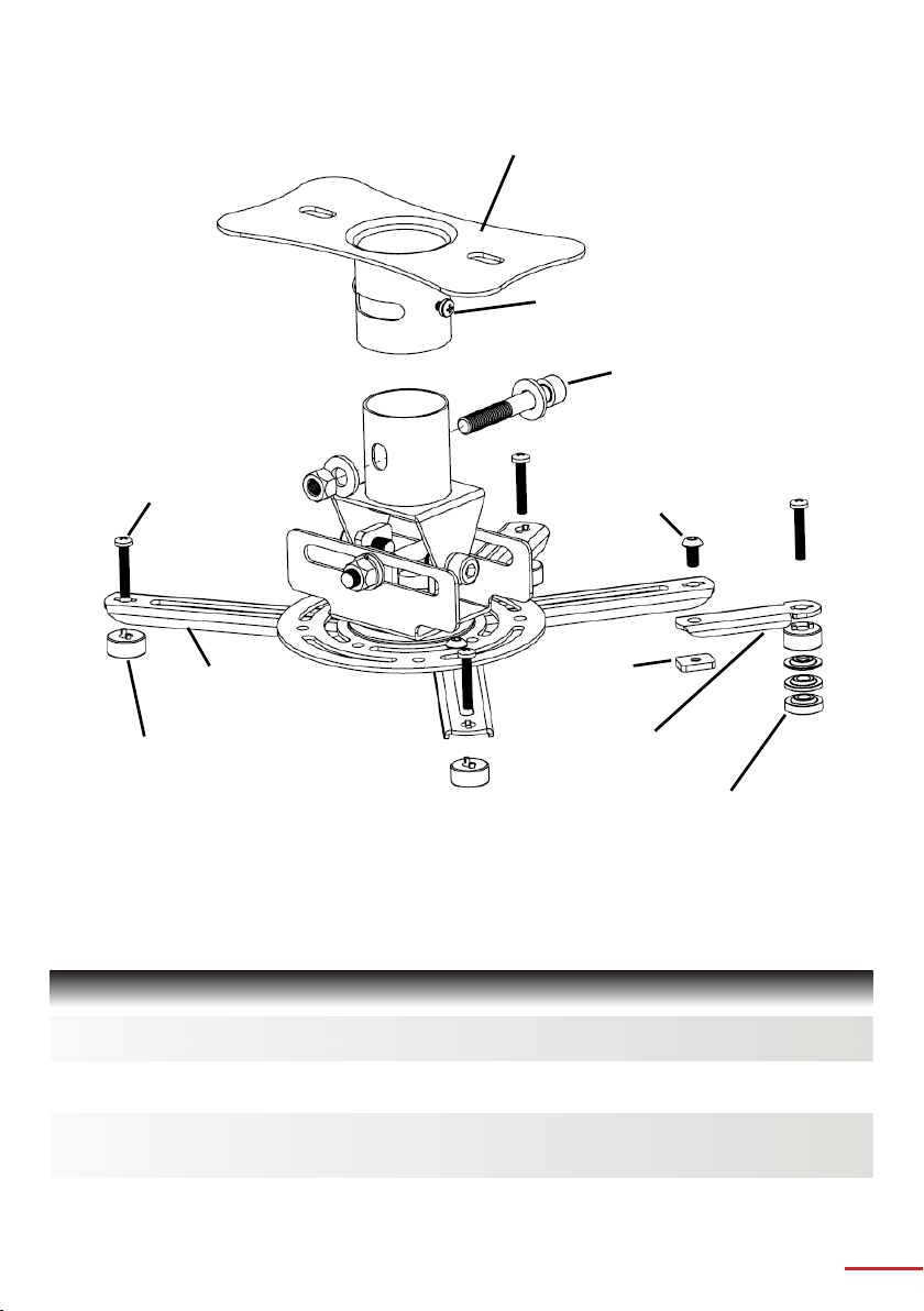
Ceiling Plate
M4x6 Cross Recessed
Screw
M8x65 Socket Cap
Screw
Cross Recessed
Screw A—I
M5x10 Socket
Button Screw
Square
Extension Bracket
Nut
(100mm)
Bottom Spacer
Extension
Bracket (50mm)
1mm, 2mm, 4mm
Washers
SPECIFICATION
Net Weight : 2.52 kg (5.56 lbs)
Dimension : 420 x 200 x 120 mm (16.5” x 7.9” x 4.7”)
Extendable Length
(Min to Max) : Min 576mm, Max 826mm (Min 22.7”, Max 32.5” )
Load Capacity : 15 kg (33 lbs)
2
Page 4

SAFETY
Assembling without the correct use of bolts and screws at designated points may result in injury and damage
to properties or the unit collapsing from its installed position. Should a malfunction occur disconnect the
power from the main socket and surround the area with ropes to prevent others from getting near it.
Check and ensure the ceiling where you install can support the weight or the projector and ceiling mounting.
All Ceiling Mounting Brackets are to be firmly secured so the unit will not drop off its installed position.
Steps should be taken to ensure the ceiling and installed unit can withstand external forces like earthquakes,
vibrations, etc.
Do not remove any bolts and screws from the Ceiling Mounting Brackets or do any changes to the Ceiling
Mounting Brackets.
Do not install near an air-conditioner. Do not install at place where there are excessive dust and smoke as
fi re could arise from these sources.
Keep the room well ventilated to prevent room temperature rising and possibilities resulting in fire.
Do not install in location where room temperature and humidity are excessively high to prevent fire. To
prevent fire, avoid contact with water
Do not apply unnecessary stress or load on the installed unit.
3
Page 5
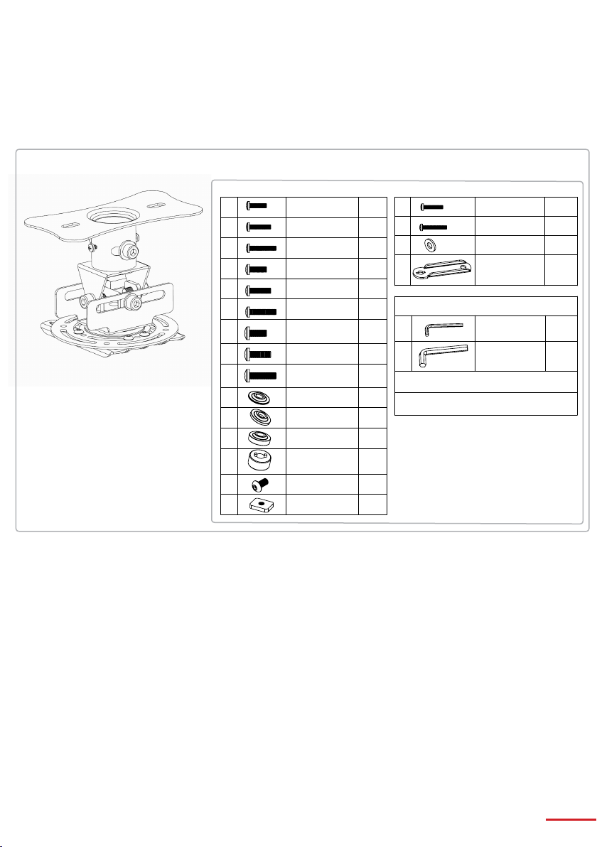
PACKAGE OVERVIEW
1. Each package should contain the parts listed and shown below
Flush Mount Assembly (x1)
Parts Bag
A
B
C
D
E
F
G
H
I
J
K
L
M
N1
N2
M4 x 15 Cross
Recessed Screw
M4 x 20 Cross
Recessed Screw
M4 x 25 Cross
Recessed Screw
M5 x 15 Cross
Recessed Screw
M5 x 20 Cross
Recessed Screw
M5 x 25 Cross
Recessed Screw
M6 x 15 Cross
Recessed Screw
M6 x 20 Cross
Recessed Screw
M6 x 25 Cross
Recessed Screw
1mm Washer
2mm Washer
4mm Washer
Bottom Spacer
M5 x 10 Socket
Button Screw
Square Nut
4 pcs 4 pcs
a
4 pcs 4 pcs
b
4 pcs 4 pcs
c
4 pcs 4 pcs
d
4 pcs
Tools Included
4 pcs
4 pcs
4 pcs
4 pcs
Tools Required for mount assembly
4 pcs
1. 1x Star / Philips Screw Driver
2. 1x 13mm Spanner
4 pcs
4 pcs
4 pcs
4 pcs
4 pcs
M3 x 15 Cross
Recessed Screw
M3 x 20 Cross
Recessed Screw
M3 Flat Washer
Extension
Bracket (50mm)
3mm Allen Key
6mm Allen Key
1 pc
1 pc
4
Page 6

SETUP AND INSTALLATION
(A) Removing the Ceiling Plate from the Flush Mount Assembly:
1. Loosen the M4x6 (x2) Cross Recessed Screw with a screw driver
2. Remove the M8x55 Socket Cap Screw and Nylock Nut from the Flush Mount Assembly as shown.
3. Removing the Ceiling Plate from the Flush Mount Assembly.
M8x55 Socket Cap Screw
Ceiling Plate
M8 Nylock Nut
Screw driver
M4x6 Cross
Recessed
Screw
6mm Allen Key
5
Page 7

SETUP AND INSTALLATION
(B) Installing the Ceiling Plate:
Choose the appropriate installation procedure depending on your ceiling type.
Masonry
8mm (5/16”)
Holes
Ceiling Plate
Timber
Beam
Ceiling Plate
Nylon Anchor
Plug
Plaster Board
*Washer
*14 Gauge Coach
Screw
Plaster
Board
3mm (1/8”) Holes
drill on Timber Beam
*Washer
*14 Gauge Coach
Screw
* Plug and Screws are only for recommendation, not supplied within package
6
Page 8

SETUP AND INSTALLATION
(C) Attaching the Flush Mount Assembly to the projector:
C.1— Loosen the M5x10mm Socket Button Cap Screws using the 3mm Allen key until you can slide the
extension brackets freely, as shown.
Extension Bracket
100mm
3mm Allen key
M5x10mm
Socket Button
Cap Screw
C.2— Place projector’s Flush Mount Assembly over the projector and align the centre of the Flush
Mount with the projector’s approximate Centre of Gravity.
Centre of Flush
Mount
This surface to be approximate parallel to
the projector front
Centre of Gravity
7
Page 9

SETUP AND INSTALLATION
C.3— Place the Bottom Spacers in between the Extension Brackets and the Projector, and align the
mounting holes as shown below.
Extension Bracket
Bottom Spacer
Bottom Spacer
Mounting hole
If the mounting holes on your projector
NOTE
are recessed, you may need to use
the additional spacers supplied in the
parts bag. Please select the appropriate
spacers according to the design of
your projector.
Note 2:
If you cannot align the 100mm Extension
Bracket to the mounting hole on your
projector, you may need to use the
additional 50mm Extension Brackets
shown in the diagram on the right.
M5x10mm
Screw
Extension Bracket
Square Nut
Bottom Spacer
8
Page 10

SETUP AND INSTALLATION
C.4— Select the correct Mounting Screws from the Parts bag and firmly screw the Flush Mount
Assembly onto your Projector.
Once this is done, the Projector Flush Mount Assembly is ready to be mounted onto the Ceiling Plate.
Mounting Screws
Bottom
Spacer
9
Page 11

SETUP AND INSTALLATION
(D) Attaching the Flush Mount Assembly to the Ceiling Plate
D.1— Connect the Short Pole to the Ceiling Plate as shown be-
Ceiling Plate
Short Pole
D.2— Insert the M8x55 Socket Cap Screw into the slot on the Ceiling Plate to lock the Flush Mount
Assembly with the M8 Nylock Nut. Tighten the M4x5 Cross Recessed Screws to balance the Flush
Mount Assembly.
M8 Nylock Nut
and Washer
Screw
Driver
M4X6 Cross
Recessed
Screw
**M8X55 Socket Cap
Screw and Washer
Tip: When the Projector required servicing, remove the
Projector via the easy disconnection point** to save time.
6mm Allen Key
10
Page 12

SETUP AND INSTALLATION
(E) Adjusting the Projector
Roll / Shift Adjustments — to make Roll/Shift adjustments, first ensure the weight of the Projector is
supported. Then loosen the M8x65mm Socket Cap Screw with the supplied 6mm Allen Key and adjust
to your desired position. Re tighten the screws firmly.
6mm Allen Key
M8X65mm
Socket Cap
Screw
Roll
Shift
Roll
Pitch Adjustment — to make Pitch adjustments, first ensure the weight of the Projector is supported.
Then loosen the M8x15mm Socket Cap Screws with the supplied 6mm Allen Key and adjust your
projector to the desired position, then tighten the screws firmly.
M8x15
Socket Cap
6mm Allen Key
Pitch
Pitch
11
Page 13

Due to continuing product development, the manufacturer reserves the right to alter specications without notice. Published: 31.03.2015
12
Page 14

13
www.optoma.com
 Loading...