

Page 1
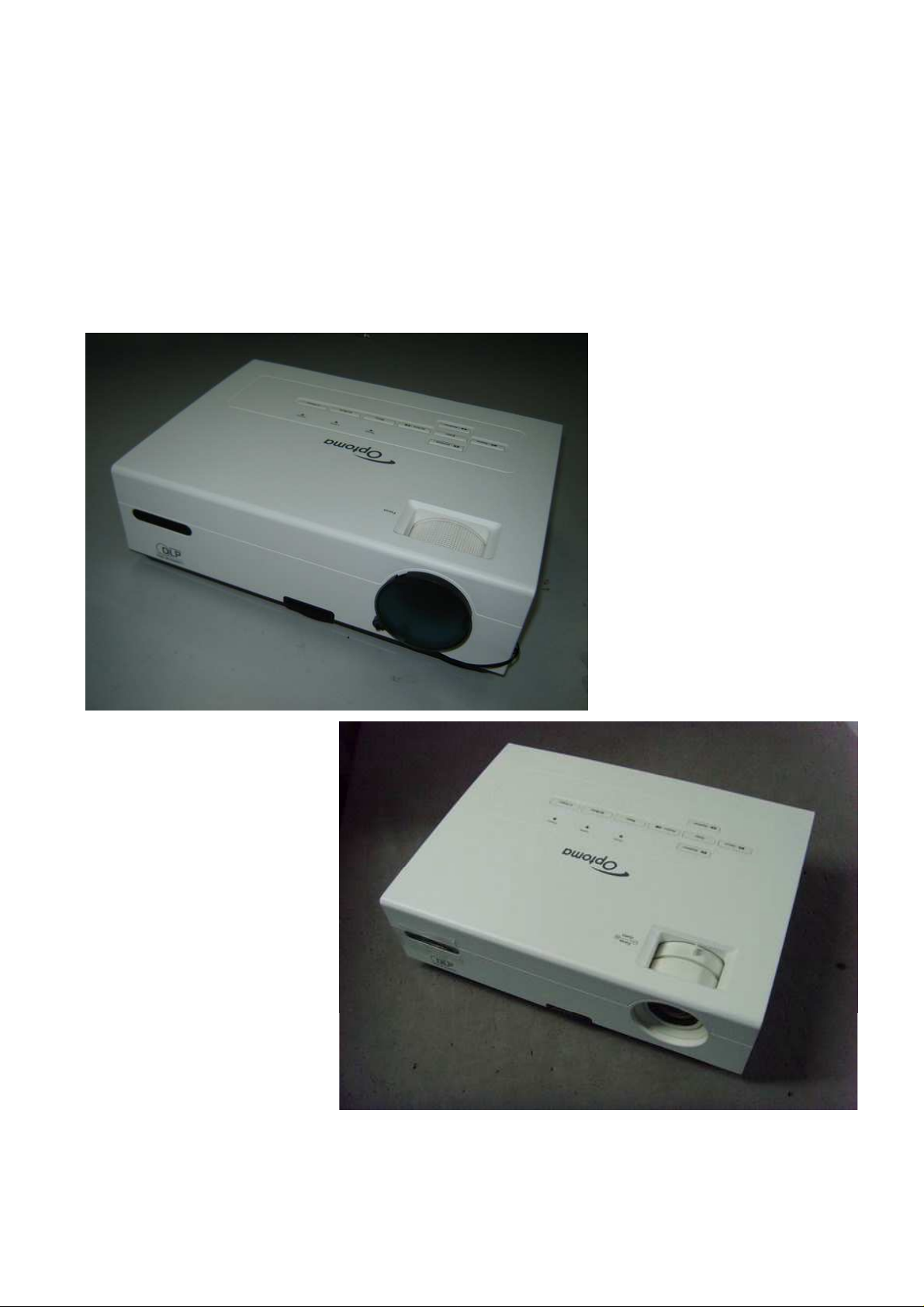
Delta Elec. Inc. ES520 & EX530 ver.02
DATA PROJECTOR
ES520
(DP-2512)
& EX530
SERVICE MANUAL
(ver.00)
(DP-3511)
Company Confidential Optoma___________________ Delta________________
1
2008/09/17
Page 2

Delta Elec. Inc. ES520 & EX530 ver.02
DLP DIGITAL PROJECTOR
Model Name: ES520 & EX530
Revision Description Date
Ver.00 Primarily 03/07/2008
Ver.01 Revised the spare part list 05/28/2008
Ver.02 Revised the spare part list, change the main board PN to 5600600785 09/17/2008
Company Confidential Optoma___________________ Delta________________
2
2008/09/17
Page 3

Delta Elec. Inc. ES520 & EX530 ver.02
CONTENTS
1.COMPLIANCE OF SAFE REPAIR.........................................................................................5
1-1.Caution During Disassembling And Assembling.............................................................5
1-2.Lamp.............................................................................................................................. 5
1-3.Lens................................................................................................................................5
1-4.Eye Safety Warnings......................................................................................................6
2.SPECIFICATIONS.................................................................................................................7
2-1.Summary Specifications................................................................................................. 7
2-2.DMD Specifications........................................................................................................ 8
2-3.Color Wheel................................................................................................................... 8
2-4.Lamp.............................................................................................................................. 8
2-5.Input/output connectors…………………………………………………………………….…8
2-6.I/O Ports Illustration........................................................................................................9
2-7.Remote Control Parts...................................................................................................10
2-8.Key Pad-Top view and LEDs…………………………………………………...………….. 12
2-9.Optical Adjustment & Image Size (ES 520)…….………………………………………....13
2-10. Optical Adjustment & Image Size (EX 530)………………………………………….….14
2-11.BLOCK DIAGRAM..................................................................................................... 16
2-12. Wire diagram………………………………………………………………………………..17
3.TROUBLE SHOOTING....................................................................................................... 18
4.DISASSEMBLY AND ASSEMBLY (ES 520)....................................................................... 25
.. DISASSEMBLY AND ASSEMBLY (EX 530)....................................................................... 41
5.Flash Upgrade Flow............................................................................................................ 58
5-1.Projector USB Drivers Installation Guide…………………………………………………..58
Appendix-A How to clear the USB enumeration registry?............................................67
Appendix-B Projector USB status on Windows Device Manager………………………69
5-2.DLP Projector Flash-Tool (firmware) User Guide…………………….……….…………..70
5-3.Start with Flash-Tool………………………………………………………………………....71
5-4.Starting and Shutting down the Projector……………………………………………….....76
5-5.Setting an Access Password (Security Lock)………………………………….…………..77
5-6.SETUP / Advanced………………………………………………………………………..…81
5-7.Security Timer………………………………………………………………………………...82
5-8.Options Menu…………………………………………………………………………………83
5-9.OPTIONS / Advanced…………………………….………………………………………….84
Company Confidential Optoma___________________ Delta________________
3
2008/09/17
Page 4

Delta Elec. Inc. ES520 & EX530 ver.02
6. Calibration…………………………….………………………………………….………………..85
7. Color Border Adjustment………………………………………………………………………...91
8. Projection Lamp…………………………………………………………………………………..92
9. Cleaning…………………………………………………………………………………………...95
10.SERVICE NOTE............................................................................................................... 96
10-1.Service Note Description........................................................................................... 96
10-2.Power & READY LED Blink Code Message.............................................................. 97
10-3.Factory Preset Display Modes................................................................................... 98
11.Spare Part List ................................................................................................................ 100
Company Confidential Optoma___________________ Delta________________
4
2008/09/17
Page 5

Delta Elec. Inc. ES520 & EX530 ver.02
1. COMPLIANCE OF SAFE REPAIR
Be sure to read this Service Manual before providing services. In the projector, full
consideration is taken to ensure safety for fire, electric shock, injury, harmful radiation, and
substance. Therefore, observe the notice described in this Service Manual so that safety is
kept when providing services. Moreover, be sure to observe the notice described in the
Instruction Manual.
Pay attention to the following items during service inspection.
1-1 Cautions during disassembling and assembling
1. This equipment contains parts under high voltage. When making repairs, etc.
Be sure to pull out the power plug beforehand to insure safety.
2. Parts may be very hot immediately after use.
Make sure the equipment has cooled off sufficiently before carrying out repairs.
3. Make sure that parts and screws and wiring, etc. are returned to their original positions.
Tube, tape and other insulation materials have been used for safety reasons.
The internal wiring has been designed to avoid direct contact with hot parts or parts under
high voltage when using clamps or other tools.
4. The parts used in this device have special safety features such as flame-resistance and
anti-voltage properties. When replacing parts, always use parts supplied from the factory.
5. After finishing operations make sure that all parts and wires have been returned to their
original position and that there has been no deterioration of the area around the location that
was worked on.
6. Be sure to use a grounding strap (wrist band) during repair and inspection.
1-2 Lamp
During current conduction, the lamp is in the high-temperature state. In this case, pay
careful attention because a high voltage is used. When replacing a lamp, replace it after
confirming that the lamp has gotten cold sufficiently.
1-3 Lens
Do not look into a lens during projection. This damages your eyes.
Company Confidential Optoma___________________ Delta________________
5
2008/09/17
Page 6

Delta Elec. Inc. ES520 & EX530 ver.02
1-4 Eye Safety Warnings
Avoid staring directly into the projector’s beam of light at all times.
1.
Minimize standing facing into the beam. Keep your back to the beam as much as
2.
possible.
3.Using a stick or laser pointer is recommended to avoid the need for the presenter
to enter the beam.
4.Ensure that projectors are located out of the line of sight from the screen to the
audience; this ensures that, when presenters look at the audience, they do not also
have to stare at the projector lamp.
5.The best way to achieve this is by ceiling-mounting the projector rather than placing it
on
floor
or table top.
6.When projector is used in a classroom, adequately supervise students when they are
asked to point out something on the screen.
7.In order to minimize the lamp power needed, use room blinds to reduce ambient light
levels.
Company Confidential Optoma___________________ Delta________________
6
2008/09/17
Page 7

Delta Elec. Inc. ES520 & EX530 ver.02
2. SPECIFICATIONS
2-1. Summary Specifications
Model ES520 (DP-2512) EX530 (DP-3511)
Display type
Resolution SVGA 800X600 Native (4:3) XGA 1024x768 Native (4:3)
Color Brilliant Color
Projection distance 1.5 meters ~ 10 meters 1.0 meters ~ 10 meters
Projection screen size
Projection lens
Thro 1.15:1
Vertical keystone
correction
Projection methods Front / Rear-Desktop & Front / Rear-Ceiling
Data compatibility
SDTV/EDTV/ HDTV
Video compatibility NTSC/NTSC 4.43, PAL/PAL-M/PAL-N,SECAM
H-Sync 15, 30 – 91.4 KHz
TI DMD Type A,12° 0.55inches, SVGA Dark Chip 1 TI DMD Type A,12° 0.55inches, XGA Dark Chip 2
36” to 243” (overdrive to 300”) 23” to 255” (overdrive to 300”)
Manual focus Manual focus / Manual zoom
+/- 15 degrees ; +/- 30 vertical stepping in OSD
IBM PC or compatibles
(VGA, SVGA, XGA, SXGA, UXGA), Mac
480i/576i, 480p/576p, 720p, 1080i
V-Sync 43 - 87 Hz
Safety certification
Operation temperature
Dimensions / Weight
AC Input
Power consumption
Stand By
Lamp
Audio speaker
PC
Video
Audio
Security
FCC (class B), UL/CUL, ICES-003(Class B), CE, TUV-GS, CB report, CCC, EK, PSB
5° ~ 35°C
280 mm (W) x 80 mm (H) x 205 mm (D) / 5.6lb (2.5kg)
AC Universal 110 ~ 240 @50~60Hz , Typical @110 VAC (100~240)/±10%
Typical 230W (standard mode); Typical 200W (ECO mode)
< 5 watts @ 110Vac
E20.6 / 180W
1W / 8 ohm mono speaker
VGA in (Compatible with HDTV component YPbPr / SCART)
Composite video (RCA X 1)
S-Video (DIN)
Input: R / L (RCA X 2) , Out: Mini-Jack X 1
Kensington lock
Company Confidential Optoma___________________ Delta________________
7
2008/09/17
Page 8
Delta Elec. Inc. ES520 & EX530 ver.02
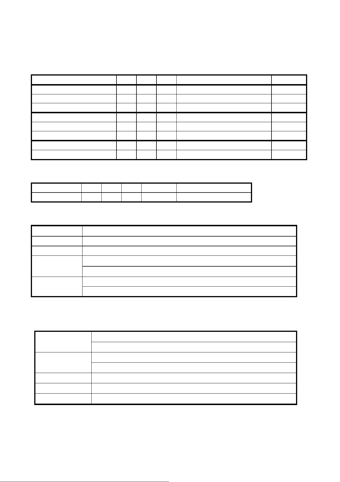
2-2.DMD Specifications
Unit Min. Max. Typical Notes
DMD type (ES520) TI 0.55" SVGA 12 deg LVDS Type A Dark chip 1
Number of Columns (ES520) Pixel 800
Number of Rows (ES520) Pixel 600
DMD type (EX530)
Number of Columns (EX530) Pixel 1024
Number of Rows (EX530) Pixel 768
Panel Operating Temp.
Ambient Temp
℃
℃
10 65
25
TI 0.55" XGA 12 deg LVDS
Type A
2-3.Color Wheel
Spec.
Color Segment
Unit Min. Max. Typical Notes
RYGWB 82/29/80/91/78 (44mm)
2-4. Lamp
Vendor
Type
Lamp Life
Lamp Power
Description
OSRAM
E20.6 180W
Standard Mode , 3000 Hours Standard @ 180W, 50% Survival Rate
ECO Mode , 4000 Hours Typical @ 150W, 50% Survival Rate
Normal: 180W±3%@Vo from 50V to 120V
ECO: 150W±3%@Vo from 50V to 120V
Dark chip 2
2-5. Input/output connectors
PC
VGA in (Compatible with HDTV component YPbPr / SCART)
USB (Service Only)
Composite video (RCAx1)
Video
S-Video (Mini-DIN)
RS232 DB9
Audio Input: R / L (RCA X 2) , Out: Mini-Jack X 1
Security Kensington slot
Company Confidential Optoma___________________ Delta________________
8
2008/09/17
Page 9
Delta Elec. Inc. ES520 & EX530 ver.02
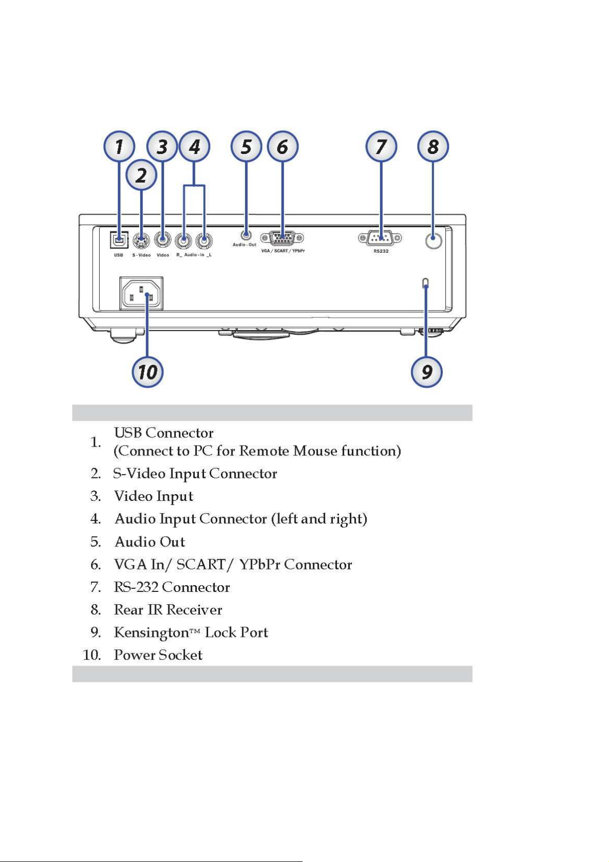
2-6. I/O Ports Illustration about Projector
Note:
If your video equipment has both S-VIDEO and RCA jacks (composite video) connect to the
S-VIDEO connector. S-VIDEO provides a better quality signal
Company Confidential Optoma___________________ Delta________________
9
2008/09/17
Page 10
Delta Elec. Inc. ES520 & EX530 ver.02
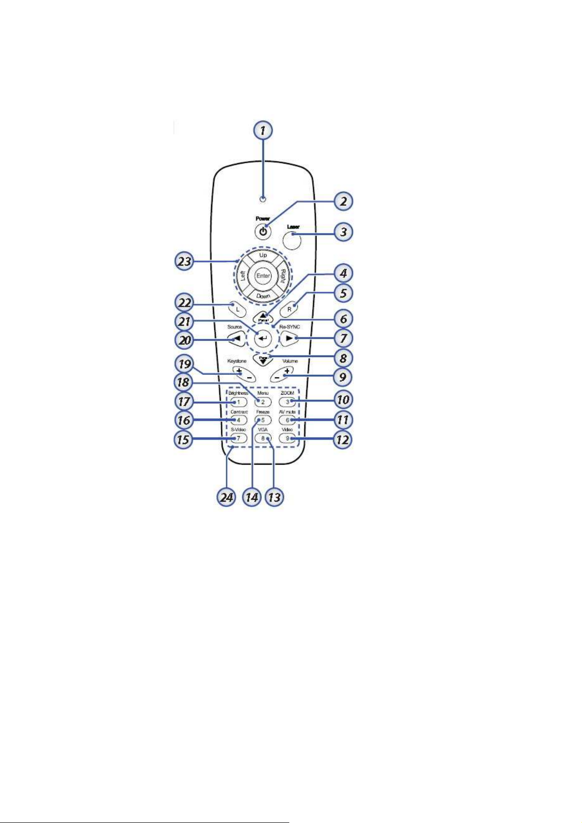
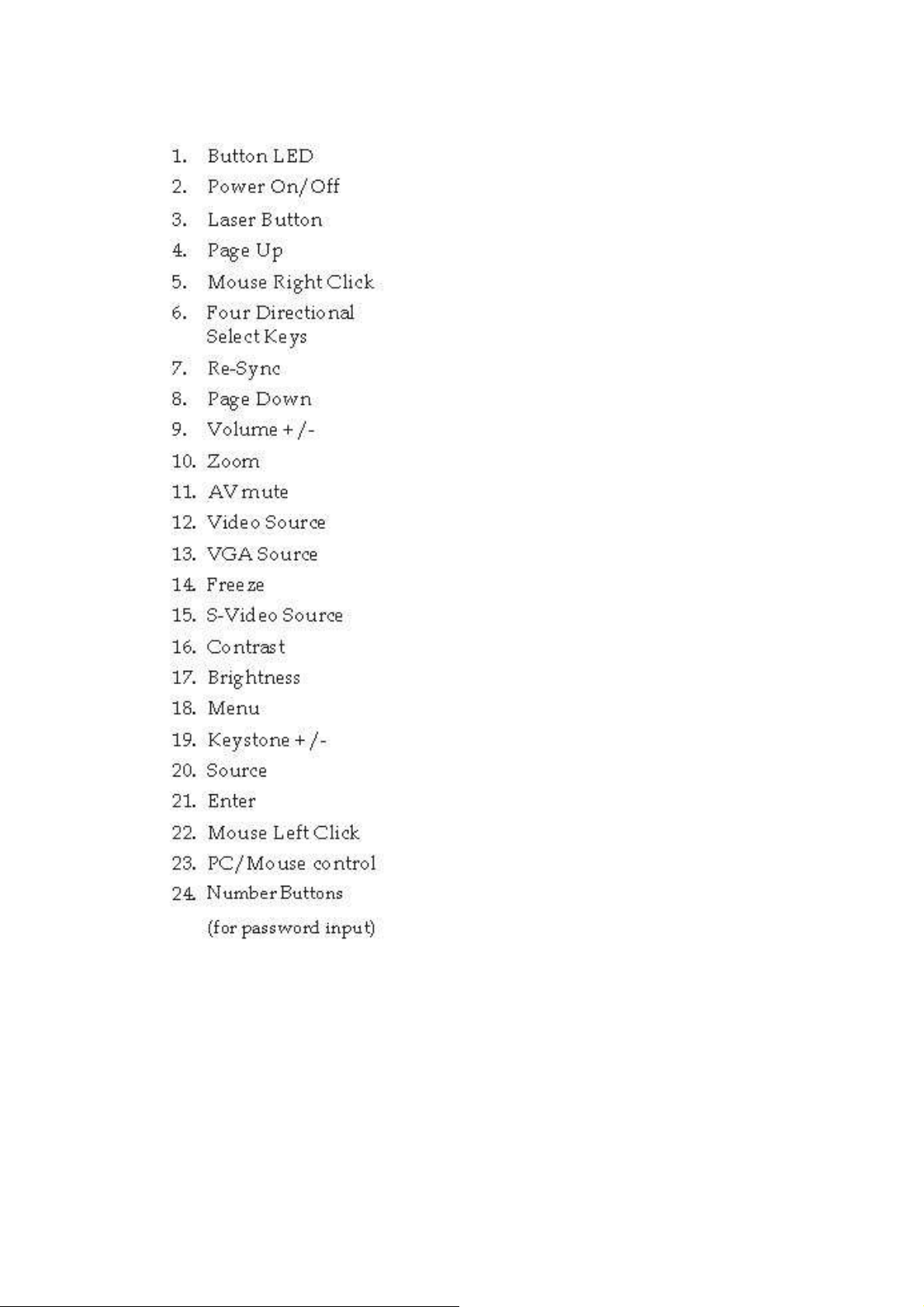
2-7. Remote Control Parts
Important:
1. Avoid using the projector with bright fluorescent lighting turned on. Certain high-frequency
fluorescent lights can disrupt remote control operation.
2. Be sure nothing obstructs the path between the remote control and the projector. If the path
between the remote control and the projector is obstructed, you can bounce the signal off
certain reflective surfaces such as projector screens.
3. The buttons and keys on the projector have the same functions as the corresponding
buttons on the remote control. This user’s manual describes the functions based on the remote
control.
Company Confidential Optoma___________________ Delta________________
10
2008/09/17
Page 11
Delta Elec. Inc. ES520 & EX530 ver.02
Remote Control Operating Range
The remote control uses infrared transmission to control the projector. It is not necessary to
point the remote directly at the projector. Provided you are not holding the remote
perpendicular to the sides or the rear of the projector, the remote will function well within a
radius of about 10 meters (33 feet) and 30 degrees above or below the projector level.
Company Confidential Optoma___________________ Delta________________
11
2008/09/17
Page 12
Delta Elec. Inc. ES520 & EX530 ver.02
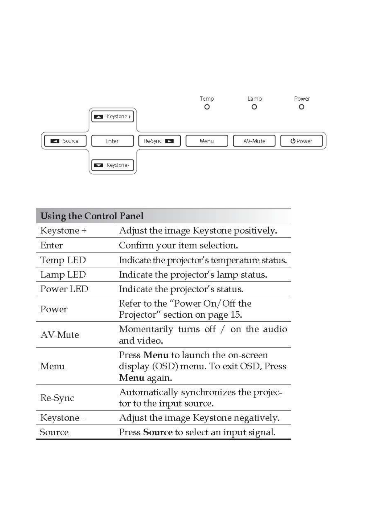
2-8. Key Pad -- Top view and LEDs
Company Confidential Optoma___________________ Delta________________
12
2008/09/17
Page 13
Delta Elec. Inc. ES520 & EX530 ver.02
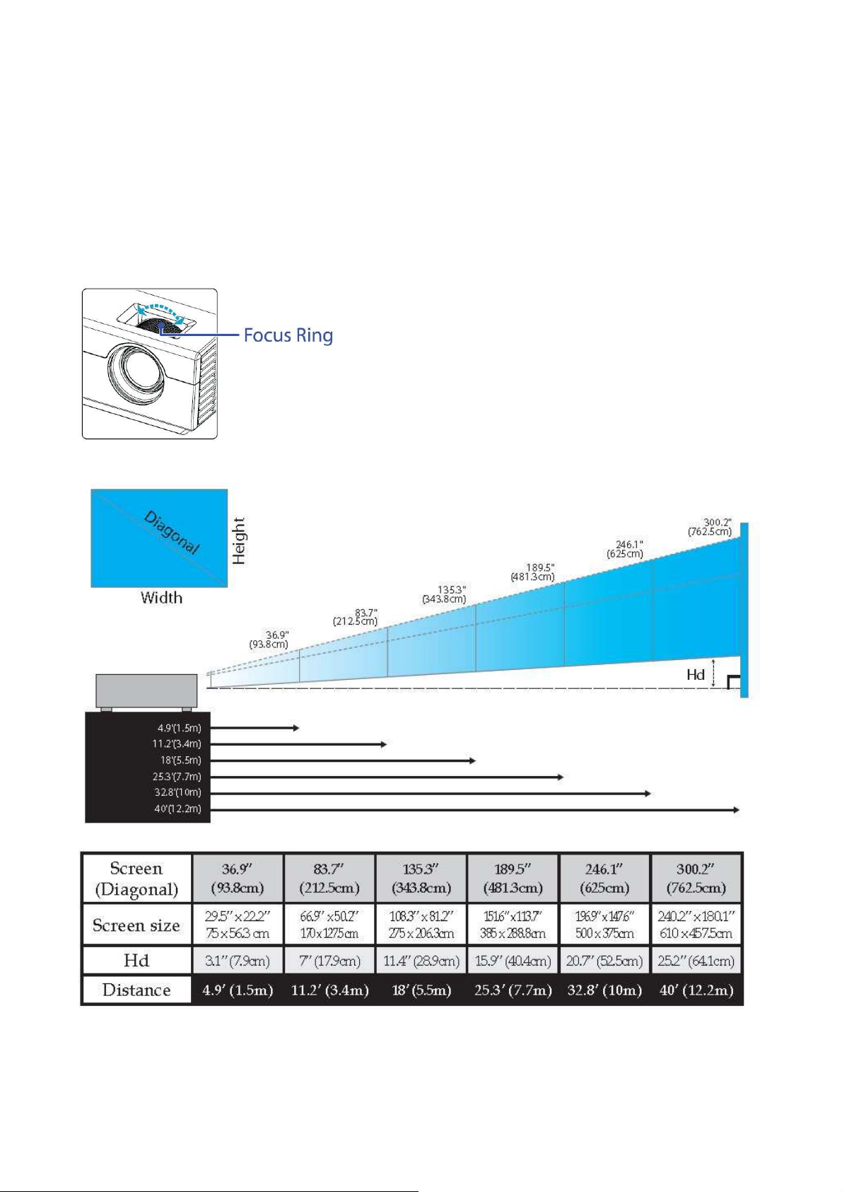
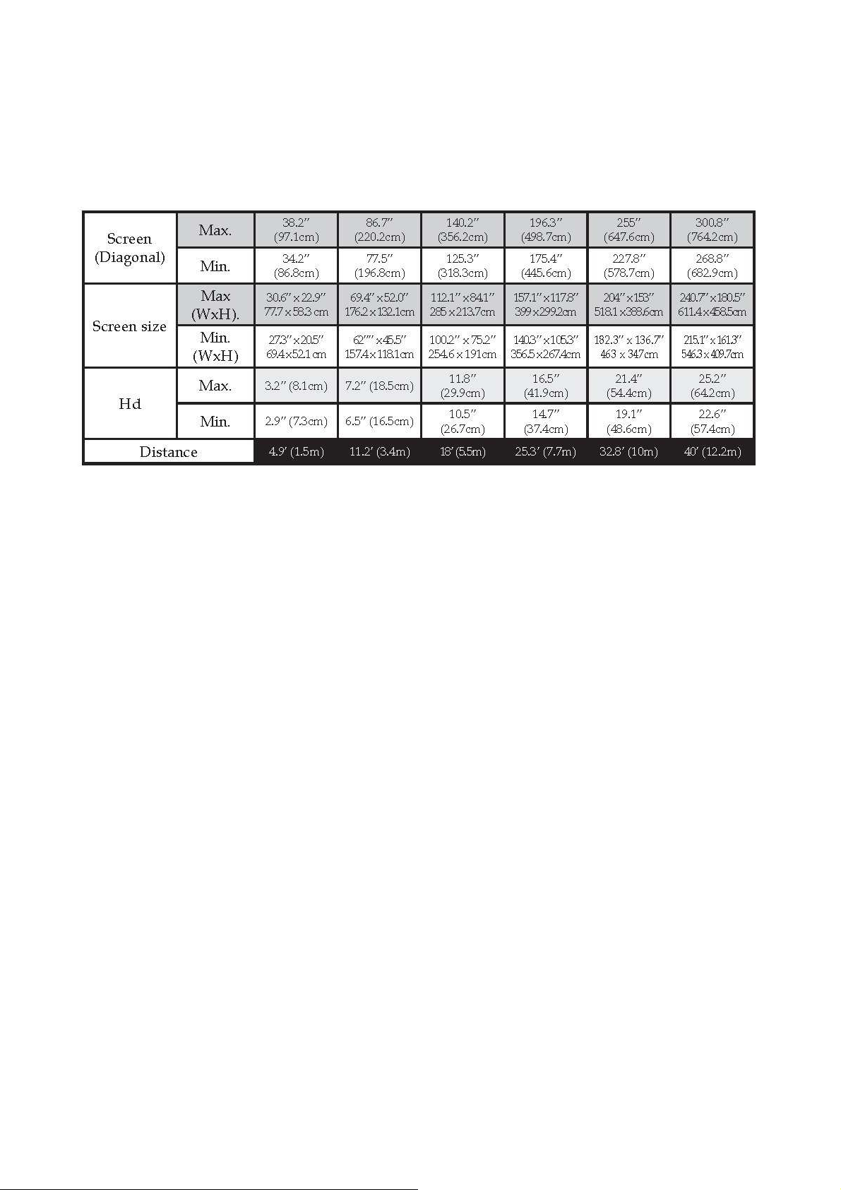
2-9. Optical Adjustment & Image Size (ES 520)
Adjusting the Focus (Fixed Zoom Series)
The Fixed Zoom Series’ lens is
fixed
and does not provide a zoom function.
To focus the image, rotate the focus ring until the image is clear.
The projector will focus at distances from 4.9 to 40 feet (1.5 to 12.2 meters).
Adjusting Projection Image Size
Company Confidential Optoma___________________ Delta________________
13
2008/09/17
Page 14
Delta Elec. Inc. ES520 & EX530 ver.02
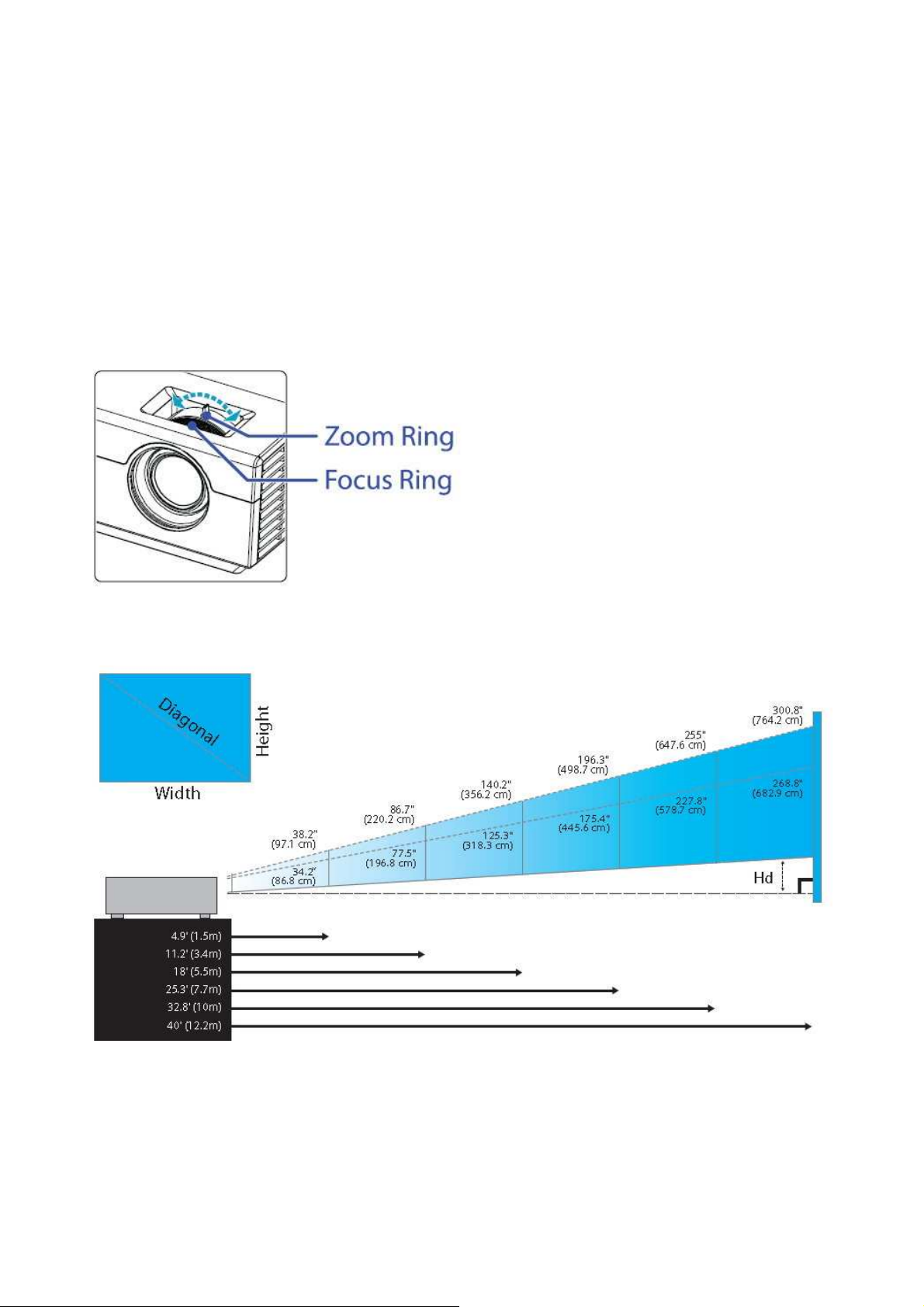
2-10. Optical Adjustment & Image Size (EX 530)
Adjusting the Zoom / Focus (Zoom Series)
You may turn the zoom ring to zoom in or out.
To focus the image, rotate the focus ring until the image is clear.
The projector will focus at distances from 4.9 to 40 feet (1.5 to 12.2 meters).
Adjusting Projection Image Size
Company Confidential Optoma___________________ Delta________________
14
2008/09/17
Page 15
Delta Elec. Inc. ES520 & EX530 ver.02
Company Confidential Optoma___________________ Delta________________
15
2008/09/17
Page 16
Delta Elec. Inc. ES520 & EX530 ver.02
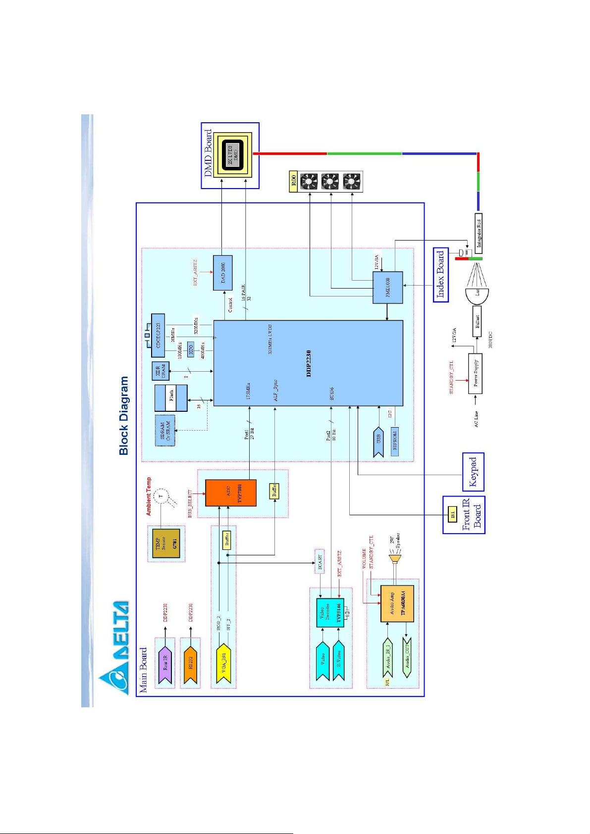
2-11. Block Diagram
Company Confidential Optoma___________________ Delta________________
16
2008/09/17
Page 17
Delta Elec. Inc. ES520 & EX530 ver.02
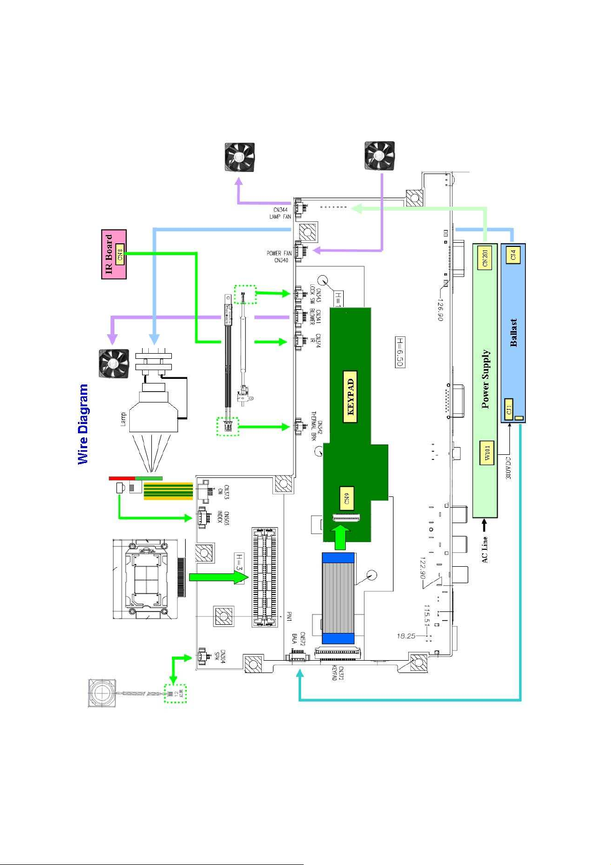
2-12. Wire diagram
Company Confidential Optoma___________________ Delta________________
17
2008/09/17
Page 18
Delta Elec. Inc. ES520 & EX530 ver.02
Waiting
POWER
: 7 Blinks
Over Temp LED
:
ON
•
Press
“
power key
”
Power ON
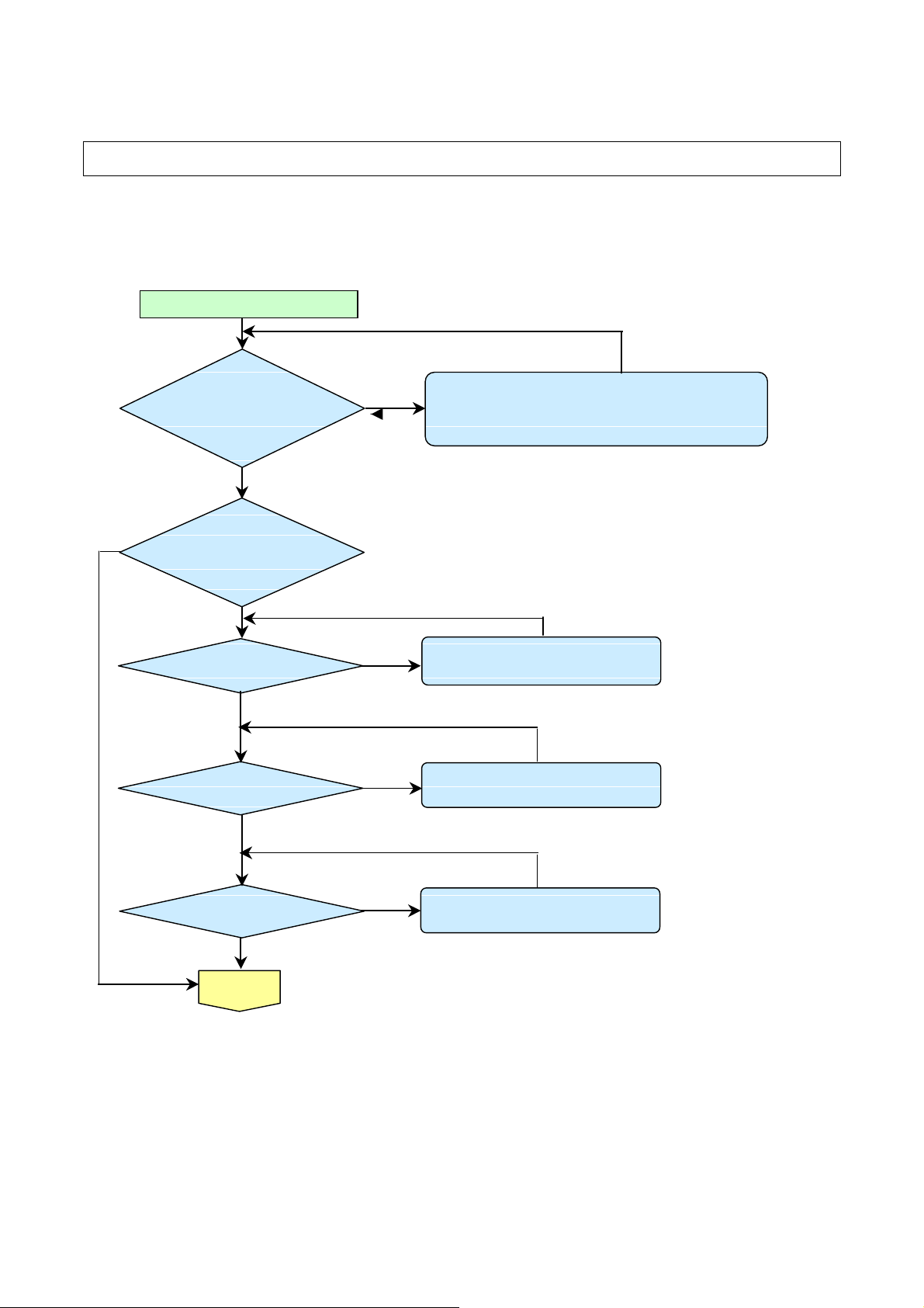
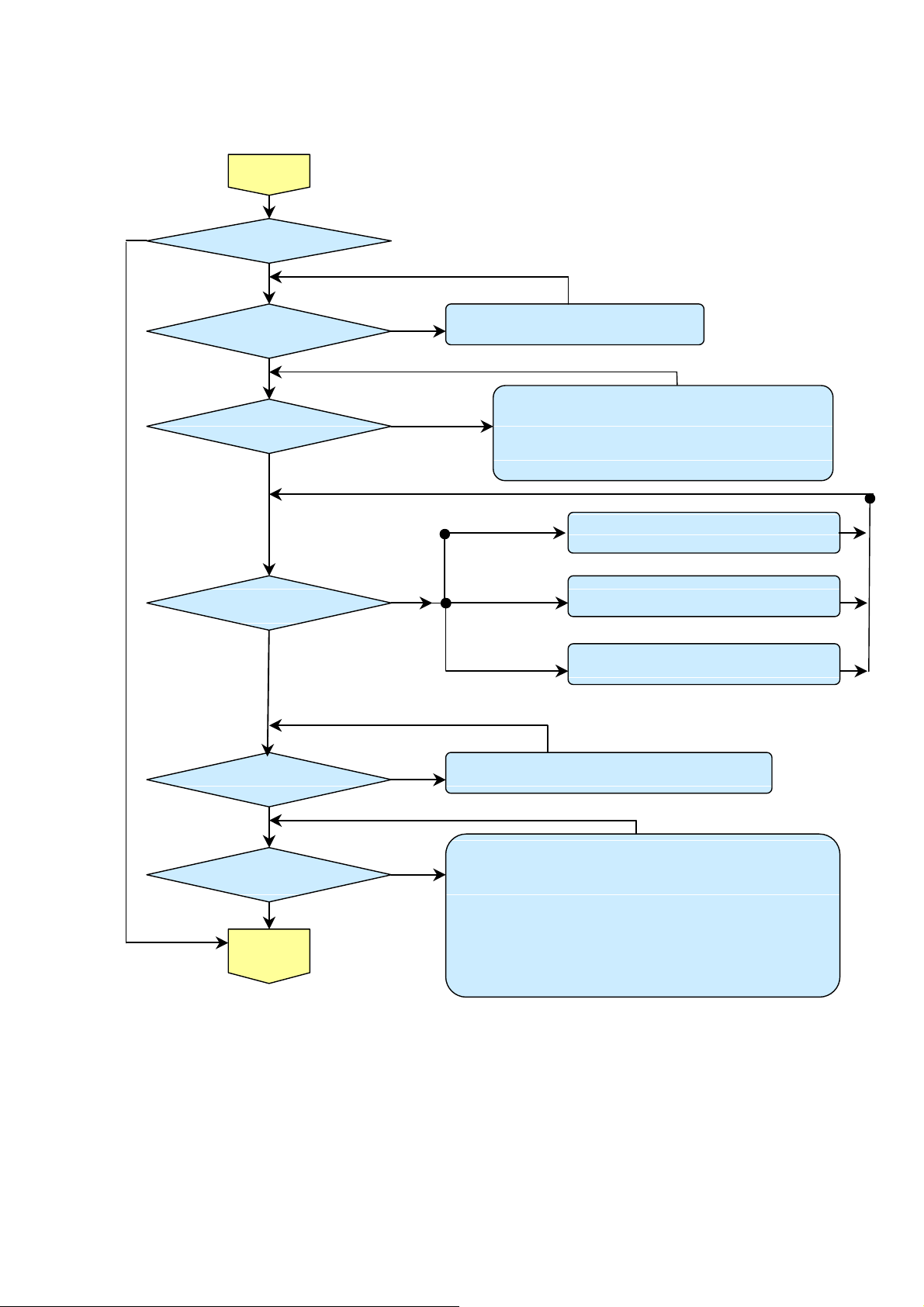
3. TROUBLE SHOOTING
By checking operations during normal usage time, it is possible to carry out judgments on
malfunction to a certain extent. Carry out the following checks before disassembling the
equipment.
Yes
Connect the power cord
Yes
POWER: Light
READY : Light
Standy-by-ready
Yes
POWER: Light
READY : OFF
No
No
No
Yes
Yes
No
• Cable of Power Supply Unit and thermostat Ass’y.
Check the connection of Power Supply (CON900 to CN201)
• Power Supply Unit malfunction
• Check keypad connection
No
•Lamp Cover A’ssy is not attached
•Switch (CN343) is open
No
•Connector (CN342) disconnected.
•Thermal sensor PWB Ass’y check.
Company Confidential Optoma___________________ Delta________________
18
No
POWER:8 Blinks
Yes
Power On
No
Yes
•DMD chip error.
•DMD Board PWB Ass’y check.
2008/09/17
Page 19
Delta Elec. Inc. ES520 & EX530 ver.02
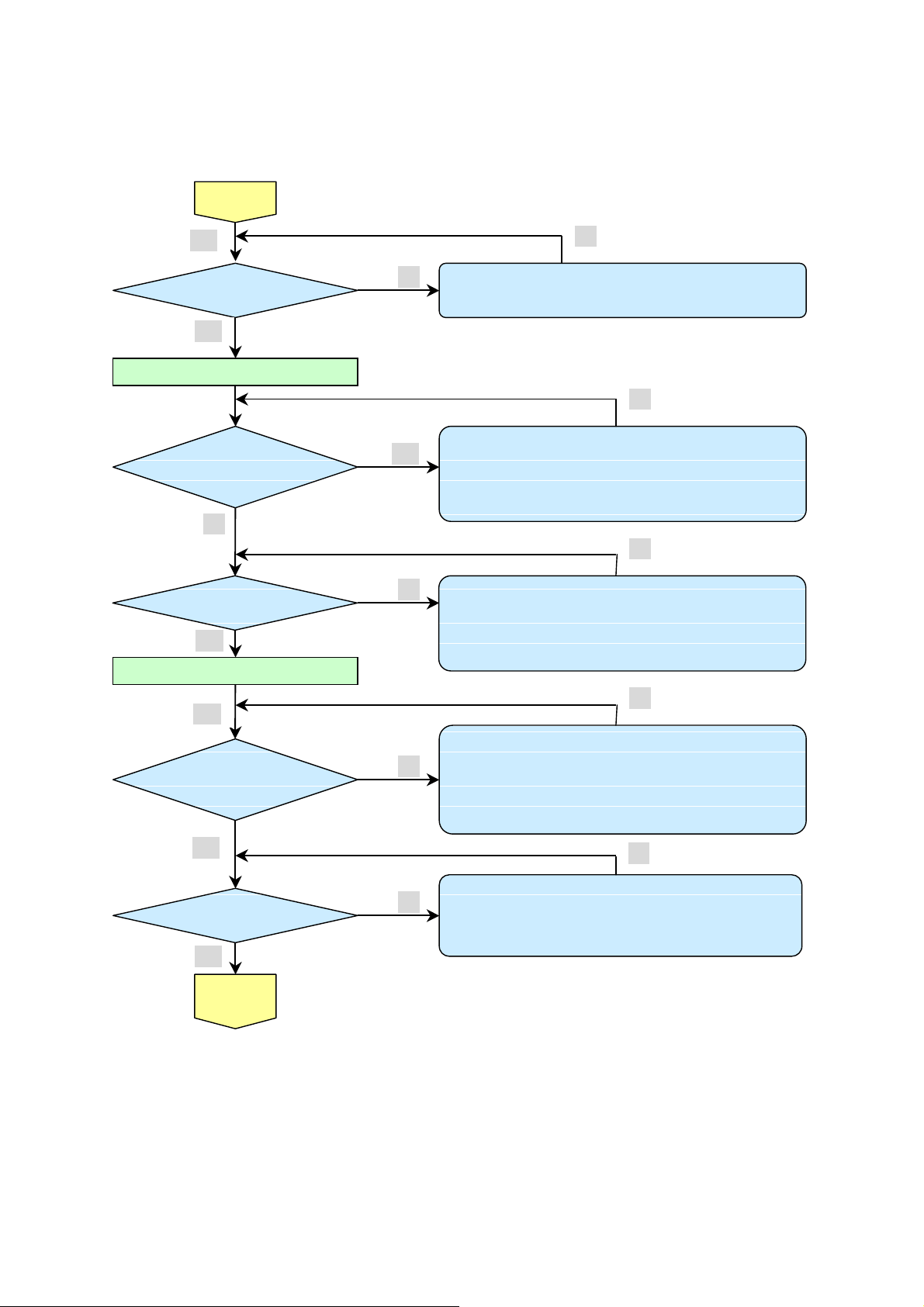
Blinks
POWER
: 4 Blinks
Blinks
POWER:
9 Blinks
No lighting operation sound (ignition sound) exists.
(CN373) or
lighting operation sound (ignition sound)
Turn the
Image
Blinks
Yes
power ON
Yes
The lamp is ON
No
•Thermal Break Sensor error
Yes
•Thermal Break Sensor disconnected.
No
No
POWER: 5 Blink
No
Yes
No
Lamp does not light
exists.
• Main Board and Ballast Board Ass’y malfunction
Ballast Connector (CJ4) or LVPS unit (CJ1) or
•
MB(CN572)disconnected
• Lamp failure (Lamp is broken, damaged, or burst)
:
No
LAMP
1
::::
• Connector CN344 of Fan disconnected
• Lamp fan malfunction
POWER: 6 Blinks
No
Yes
LAMP
2
::::
LAMP
3 Blinks
::::
• Connector CN340 of Fan disconnected
• Power fan malfunction
• Connector CN341 of Fan disconnected
• Blower fan malfunction
POWER: 7
Yes
•Lamp Cover is not attached.
•Switch (CN343) is open malfunction
No
No
Display
Yes
Lamp does not light
• Flexible cable of Color Wheel Ass’y is disconnected
broken.
• Color Wheel Ass’y malfunction (does not rotate).
• Main Board Ass’y malfunction (Color Wheel Ass’y does not rotate).
• Power Supply Unit malfunction.
• Index board malfunction (color wheel turns fast).
• C/W sensor PWB Ass’y (CN7) / MB PWB (CN503) is disconnected
or broken.
No
No
:
Company Confidential Optoma___________________ Delta________________
19
2008/09/17
Page 20
Delta Elec. Inc. ES520 & EX530 ver.02
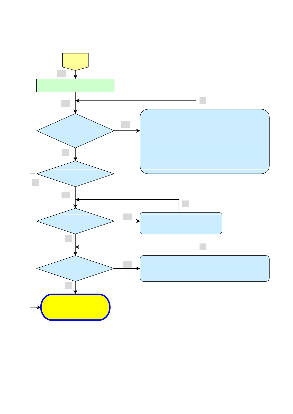
Projector logo
screen display
• DMD Set malfunction
Still dark after the
than 1min
g, resolution, etc.)
Check the
I
mage
display
Speaker work
normally
Image
Display
Confirmation with none-signal state
Yes
Yes
lamp is on for more
No
Menu display
Yes
Input each signal
No
Yes
No
No
• CW Sensor Board Ass’y malfunction
• Main Board Ass’y malfunction
No
• Lamp deterioration (malfunction/usage time)
• Power Supply Unit malfunction
(No change occurs even after lamp replacement.)
• DMD Set malfunction
(No change occurs even after lamp replacement.)
No
• Remote controller set malfunction, Low battery,
and outside operation rang
• Main Board Ass’y malfunction
• Connector (CN374)、(CN8 of IR PWB) disconnected
• IR PWB Ass’y malfunction
Company Confidential Optoma___________________ Delta________________
20
Yes
normally
Yes
Yes
projection
Screen
• Check the pattern generator setting is wrong
• Main Board Ass’y malfunction
No
• DMD Set malfunction
• Setting on PC side(external output settin
• Cable malfunction (disconnection and pins broken)
• Connector (CN304) disconnected
No
• Speaker Ass’y malfunction
• Main Board Ass’y malfunction
No
No
2008/09/17
Page 21
Delta Elec. Inc. ES520 & EX530 ver.02
Check the
Check using all black/white screens with
Are abnormalities
Does the lamp
oper
ation?
Over Temp LED:
Light again?
System OK
• Temperature protector operated due to the increase in
• Temperature protector operated due to blocked suction and
No
projection
Screen
Yes
PC connection
Yes
noticeable on
projection screen?
No
go off during
Yes
No
• Black lines on screen (horizontal and vertical)
Yes
→ DMD Set malfunction
• Missing pixels (Missing white: 1 or more, missing black: 5 or
more, or sequence missing pixels)
→ DMD Set malfunction
• Shadows on screen
→
Dirt on DMD/projection lens surface
• Bluish shadows on corners of screen (during white screen
display)
→
Shifted optical axis of Lens Base Unit
Is LAMP
No
ON
No
Normal operation
Yes
Yes
• Lamp malfunction
• Power Supply Unit malfunction
temperature based on operating environment
exhaust holes or dirty fan
No
No
Company Confidential Optoma___________________ Delta________________
21
2008/09/17
Page 22

Delta Elec. Inc. ES520 & EX530 ver.02
Common problems and solutions
These guidelines provide tips to deal with problems you may encounter while using the
projector. If the problem remains unsolved, contact your dealer for assistance.
Often after time spent troubleshooting, the problem is traced to something as simple as a loose connection.
Check the following before proceeding to the problem-specific solutions.
• Use some other electrical device to confirm that the electrical outlet is working.
Ensure the projector is turned on.
•
• Ensure all connections are securely attached.
Ensure the attached device is turned on.
•
• Ensure a connected PC is not in suspending mode.
Ensure a connected notebook computer is configured for an external display. (This is usually done by pressing an
Fn-key combination on the notebook.)
Image Problems
Problem: No image appears on the screen
1. Verify the settings on your notebook or desktop PC.
2. Turn off all equipment and power up again in the correct order.
Problem: The image is blurred
1. Adjust the Focus on the projector.
2. Press the Re-sync button on the remote control or projector.
3. Ensure the projector-to-screen distance is within the 10-meter (33-feet) specified range.
4. Check that the projector lens is clean.
Problem: The image is wider at the top or bottom (trapezoid effect)
1. Position the projector so it is as perpendicular to the screen as possible.
2. Use the Keystone button on the remote control or projector to correct the problem.
Problem: The image is reversed
Check the Projection setting on the Setup menu of the OSD.
Company Confidential Optoma___________________ Delta________________
22
2008/09/17
Page 23

Delta Elec. Inc. ES520 & EX530 ver.02
Problem: The image is streaked
1. Set the Frequency and Phase settings on the Computer menu of the OSD to the default
settings.
2. To ensure the problem is not caused by a connected PC’s video card, connect to another
computer.
Problem: The image is flat with no contrast
Adjust the Contrast setting on the Image menu of the OSD.
Problem: The color of the projected image does not match the source image.
Adjust the Color Temperature and Gamma settings on the Image menu of the OSD.
Lamp Problems
Problem: There is no light from the projector
1. Check that the power cable is securely connected.
2. Ensure the power source is good by testing with another electrical device.
3. Restart the projector in the correct order and check that the Power LED is still green.
4. If you have replaced the lamp recently, try resetting the lamp connections.
5. Replace the lamp module.
6. Put the old lamp back in the projector and have the projector serviced.
Problem: The lamp goes off
1. Power surges can cause the lamp to turn off. Re-plug power cord. When the Ready LED is
on, press the power button.
2. Replace the lamp module.
3. Put the old lamp back in the projector and have the projector serviced.
Company Confidential Optoma___________________ Delta________________
23
2008/09/17
Page 24

Delta Elec. Inc. ES520 & EX530 ver.02
Remote Control Problems
Problem: The projector does not respond to the remote control
1. Direct the remote control towards remote sensor on the projector.
2. Ensure the path between remote and sensor is not obstructed.
3. Turn off any fluorescent lights in the room.
4. Check the battery polarity.
5. Replace the batteries.
6. Turn off other Infrared-enabled devices in the vicinity.
7. Have the remote control serviced.
Audio Problems
Problem: There is no sound
1. Adjust the volume on the remote control.
2. Adjust the volume of the audio source.
3. Check the audio cable connection.
4. Test the source audio output with other speakers.
5. Have the projector serviced.
Problem: The sound is distorted
1. Check the audio cable connection.
2. Test the source audio output with other speakers.
Company Confidential Optoma___________________ Delta________________
24
2008/09/17
Page 25
Delta Elec. Inc. ES520 & EX530 ver.02
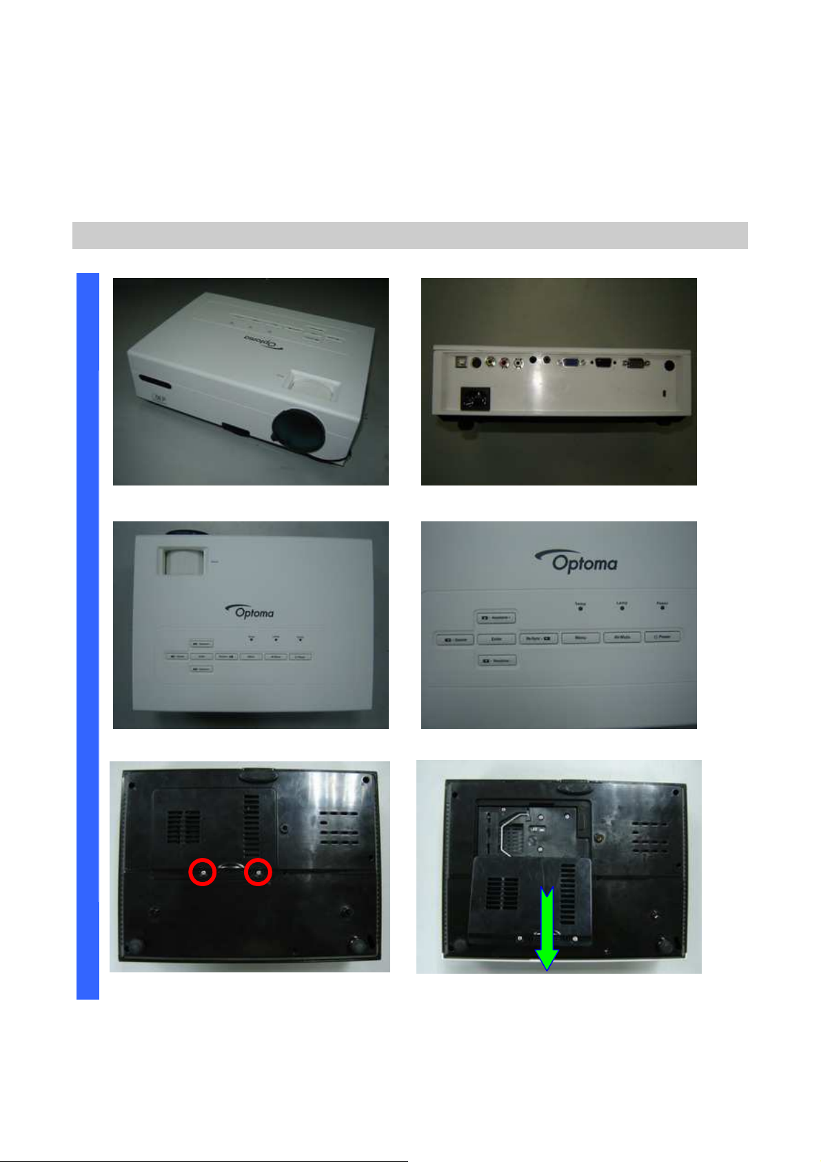
D
a. ES520 (DP-2512)
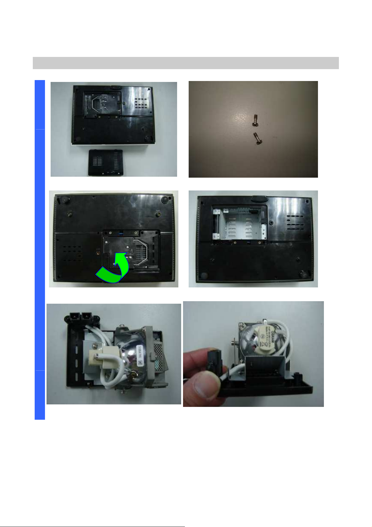
Removing the Lamp Cover and Lamp Module
I
4.DISASSEMBLY AND ASSEMBLY
S
A
S
S
E
M
B
L
Y
Look the full set projector. Look at the IO side.
Look at the case of top side. Look at the keypad of top side.
Loose these two screws. Remove and take out the lamp cover.
Company Confidential Optoma___________________ Delta________________
25
2008/09/17
Page 26
Delta Elec. Inc. ES520 & EX530 ver.02
D
Removing the Lamp Cover and Lamp Module
I
S
A
S
Remove the lamp cover. Loose two screws and take out (S01).
S
E
M
B
L
Y
Remove the lamp modules. Look the bottom case.
Look the Lamp #1.
Look the Lamp #2.
Company Confidential Optoma___________________ Delta________________
26
2008/09/17
Page 27
Delta Elec. Inc. ES520 & EX530 ver.02
D
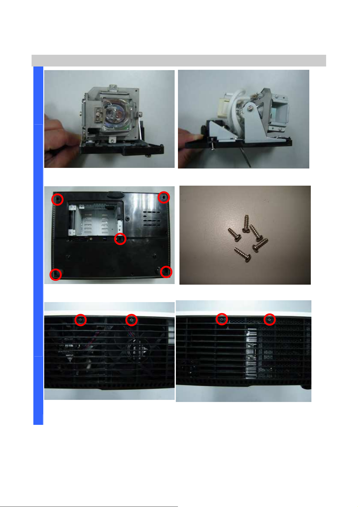
Removing the Lamp Module and Top Cover
I
S
A
S
S
E
M
B
L
Y
Look the Lamp #3. Look the Lamp #4.
Remove the five screws. Look these five screws (
S02)
.
Remove the two screws.
Company Confidential Optoma___________________ Delta________________
27
Remove the two screws.
2008/09/17
Page 28
Delta Elec. Inc. ES520 & EX530 ver.02
D
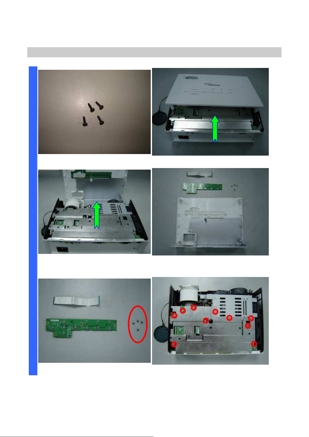
Removing the Top Cover and Keypad Board
I
Look these four screws (
S03)
S
A
S
S
E
M
Remove the FFC cable and take off the
top case.
B
L
Y
. Look at the top case.
Keypad board / FCC cable / Screw
review.
Review the four screw (
Company Confidential Optoma___________________ Delta________________
28
S04).
Remove the 7+3 piece screws.
2008/09/17
Page 29
Delta Elec. Inc. ES520 & EX530 ver.02
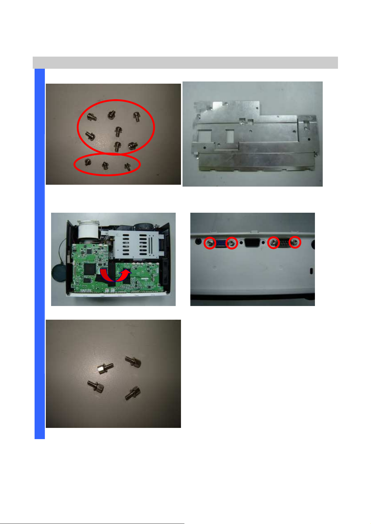
piece screws.
D
I
S
Review the 7
Removing the Main Board Plant & Main Board
(S05)+3(S06)
Remove the Main Board Plant.
A
S
S
E
M
B
L
Y
(two kinds S05 & S06).
Remove the Main Board. Remove the four hexagonal screws.
Review four hexagonal screws (S07).
Company Confidential Optoma___________________ Delta________________
29
2008/09/17
Page 30
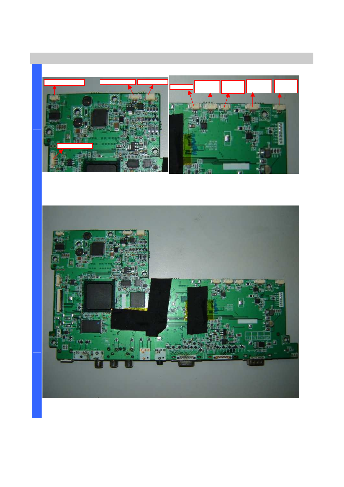
Delta Elec. Inc. ES520 & EX530 ver.02
check these right positions connection
area of these connectors and
check these right positions connection
D
CN300 SPK
-
Mono
Main Board Review
I
Careful area of these connectors and
S
when you recover main board again.
A
S
S
CN341
Blower Fan
CN343
Lock-SW
CN340
Power Fan
CN344
Lamp Fan
Careful
when you recover main board again.
E
M
B
L
Y
Main Board Review #Top side
Company Confidential Optoma___________________ Delta________________
30
2008/09/17
Page 31
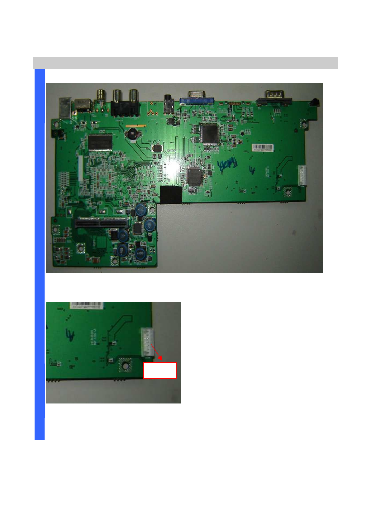
D
S
A
S
Delta Elec. Inc. ES520 & EX530 ver.02
Main Board Review
I
S
E
M
Main Board Review #Bottom side
B
L
Y
Connector CN900 to Key Pad board
CN900 to
Power Supply
Company Confidential Optoma___________________ Delta________________
31
2008/09/17
Page 32
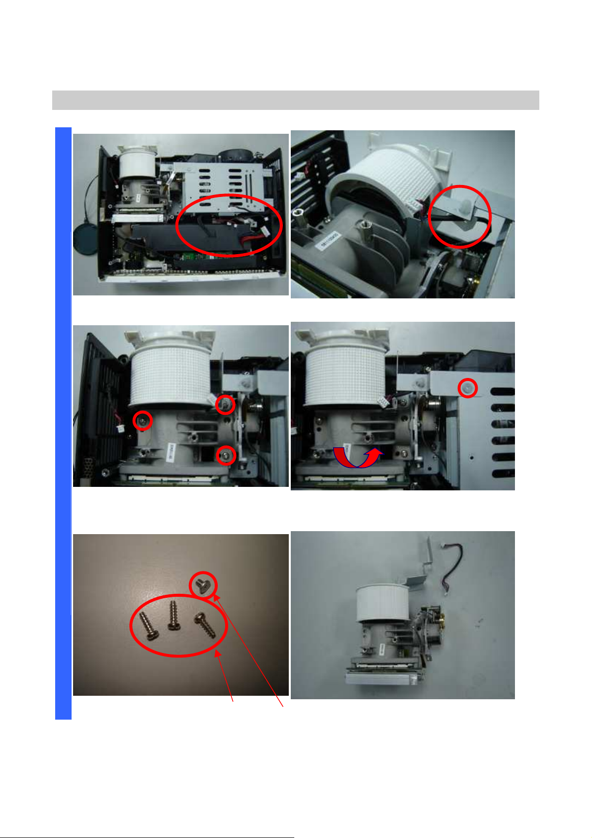
Delta Elec. Inc. ES520 & EX530 ver.02
D
Removing the Optical Engine
I
Careful assembly when you assemble it.
S
A
S
S
E
M
Remove the three screws. Remove the screw and take off the
B
L
Y
Careful assembly when you assemble it.
optical engine.
Review the screws (two kinds S08 & S09).
Company Confidential Optoma___________________ Delta________________
32
Review the optical engine.
2008/09/17
Page 33
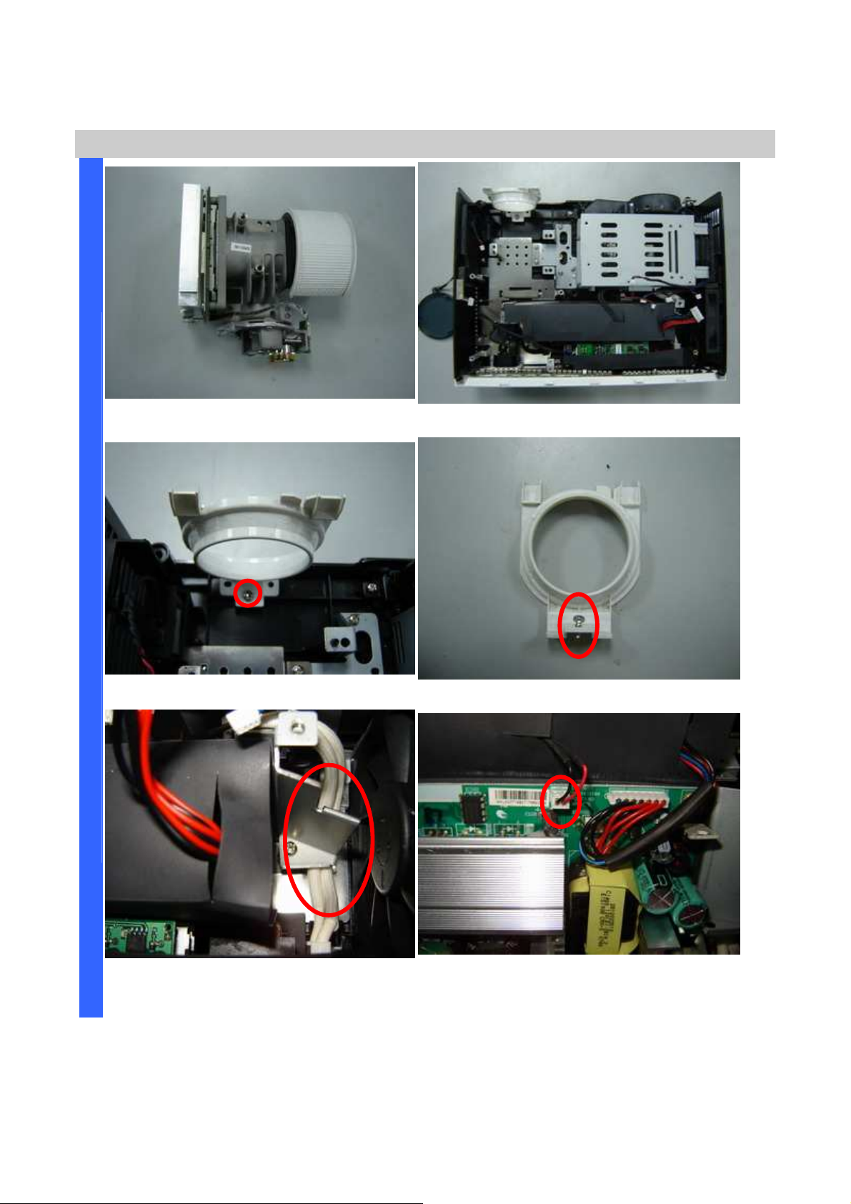
Delta Elec. Inc. ES520 & EX530 ver.02
D
the HV wire position when you
Removing the Optical engine and Power Supply
I
Review the optical engine (other side).
Review the bottom case w/o optical engine.
S
A
S
S
E
M
Remove the zoom ring screw (S10). Review the zoom ring and the screw.
B
L
Y
Careful
assemble it.
Company Confidential Optoma___________________ Delta________________
33
Remove the wire connector.
2008/09/17
Page 34
Delta Elec. Inc. ES520 & EX530 ver.02
D
Removing the Power Supply
I
S
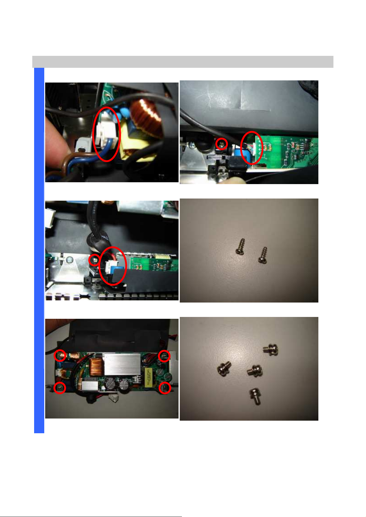
Remove the wire connector.
A
S
S
E
M
Remove the wire connector and screw.
B
L
Y
Remove the wire connector and screw.
Review these two screws (S11).
Remove the four screws. Review these four screws (S12).
Company Confidential Optoma___________________ Delta________________
34
2008/09/17
Page 35
Delta Elec. Inc. ES520 & EX530 ver.02
D
Removing the Ballast Board
I
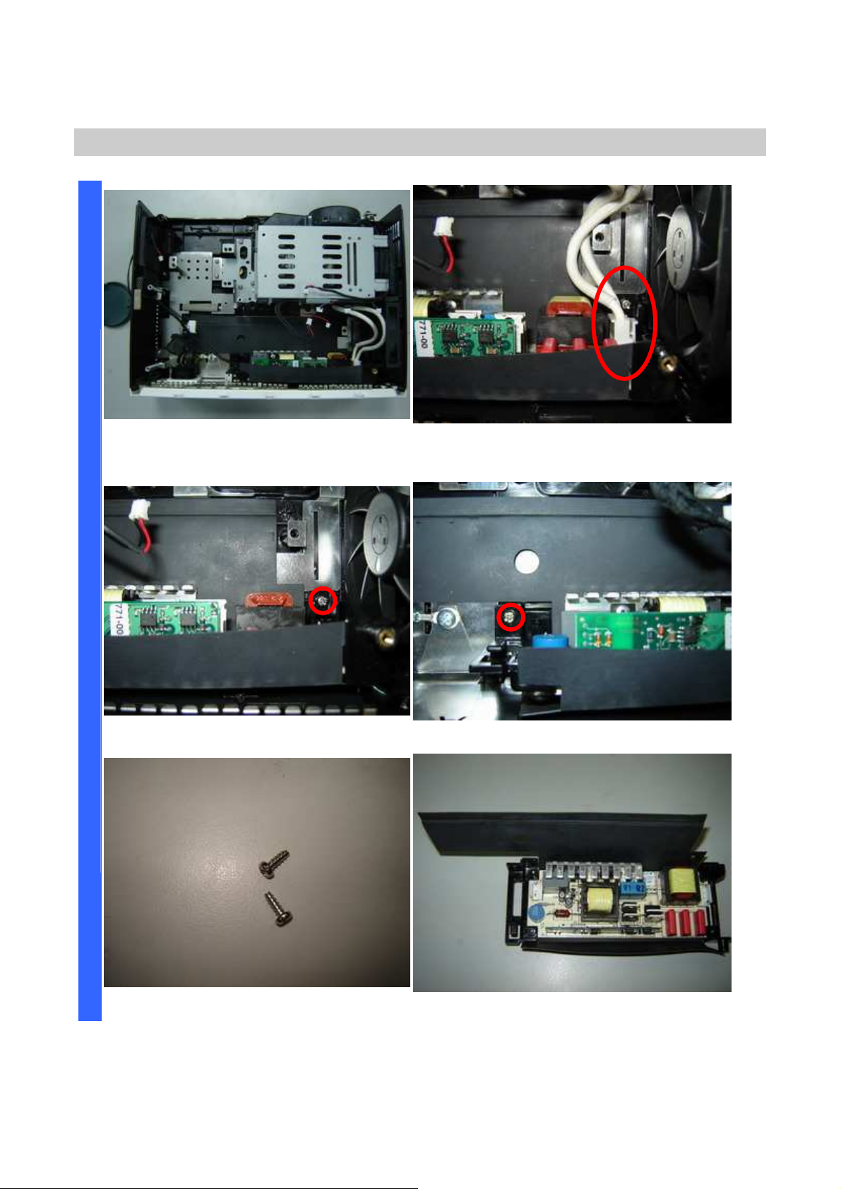
Review the bottom case w/o Power
S
board.
A
S
S
E
M
B
Remove the screw 1 of 2. Remove the screw 2 of 2.
L
Y
Remove the HV wire.
Review the two screws (S13).
Company Confidential Optoma___________________ Delta________________
35
Review the top side of Ballast with film.
2008/09/17
Page 36
Delta Elec. Inc. ES520 & EX530 ver.02
D
Removing the Ballast & Fan & IR sensor board
I
S
A
S
S
E
M
B
L
Y
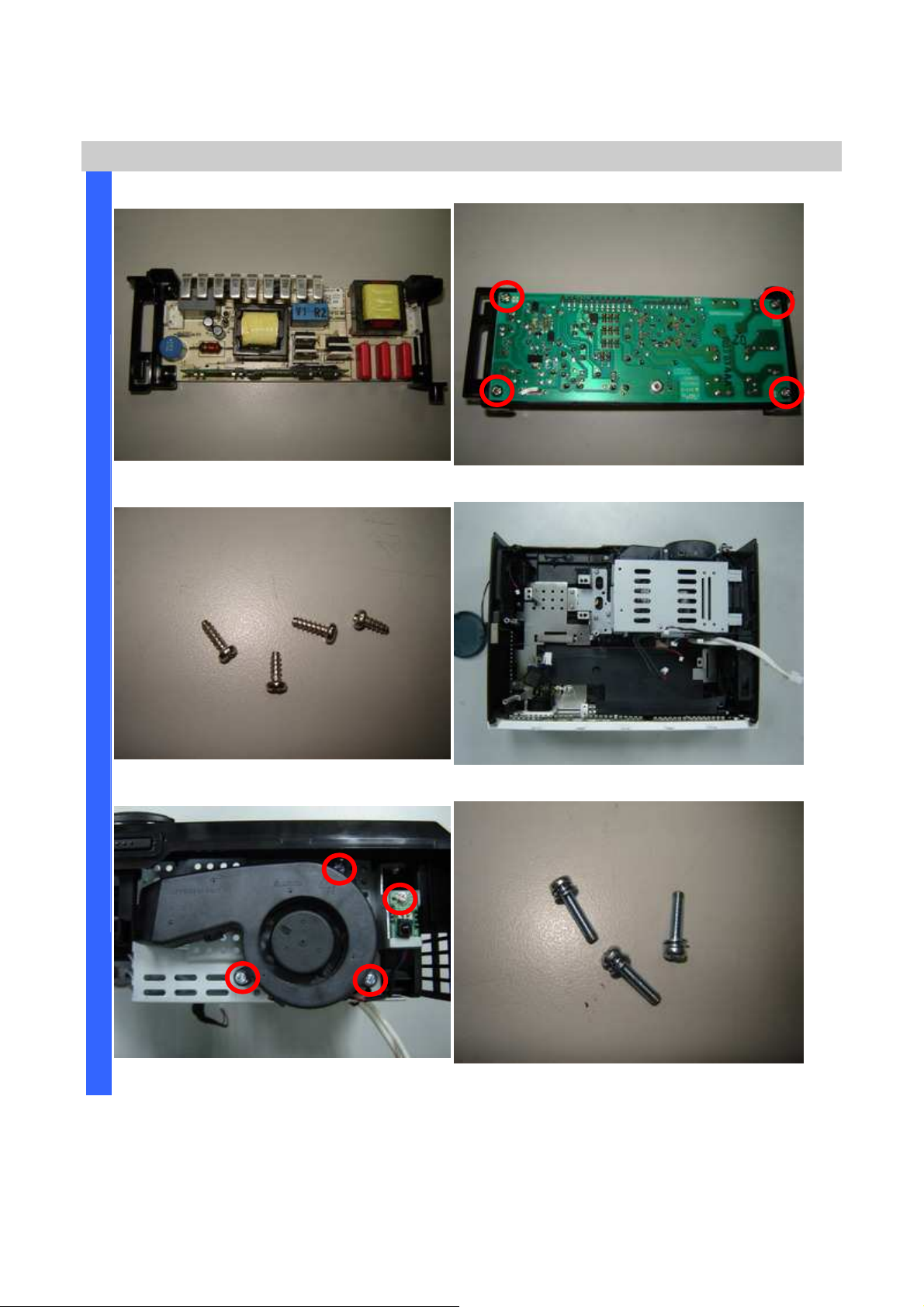
Review the top side of Ballast. Remove the four screws.
Review the four screws (S14). Review the bottom side w/o Ballast.
Remove the four screw. Review the three screws (S15).
Company Confidential Optoma___________________ Delta________________
36
2008/09/17
Page 37
Delta Elec. Inc. ES520 & EX530 ver.02
Removing the Lamp module chassis fan and accessory
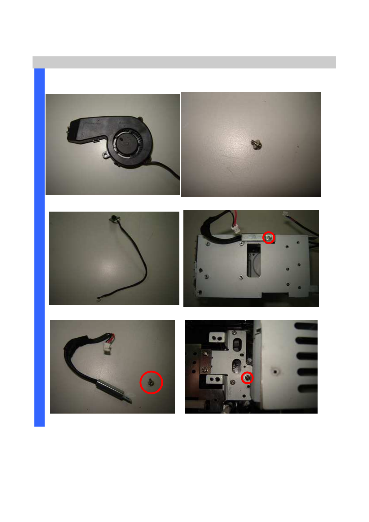
Review the lens fan. Review the screw (S16).
Remove the IR receiver board. Remove the thermal break.
Remove the thermal break and screw (S17).
Remove the screw (S18).
Company Confidential Optoma___________________ Delta________________
37
2008/09/17
Page 38
Delta Elec. Inc. ES520 & EX530 ver.02
D
Removing the Lamp module chassis
I
S
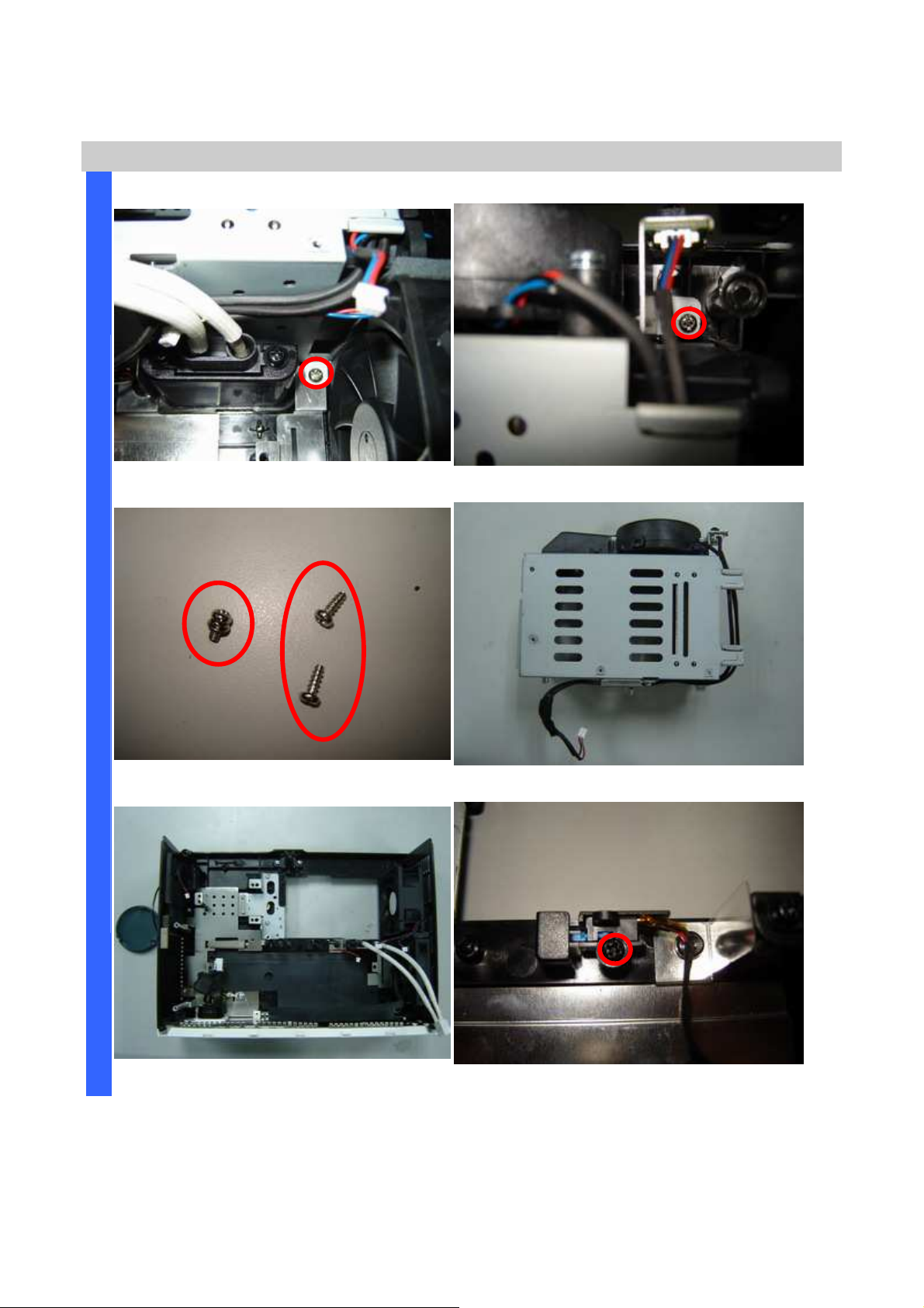
Remove the screw 1 of 2 (S19). Remove the other screw 2 of 2 (S19).
A
S
S
E
M
Review the three screws (two kinds).
B
L
Y
Remove the Lamp module chassis.
Review the bottom side w/o Lamp chassis. Remove interlock switch (one screw-S20).
Company Confidential Optoma___________________ Delta________________
38
2008/09/17
Page 39
Delta Elec. Inc. ES520 & EX530 ver.02
D
Removing the Accessory and Fans position review
I
S
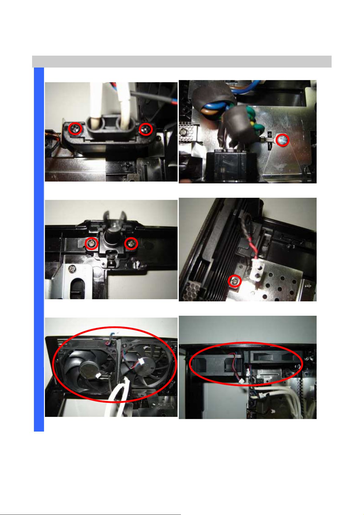
Remove the HV wire (two screws-S21). Remove grounding wire(one screw-S22).
A
S
S
E
M
Review the Adj foot (two screws-S23). Review the Spaker (one screw-S24).
B
L
Y
Careful the Fans position when you assemble it.
Company Confidential Optoma___________________ Delta________________
39
Careful the Fans position when you assemble it.
2008/09/17
Page 40
Delta Elec. Inc. ES520 & EX530 ver.02
D
Removing the Fans
I
S
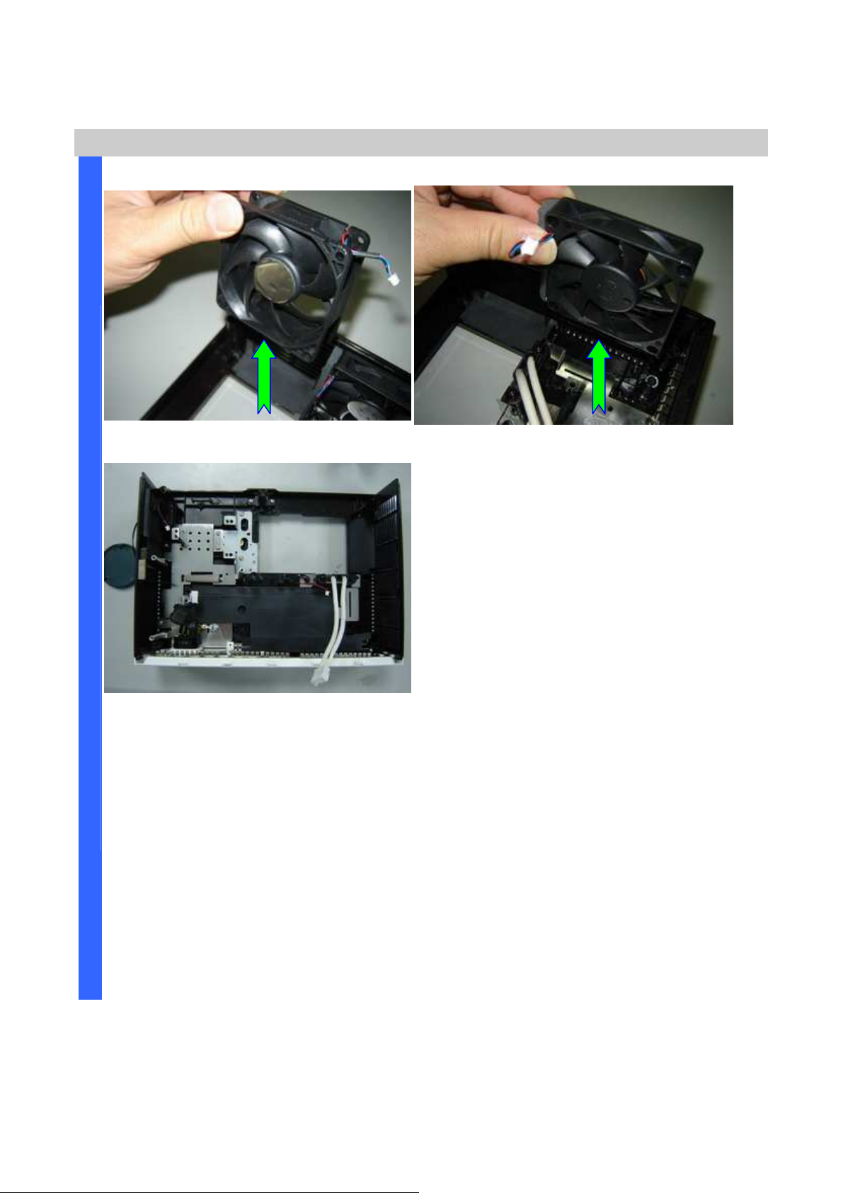
Remove the Fan #1. Remove the Fan #2.
A
S
S
E
M
Review the Bottom case assembly.
B
L
Y
Company Confidential Optoma___________________ Delta________________
40
2008/09/17
Page 41
Delta Elec. Inc. ES520 & EX530 ver.02
D
b. EX530 (DP-3511)
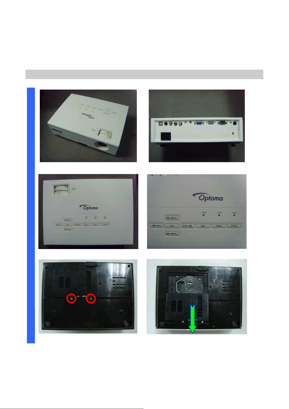
Removing the Lamp Cover and Lamp Module
I
S
A
S
S
E
M
B
L
Y
Look the full set projector. Look at the IO side.
Look at the case of top side. Look at the keypad of top side.
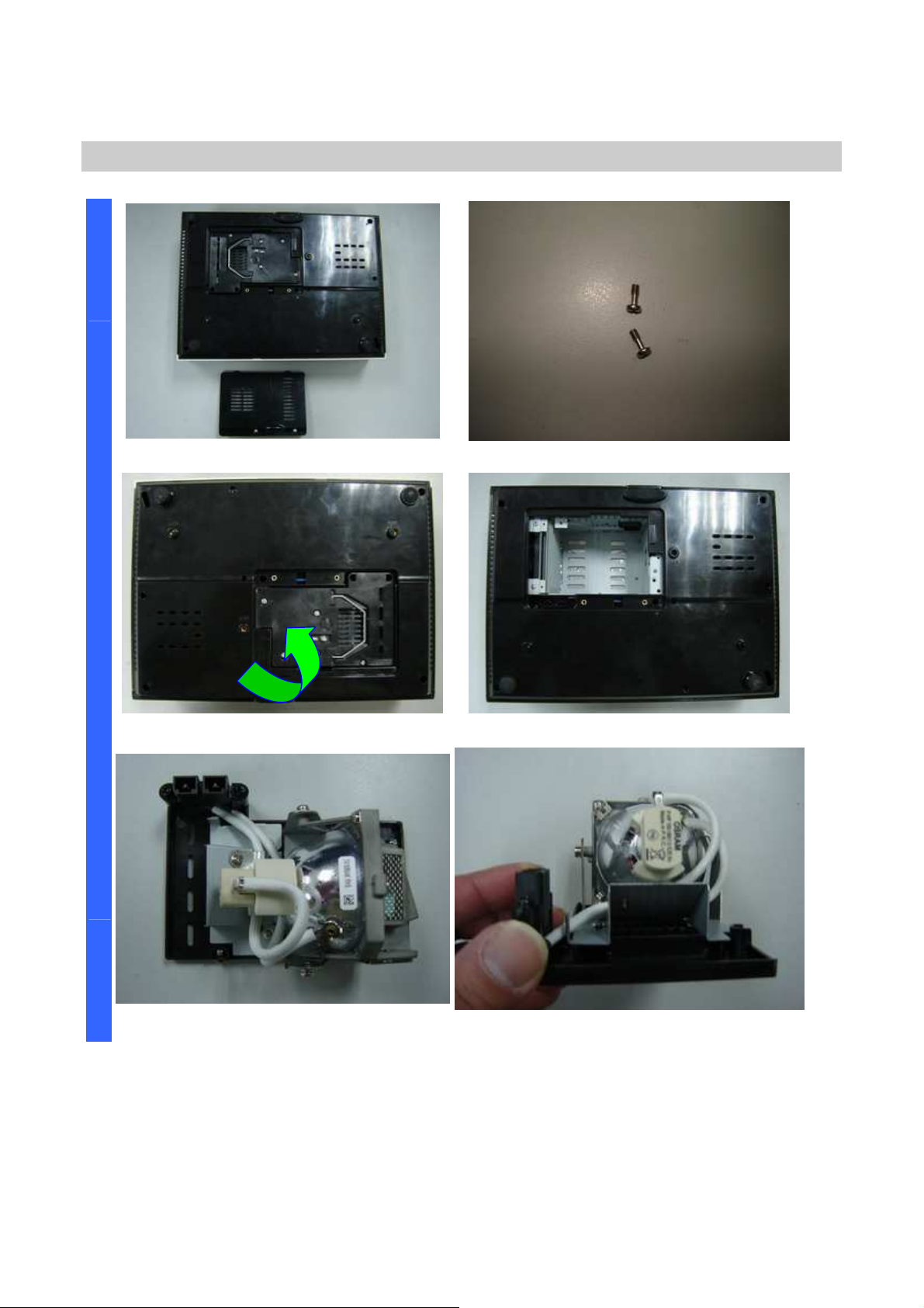
Loose these two screws. Remove and take out the lamp cover.
Company Confidential Optoma___________________ Delta________________
41
2008/09/17
Page 42
Delta Elec. Inc. ES520 & EX530 ver.02
D
Removing the Lamp Cover and Lamp Module
I
S
A
S
Remove the lamp cover. Loose two screws and take out (S01).
S
E
M
B
L
Y
Remove the lamp modules. Look the bottom case.
Look the Lamp #1.
Look the Lamp #2.
Company Confidential Optoma___________________ Delta________________
42
2008/09/17
Page 43
Delta Elec. Inc. ES520 & EX530 ver.02
D
Removing the Lamp Module and Top Cover
I
S
A
S
S
E
M
B
L
Y
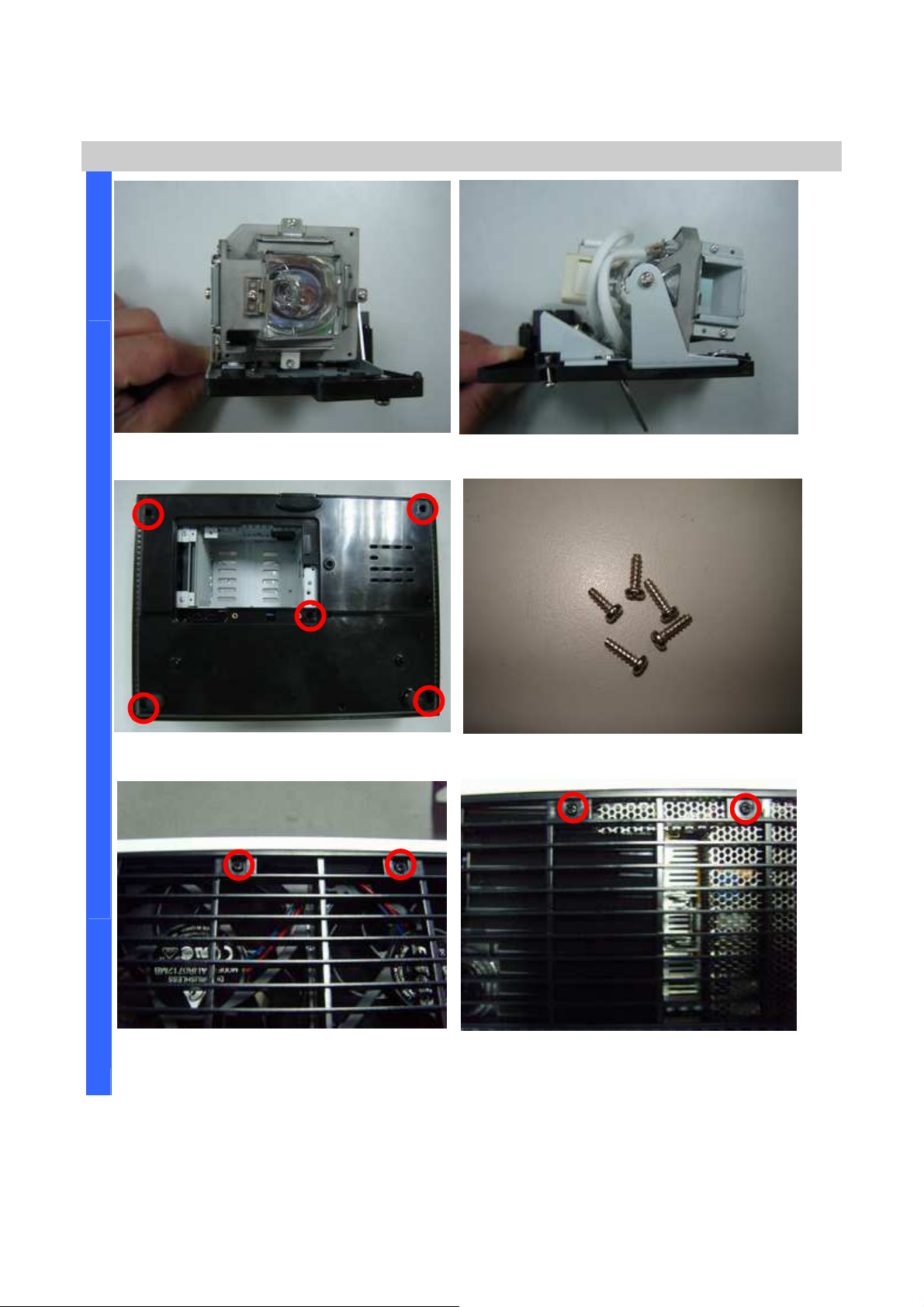
Look the Lamp #3. Look the Lamp #4.
Remove the five screws. Look these five screws (
S02)
.
Remove the two screws.
Company Confidential Optoma___________________ Delta________________
43
Remove the two screws.
2008/09/17
Page 44
Delta Elec. Inc. ES520 & EX530 ver.02
D
Removing the Top Cover and Keypad Board
I
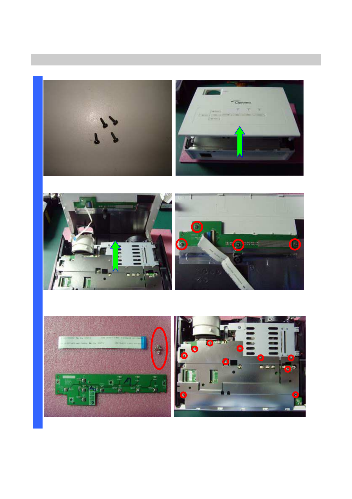
Look these four screws (
S03)
S
A
S
S
E
M
Remove the FFC cable and take off the
top case.
B
L
Y
. Look at the top case.
Remove the four screws.
Review the four screw (
Company Confidential Optoma___________________ Delta________________
44
S04).
Remove the 7+3 piece screws.
2008/09/17
Page 45
Delta Elec. Inc. ES520 & EX530 ver.02
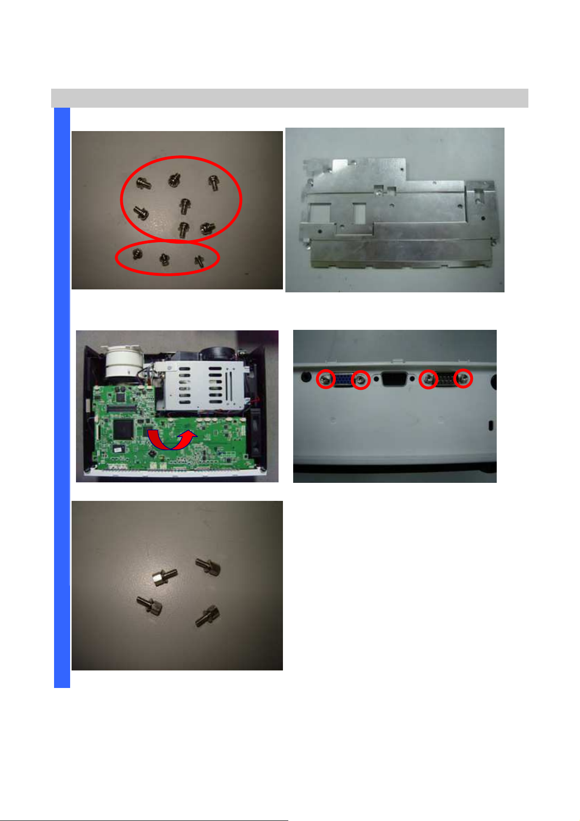
piece screws.
D
I
S
Review the 7
Removing the Main Board Plant & Main Board
(S05)+3(S06)
Remove the Main Board Plant.
A
S
S
E
M
B
L
Y
(two kinds S05 & S06).
Remove the Main Board. Remove the four hexagonal screws.
Review four hexagonal screws (S07).
Company Confidential Optoma___________________ Delta________________
45
2008/09/17
Page 46
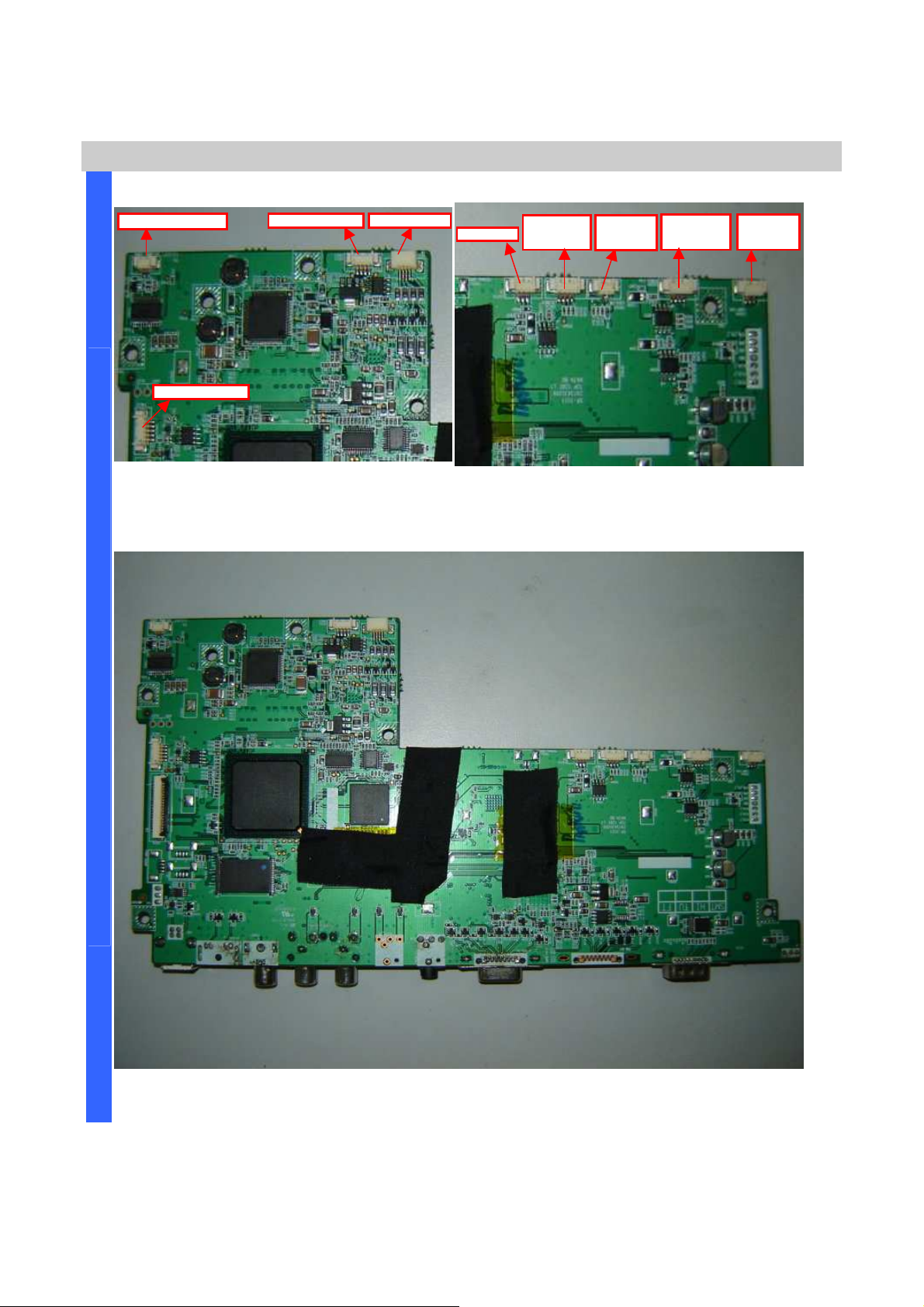
Delta Elec. Inc. ES520 & EX530 ver.02
check these right positions connection
nd
check these right positions connection
D
CN300 SPK
-
Mono
Main Board Review
I
Careful area of these connectors and
S
when you recover main board again.
A
S
S
CN341
Blower Fan
CN343
Lock-SW
CN340
Power Fan
CN344
Lamp Fan
Careful area of these connectors a
when you recover main board again.
E
M
B
L
Y
Main Board Review #Top side
Company Confidential Optoma___________________ Delta________________
46
2008/09/17
Page 47
D
S
A
S
Delta Elec. Inc. ES520 & EX530 ver.02
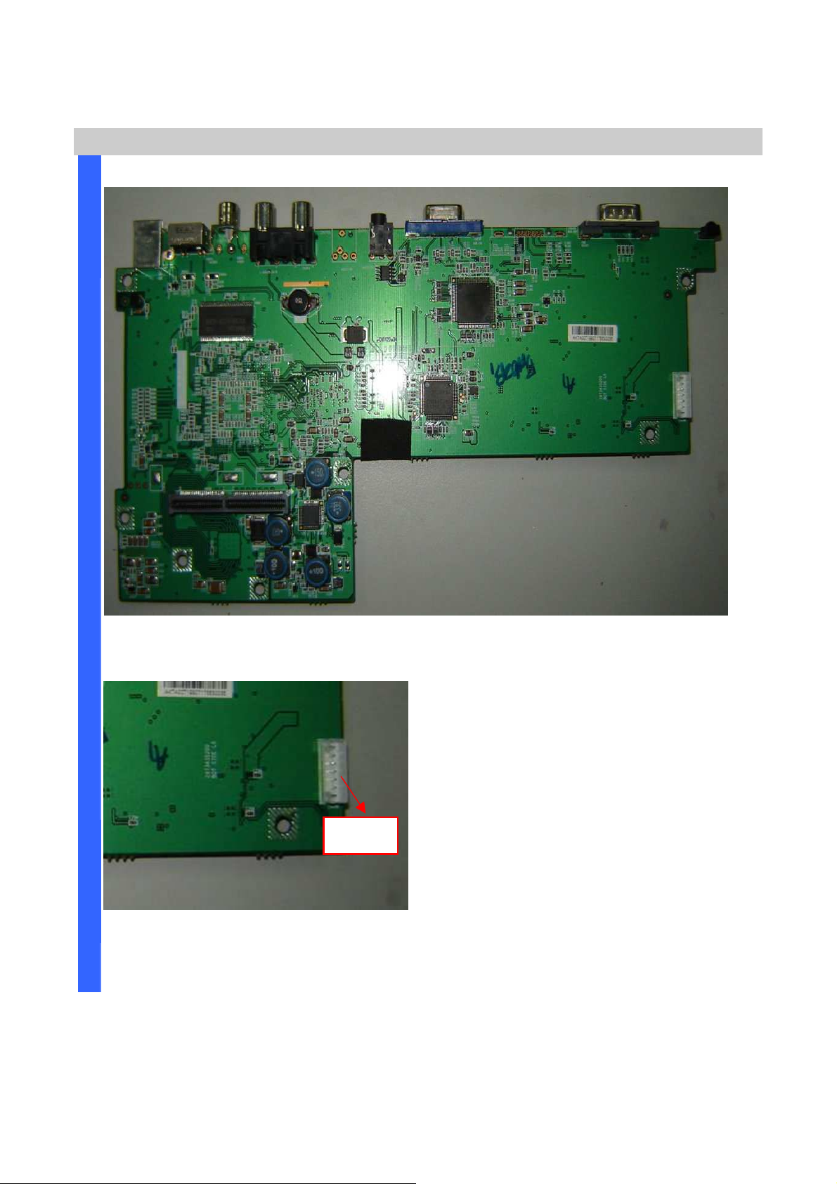
Main Board Review
I
S
E
M
Main Board Review #Bottom side
B
L
Y
Connector CN900 to Key Pad board
CN900 to
Power Supply
Company Confidential Optoma___________________ Delta________________
47
2008/09/17
Page 48
Delta Elec. Inc. ES520 & EX530 ver.02
D
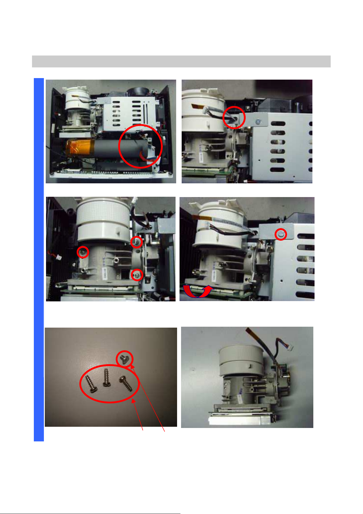
Removing the Optical Engine
I
Careful assembly when you assemble it.
S
A
S
S
E
M
Remove the three screws. Remove the screw and take off the
B
L
Y
Careful assembly when you assemble it.
optical engine.
Review the screws (two kinds S08 & S09).
Company Confidential Optoma___________________ Delta________________
48
Review the optical engine.
2008/09/17
Page 49
Delta Elec. Inc. ES520 & EX530 ver.02
D
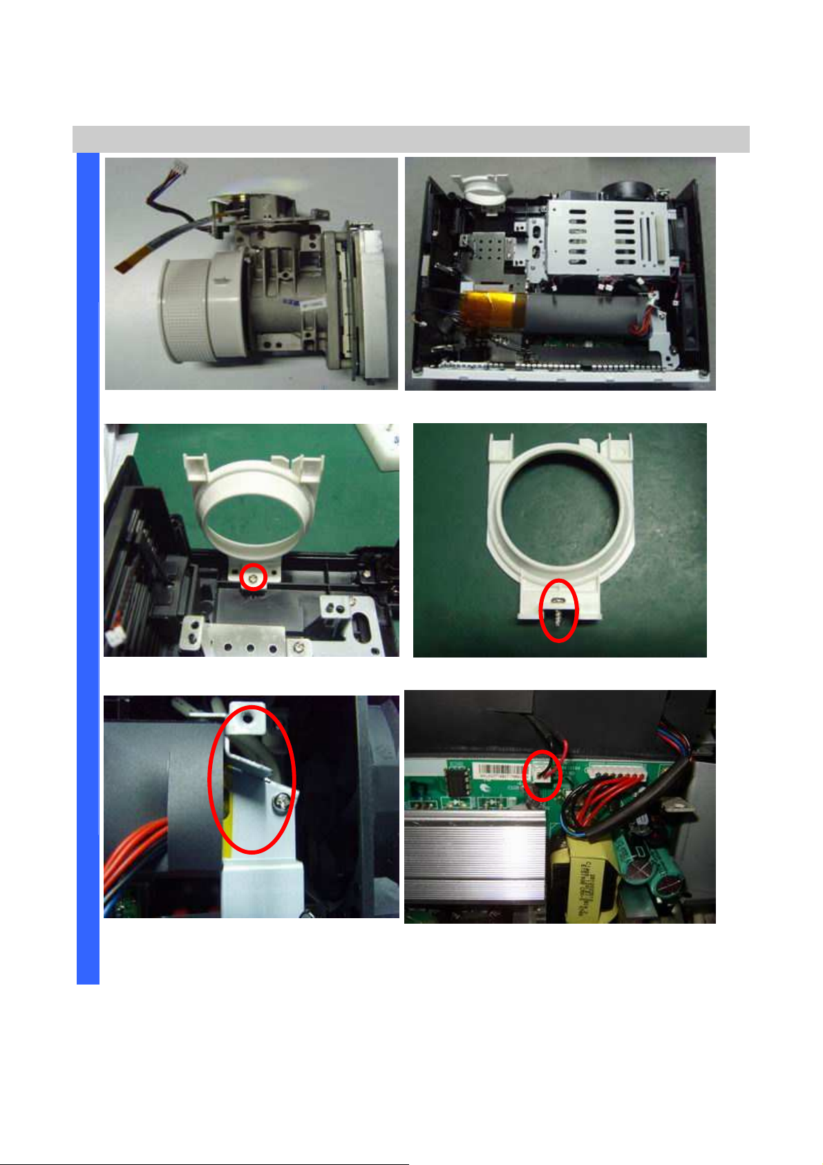
the HV wire position when you
Removing the Optical engine and Power Supply
I
Review the optical engine (other side).
Review the bottom case w/o optical engine.
S
A
S
S
E
M
Remove the zoom ring screw (S10). Review the zoom ring and the screw.
B
L
Y
Careful
assemble it.
Company Confidential Optoma___________________ Delta________________
49
Remove the wire connector.
2008/09/17
Page 50
Delta Elec. Inc. ES520 & EX530 ver.02
D
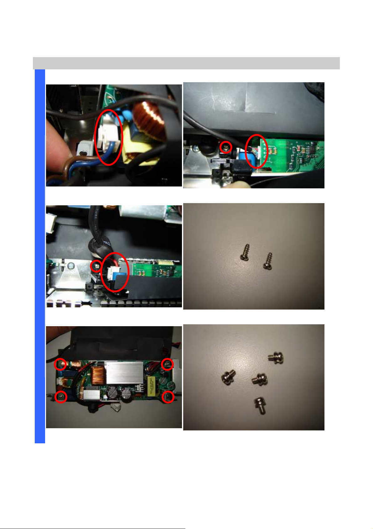
Removing the Power Supply
I
S
Remove the wire connector.
A
S
S
E
M
Remove the wire connector and screw.
B
L
Y
Remove the wire connector and screw.
Review these two screws (S11).
Remove the four screws. Review these four screws (S12).
Company Confidential Optoma___________________ Delta________________
50
2008/09/17
Page 51
Delta Elec. Inc. ES520 & EX530 ver.02
D
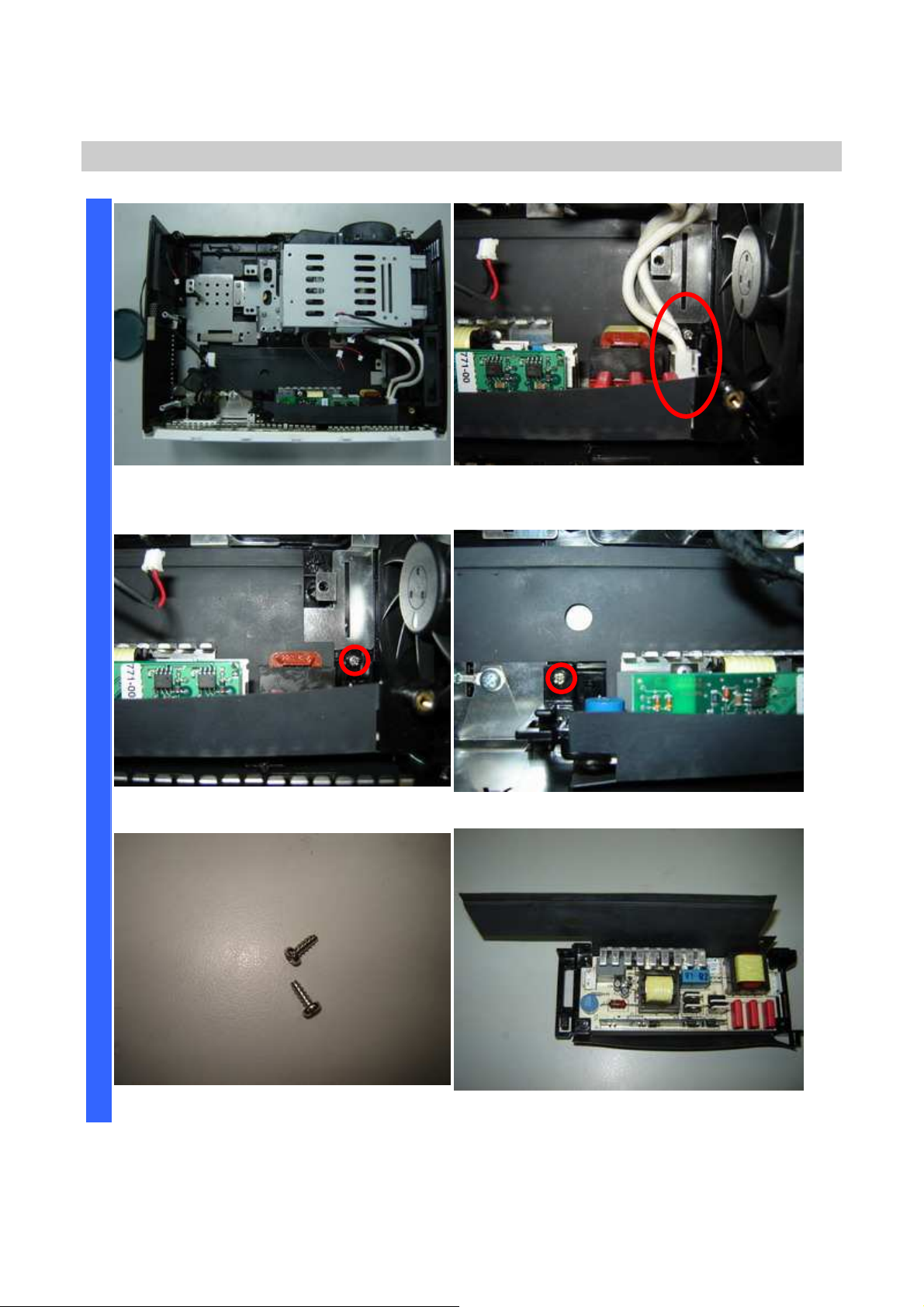
Removing the Ballast Board
I
Review the bottom case w/o Power
S
board.
A
S
S
E
M
B
Remove the screw 1 of 2. Remove the screw 2 of 2.
L
Y
Remove the HV wire.
Review the two screws (S13).
Company Confidential Optoma___________________ Delta________________
51
Review the top side of Ballast with film.
2008/09/17
Page 52
Delta Elec. Inc. ES520 & EX530 ver.02
D
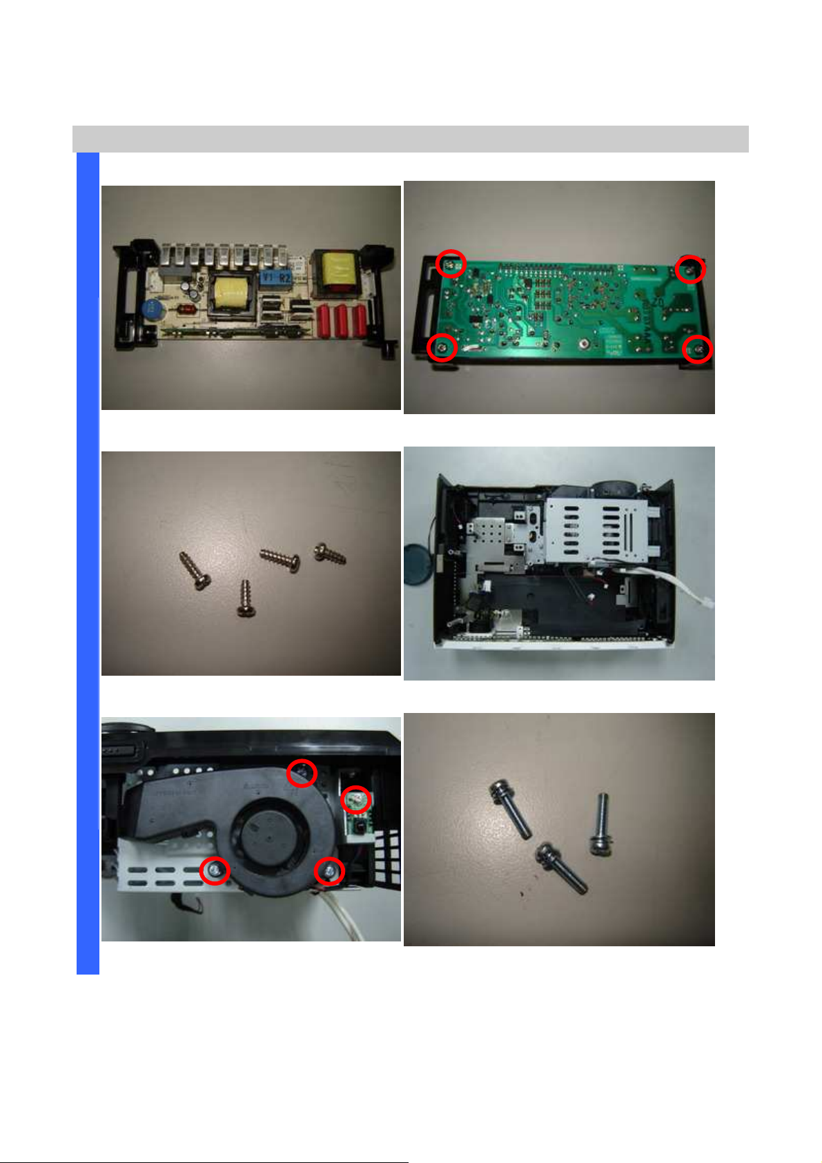
Removing the Ballast & Fan & IR sensor board
I
S
A
S
S
E
M
B
L
Y
Review the top side of Ballast. Remove the four screws.
Review the four screws (S14). Review the bottom side w/o Ballast.
Remove the four screw. Review the three screws (S15).
Company Confidential Optoma___________________ Delta________________
52
2008/09/17
Page 53
Delta Elec. Inc. ES520 & EX530 ver.02
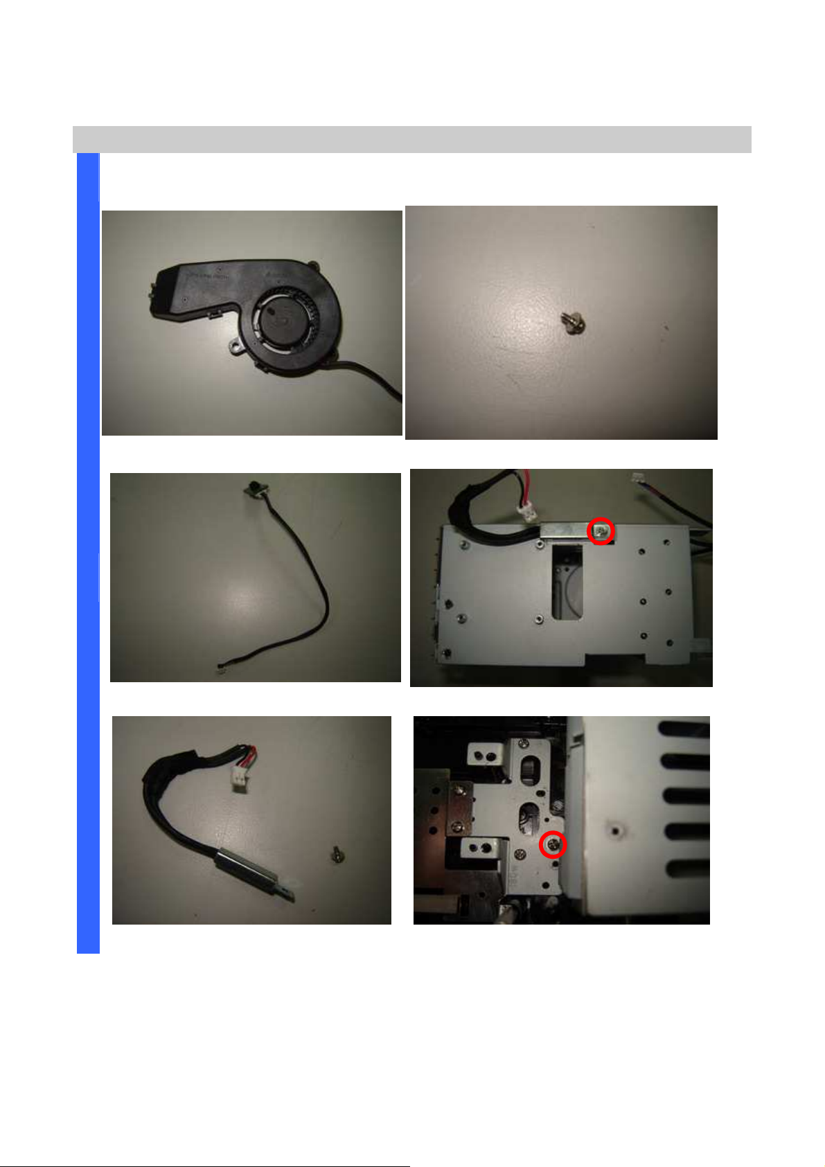
Removing the Lamp module chassis fan and accessory
Review the lens fan. Review the screw (S16).
Remove the IR receiver board. Remove the thermal break.
Remove the thermal break and screw (S17).
Remove the screw (S18).
Company Confidential Optoma___________________ Delta________________
53
2008/09/17
Page 54
Delta Elec. Inc. ES520 & EX530 ver.02
D
Removing the Lamp module chassis
I
S
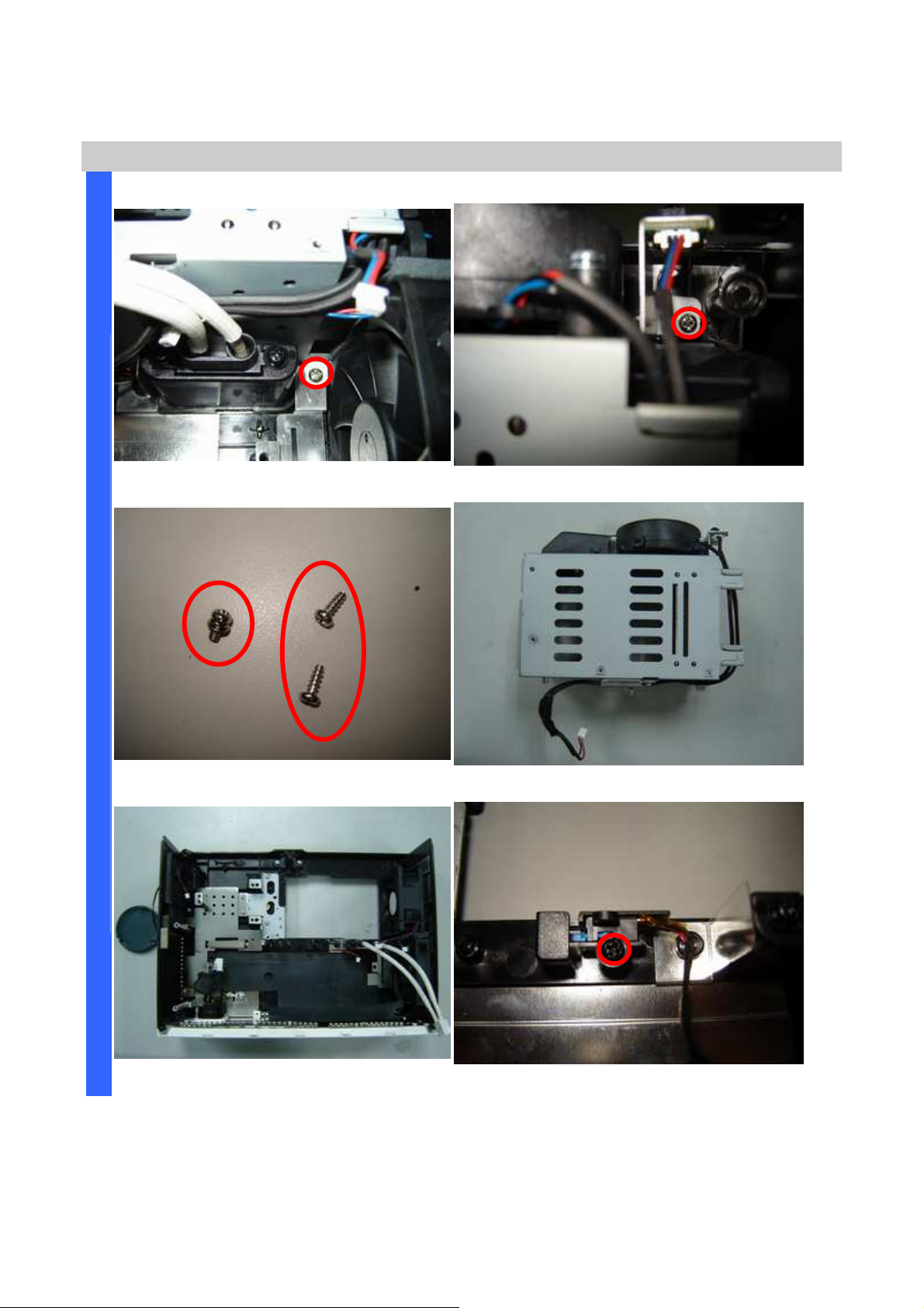
Remove the screw 1 of 2 (S19). Remove the other screw 2 of 2 (S19).
A
S
S
E
M
Review the three screws (two kinds).
B
L
Y
Remove the Lamp module chassis.
Review the bottom side w/o Lamp chassis. Remove interlock switch (one screw-S20).
Company Confidential Optoma___________________ Delta________________
54
2008/09/17
Page 55
Delta Elec. Inc. ES520 & EX530 ver.02
D
Removing the Accessory and Fans position review
I
S
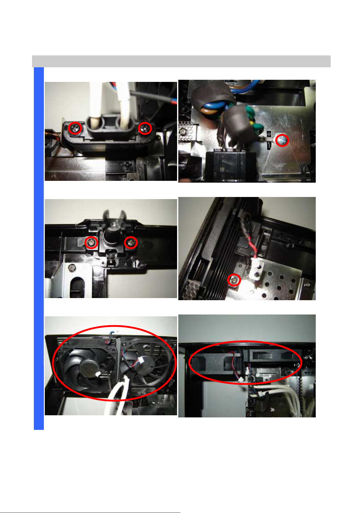
Remove the HV wire (two screws-S21). Remove grounding wire(one screw-S22).
A
S
S
E
M
Review the Adj foot (two screws-S23). Review the Spaker (one screw-S24).
B
L
Y
Careful the Fans position when you assemble it.
Company Confidential Optoma___________________ Delta________________
55
Careful the Fans position when you assemble it.
2008/09/17
Page 56
Delta Elec. Inc. ES520 & EX530 ver.02
D
Removing the Fans
I
S
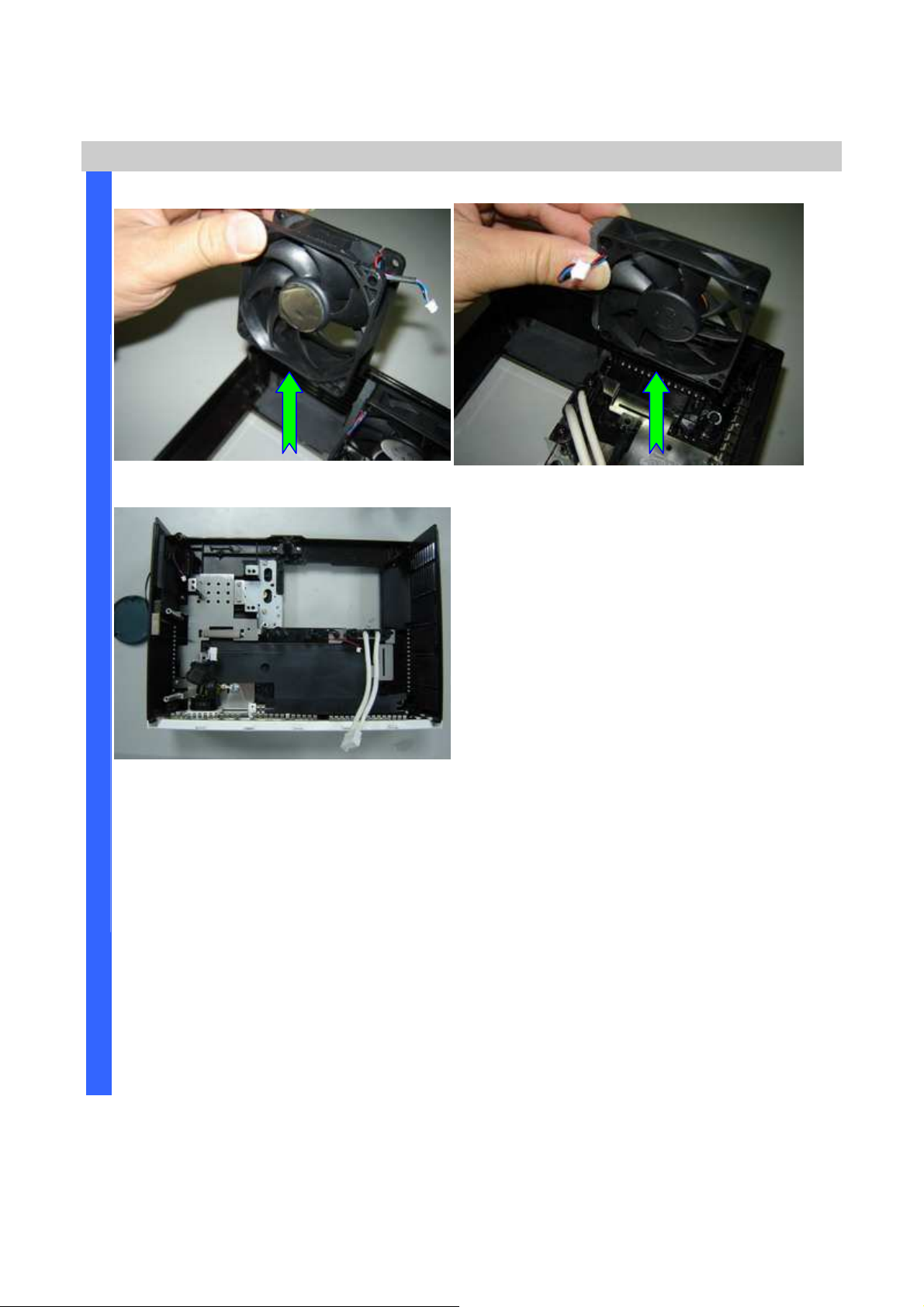
Remove the Fan #1. Remove the Fan #2.
A
S
S
E
M
Review the Bottom case assembly.
B
L
Y
Company Confidential Optoma___________________ Delta________________
56
2008/09/17
Page 57

Delta Elec. Inc. ES520 & EX530 ver.02
Appendix. Screw torque
item-S Screw Type P/N
1 M3*0.5*10
2
φ
φ3*1.27*10
φφ
3
φφφφ2*0.8*5
4 M2*0.4*5
5 M3*0.5*6
6 M2*0.4*5
7 M #4-40*7 L12
8
3*1.27*10
φφφφ
9 M3*0.5*6
10
φ
φ3*1.06*8
φφ
11
3*1.06*8
φφφφ
12 M3*0.5*6
13
φ
φ3*1.06*8
φφ
14
φ
φ3*1.06*8
φφ
15 M3*0.5*14
16 M2*0.4*5
17 M2*0.4*5
18
19
3*1.06*8
φφφφ
3*1.06*8
φφφφ
20 φφφφ3*1.06*8
21 φφφφ3*1.06*8
22 M4*0.7*4
23 φφφφ3*1.06*8
24 φφφφ3*1.06*8
3105320500
3109015300
3109101800
3105270500
3100320600
3105270500
3461431703
3109015300
3105039100
3106160400
3106160400
3100320600
3106160400
3106160400
3100301400
3105270500
3105270500
3106160400
3106160400
3106390400
3106390400
3102210601
3106390400
3106390400
4~5
4~5
2~3
1.8~2.2
4~5
1.5~2.0
4~5
4~5
2~3
4~5
4~5
4~5
4~5
4~5
4~5
1.5~2.0
1.5~2.0
4~5
4~5
4~5
4~5
4~5
4~5
4~5
Company Confidential Optoma___________________ Delta________________
57
2008/09/17
Page 58

Delta Elec. Inc. ES520 & EX530 ver.02
5. Flash Upgrade Flow
5-1.
Projector USB Drivers Installation Guide
Ver 6.0.0.4
The document is to describe a Windows application software “Flash-Tool” for projector firmware. Its main
purpose is to provide a detailed procedure of upgrading the application software of a DLP projector. The system
requirement and the installation procedure of “Flash-Tool” are also included in the document.
NOTE:
User must have administrative privileges on the target computer in order to
install the driver. (The installation target directory must not be write-protected.)
User also required having the basic knowledge of Windows application installation.
Attention: This utility is for DLPTM DDP2000/2230 series projectors only.
System Requirement
IBM compatible PC.
Windows XP-SP2 operating system.
Install Flash-Tool to PC
Run the “Digital Zoom Projector Flash Tool Vx.y.msi”, that will automatically launch the USB drivers update. The
following pictures are illustrating the process of the USB Driver installation.
Start-up page:
Click on the “Next” button to continue
or
Click on the “Cancel” button to cancel the installation
Company Confidential Optoma___________________ Delta________________
58
2008/09/17
Page 59

Delta Elec. Inc. ES520 & EX530 ver.02
Driver Destination:
Ready to Install:
Click on the “Change” button to change
the default directory for saving the driver
file somewhere else.
or
Click on the “Back” button to return to the
previous page
or
Click on the “Cancel” button to cancel the
installation
Click on the “install” button to start the
driver installation.
Installation in Progress:
or
Click on the “Back” button to return to the
previous page
or
Click on the “Cancel” button to cancel the
installation
Please wait for the installation to complete.
Company Confidential Optoma___________________ Delta________________
59
2008/09/17
Page 60
Delta Elec. Inc. ES520 & EX530 ver.02
s
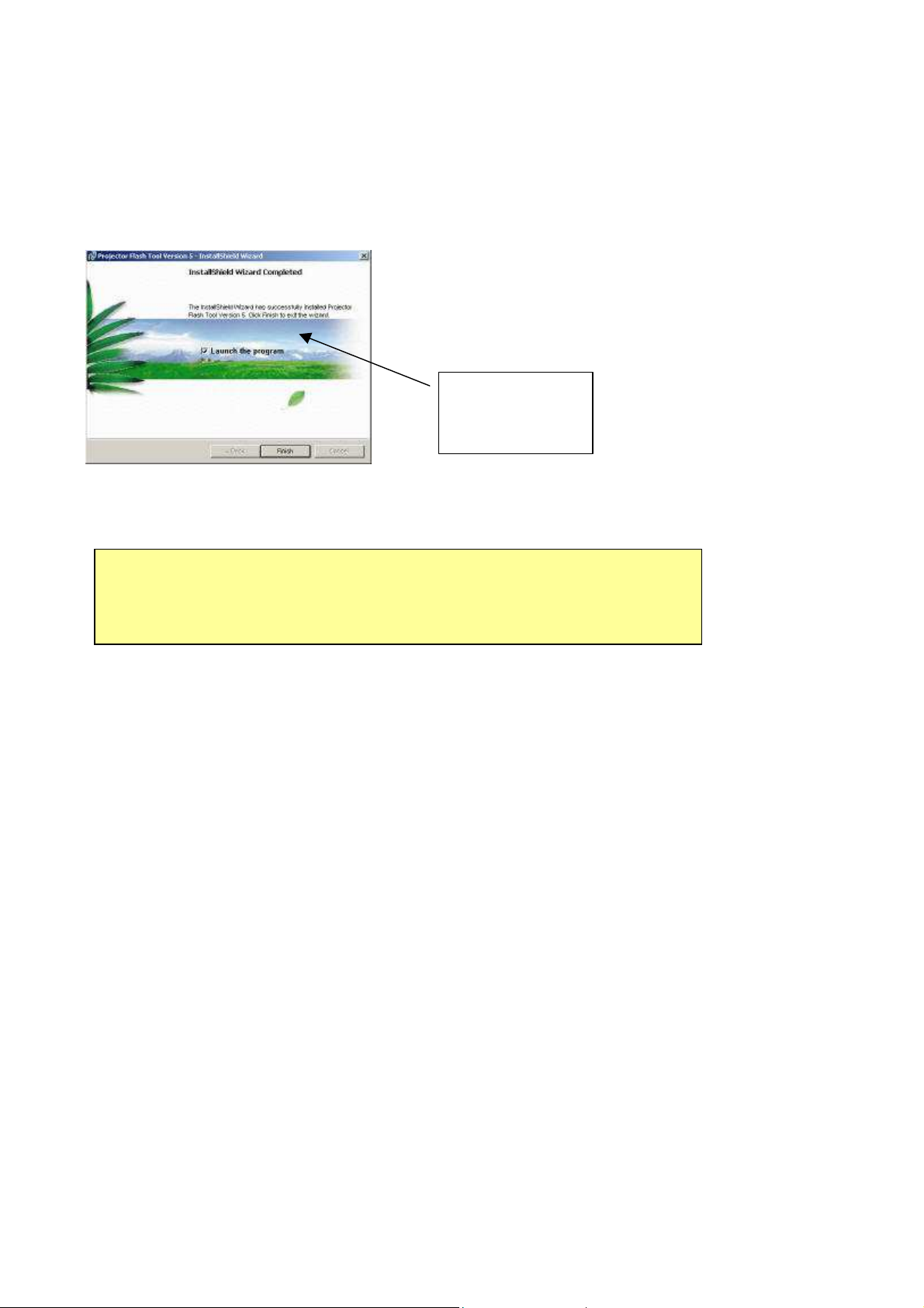
Installation Completed:
Click on the “Finish” button with the “Launch” checkbox
checked so that the Install Wizard will start the USB driver (INF
update.
Note: The USB driver (INF) update may take a few minutes depending your computer’
performance, and number of driver files. All dialogs will be automatically closed when
the installation is completed.
Launch the
driver update
Company Confidential Optoma___________________ Delta________________
60
2008/09/17
Page 61
Delta Elec. Inc. ES520 & EX530 ver.02
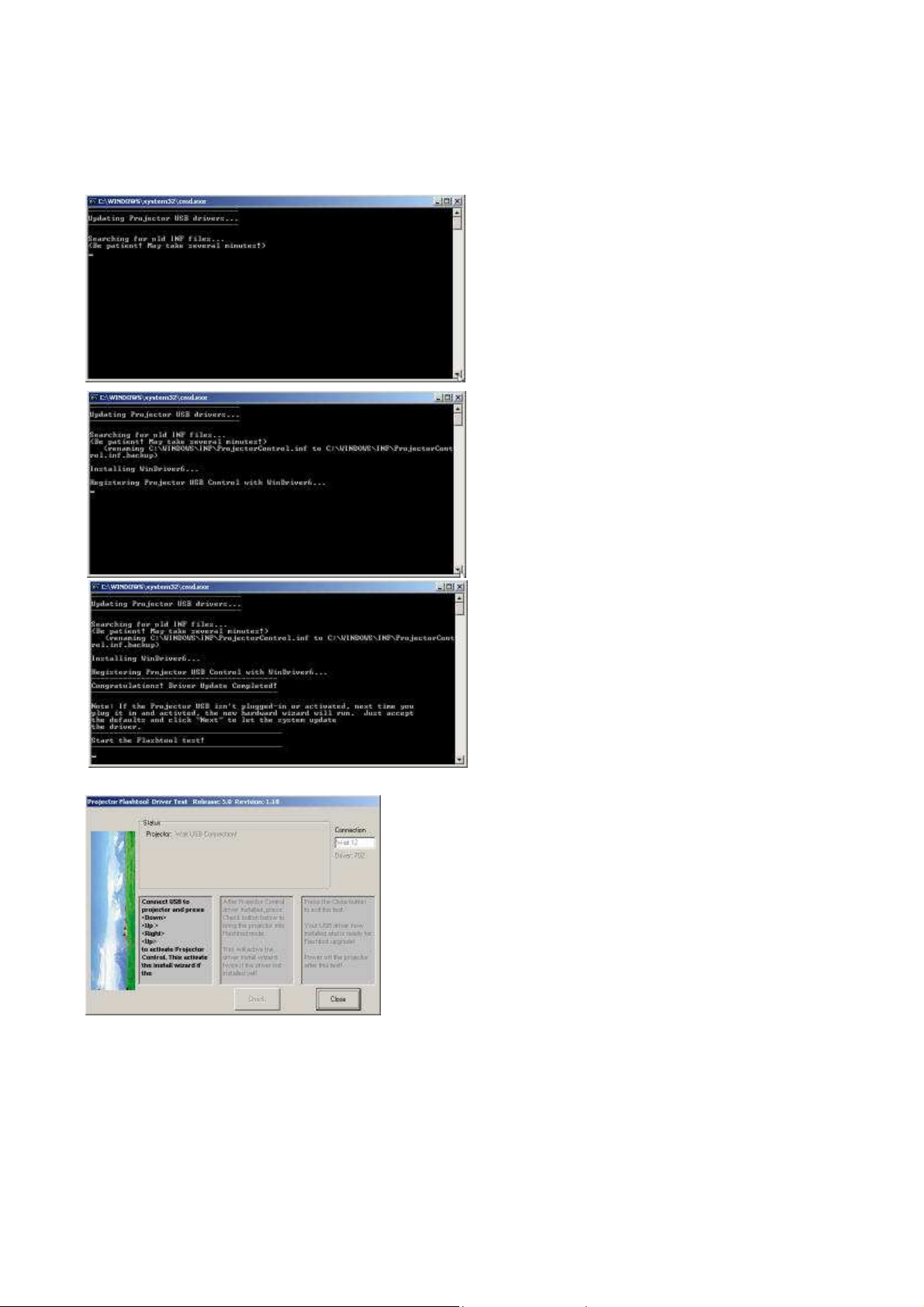
The Install Wizard is searching for the old driver files
to be replaced with the new ones.
Remove the USB cable between PC and
projector if it is connected.
The WinDrive USB drivers will be installed and
registered to the system.
When finished, a test application will execute
automatically with Windows hardware wizard for all
necessary USB drivers.
Connect the USB cable
If the driver test application does not launch automatically, run the
“Launch FlashToolBL.exe” from installed shortcut at
Program> Digital Zoom Projector> projector flashtool>
Launch FlasToolBL.exe
Company Confidential Optoma___________________ Delta________________
61
2008/09/17
Page 62
Delta Elec. Inc. ES520 & EX530 ver.02
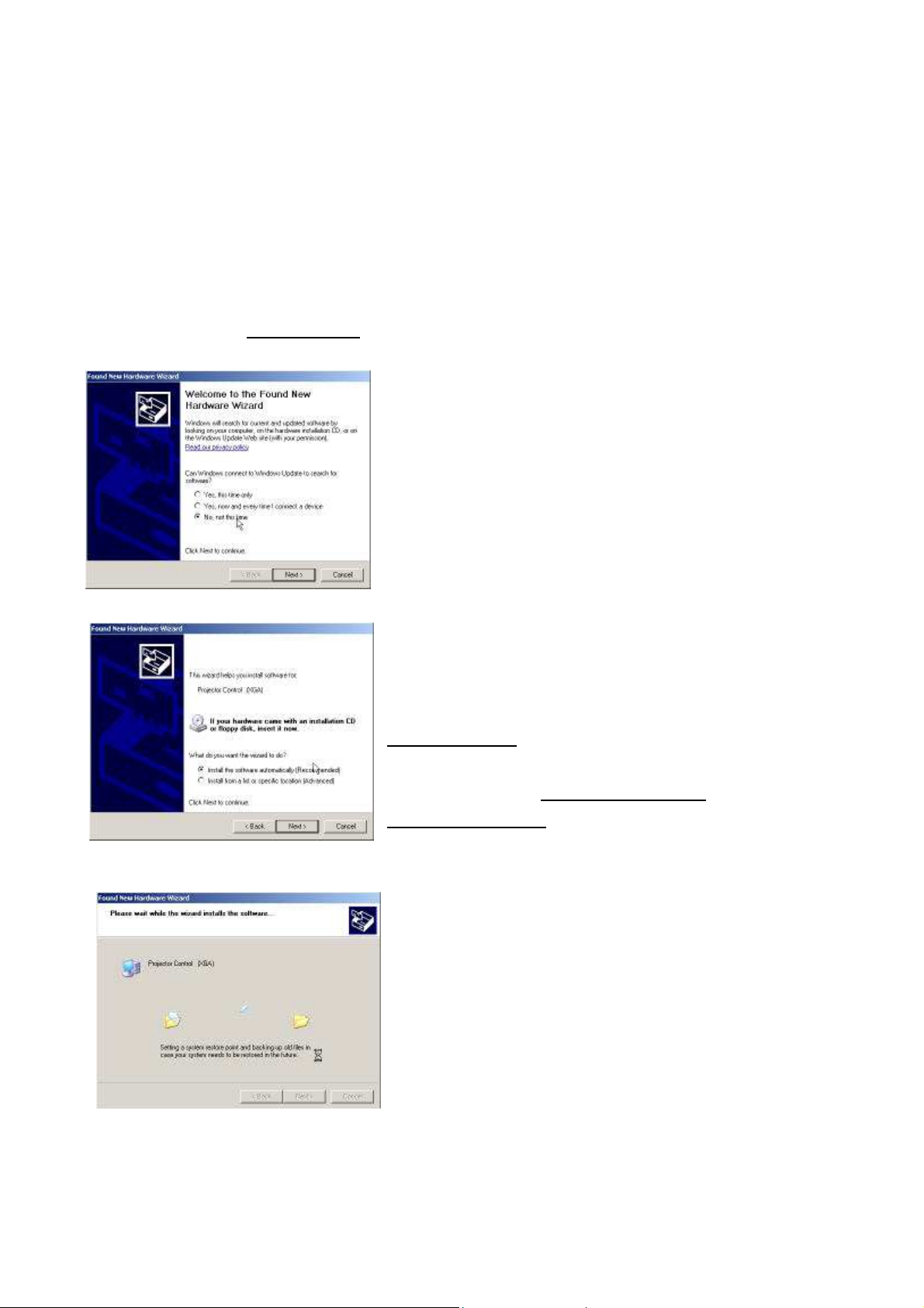
Connect the power cord to the projector, and move the power switch in its ON position (if
. The power and lamp LED
Make sure that the USB cable is firmly connected between projector and computer
available) so that projector is in the STAND-BY mode.
Press
<Down>, <Up>, <Right>, <Up>
using the IR remote controller for those with limited keypads
shall blink and the Projector Control mode will be enabled.
key in sequence using keypad buttons, or
The New Hardware Wizard launches for the first
time. Windows detects a new USB device
attached.
Select “No, not this time”
Click on the “Next” button to continue
(This dialog may change on different Windows
version)
Select “Install the software automatically”
Click on the “Next” button to continue
* In case the wizard cannot find the driver (the
ProjectorControl.inf), please select the other
advanced option and specify the driver location
manually. (Normally at
Projector\Projector Flash Tool
Windows updates the USB Projector Control
driver when found
C:\Program Files\Digital Zoom
)
Company Confidential Optoma___________________ Delta________________
62
2008/09/17
Page 63
Delta Elec. Inc. ES520 & EX530 ver.02
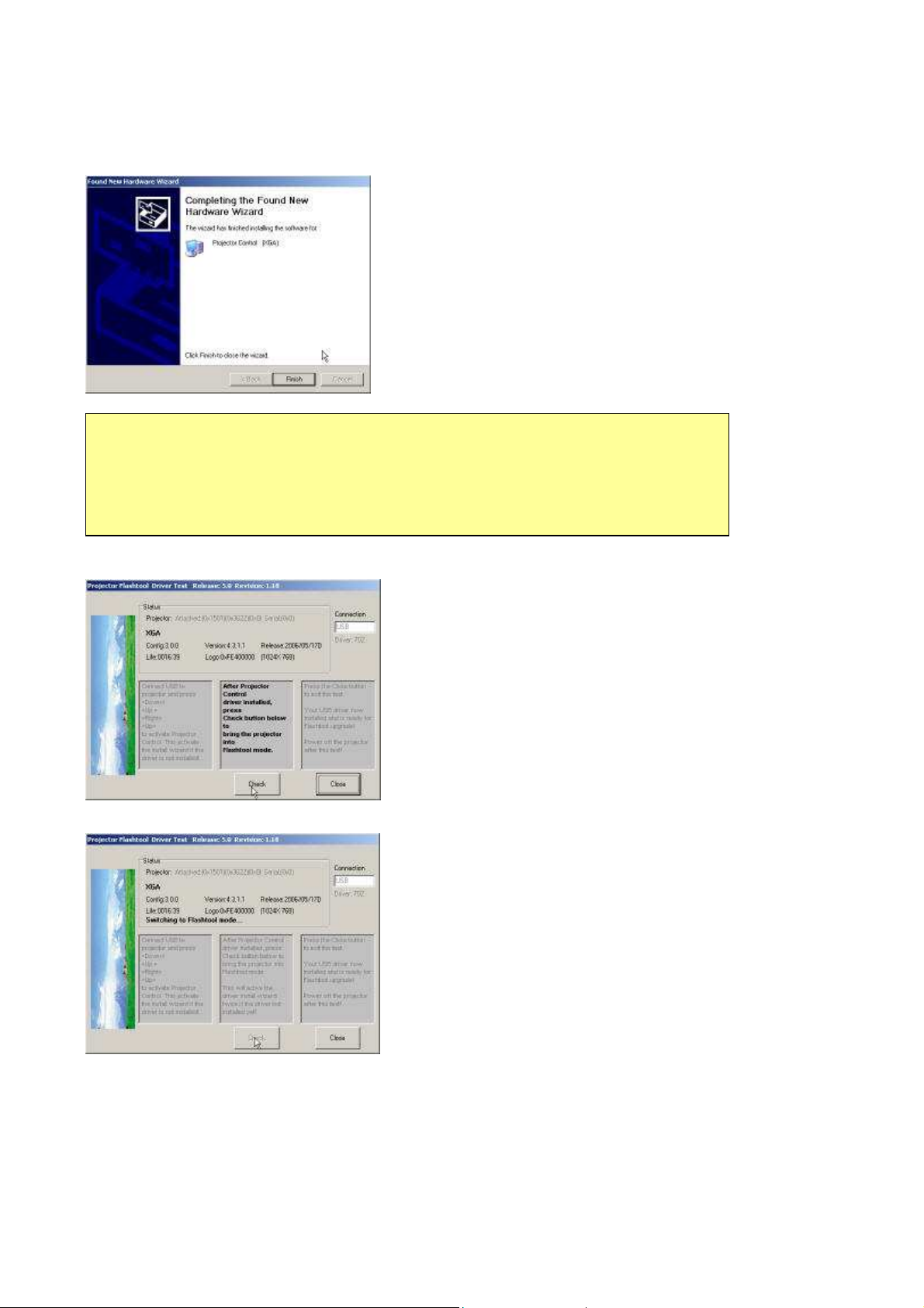
Windows completes the new hardware wizard.
Press the “Finish” button to exit.
Note:
In case that you has USB enumeration problem (i.e., the USB port cannot recognize your
projector), please clear all USB items in the windows registry, and re-install the Flash-Tool
USB driver. See Appendix-A for further details.
Once when the Projector Control USB driver is enumerated, the
projector information is displayed in the status window.
Click on the “Check” button to place the projector in the
Flash-Tool mode.
The purpose of this function is to verify whether or not the project is
successfully in the Flash-Tool mode.
The projector is now in the Flash-Tool mode after the click.
Company Confidential Optoma___________________ Delta________________
63
2008/09/17
Page 64
Delta Elec. Inc. ES520 & EX530 ver.02
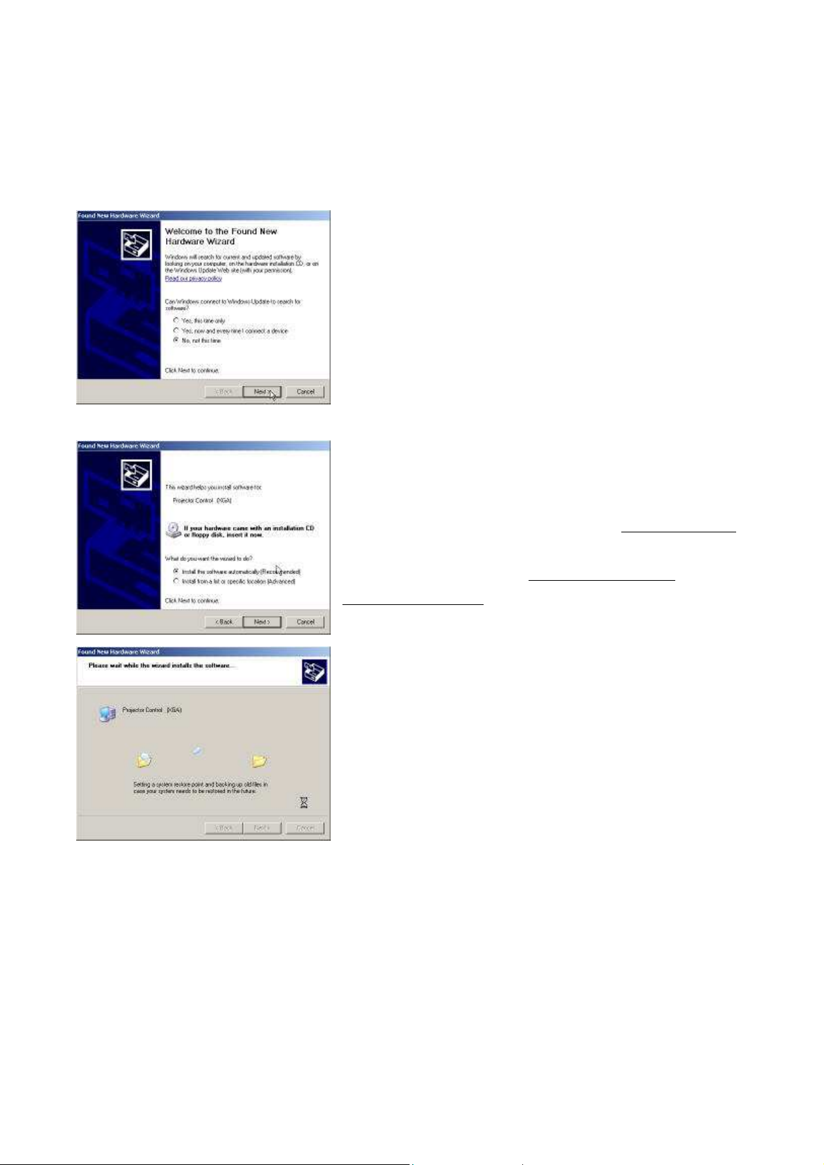
The Windows New Hardware Wizard will launch again for the second USB Projector Control.
Select “No, not this time”
Click on the “Next” button to continue
Select “Install the software automatically”
Click on the “Next” button to continue
* In case the wizard cannot find the driver (the ProjectorControl.inf),
please select the other advanced option and specify the driver
location manually. (Normally at
Projector\Projector Flash Tool
)
C:\Program Files\Digital Zoom
Windows updates the USB Projector Control driver when found
Company Confidential Optoma___________________ Delta________________
64
2008/09/17
Page 65
Delta Elec. Inc. ES520 & EX530 ver.02
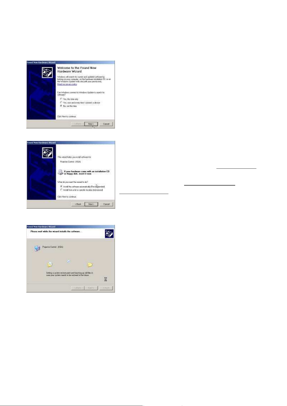
The New Hardware Wizard launches, and Windows detects a new
USB device attached.
Select “No, not this time”
Click on the “Next” button to continue
Select “Install the software automatically”
Click on the “Next” button to continue
* In case the wizard cannot find the driver (the ProjectorControl.inf),
please select the other advanced option and specify the driver
location manually. (Normally at
Projector\Projector Flash Tool
)
C:\Program Files\Digital Zoom
Windows updates the USB Projector Control driver when found
Company Confidential Optoma___________________ Delta________________
65
2008/09/17
Page 66
Delta Elec. Inc. ES520 & EX530 ver.02
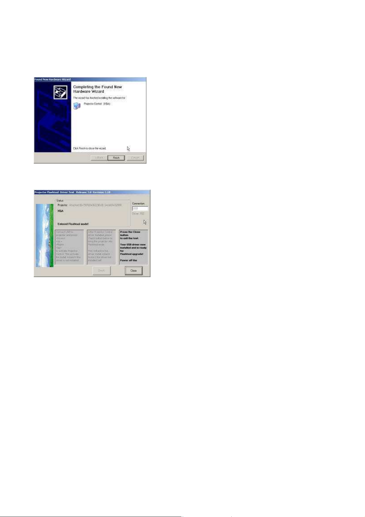
Windows completes the new hardware wizard.
Press the “Finish” button to exit
Congratulations!
Power off the projector now
Your driver has been checked and works for Flash-Tool.
Company Confidential Optoma___________________ Delta________________
66
2008/09/17
Page 67

Delta Elec. Inc. ES520 & EX530 ver.02
Appendix-A
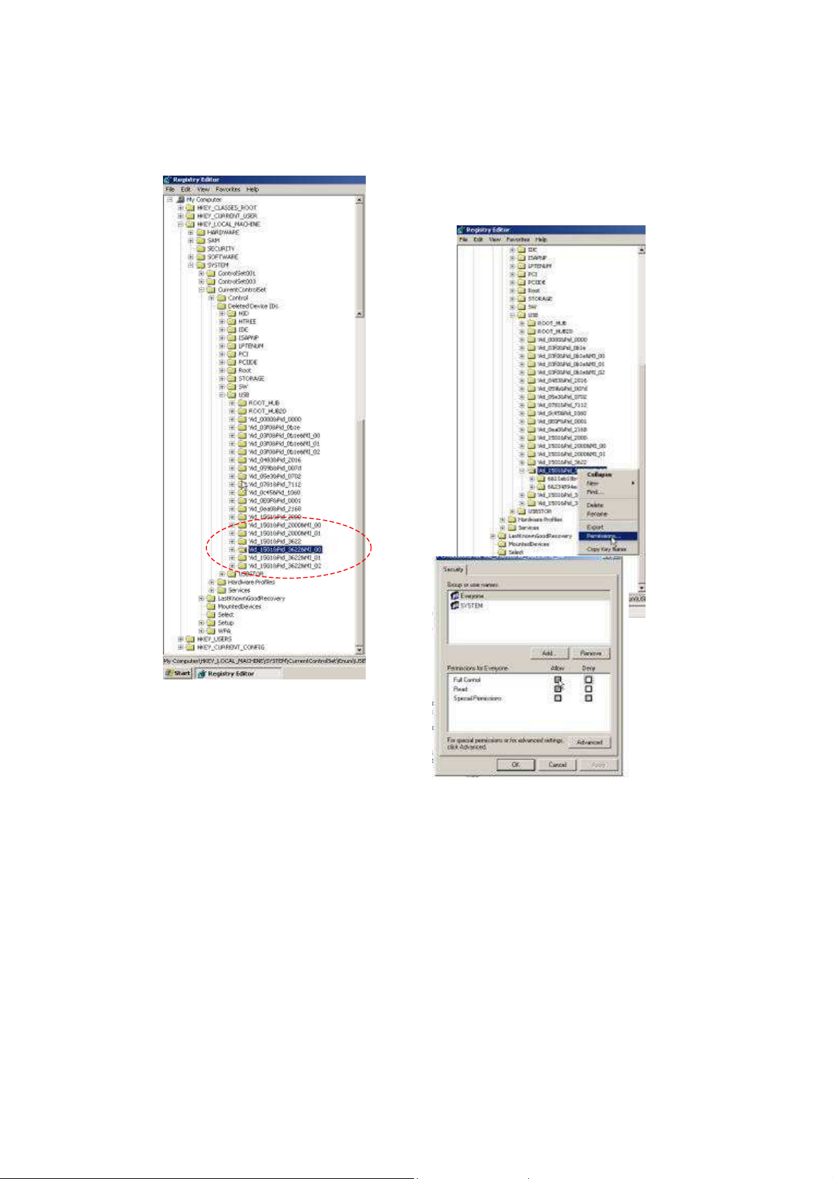
How to clear the USB enumeration registry?
Run “regedit” and select the following items
HKEY_LOCAL_MACHINE->SYSTEM->CurrentControlSet->Enum->USB->
The E400/AV/DP2601 VID_1501&Pid_2601xxx
The AV/DP2618 series VID_1501&Pid_2618xxx
The AV/DP3618 series VID_1501&Pid_3618xxx
The DP3602 series VID_1501&Pid_3602xxx
The DP3616 series VID_1501&Pid_3616xxx
The DP3622 series VID_1501&Pid_3622xxx
The PR301x series VID_1501&Pid_2617xxx
The PR302x series VID_1501&Pid_3617xxx
The PR50xx series VID_1501&Pid_3622xxx
The EP77x series VID_1501&Pid_3622xxx
The DDP2230 series VID_1501&Pid_2230xxx
…
Press <Delete> and remove these registries. (You need the read/write privilege of the Windows registry to delete
it. Select the item and click right mouse will lead you to the Permissions dialog for applying the security options)
Company Confidential Optoma___________________ Delta________________
67
2008/09/17
Page 68
Delta Elec. Inc. ES520 & EX530 ver.02
Company Confidential Optoma___________________ Delta________________
68
2008/09/17
Page 69
Delta Elec. Inc. ES520 & EX530 ver.02
Appendix-B
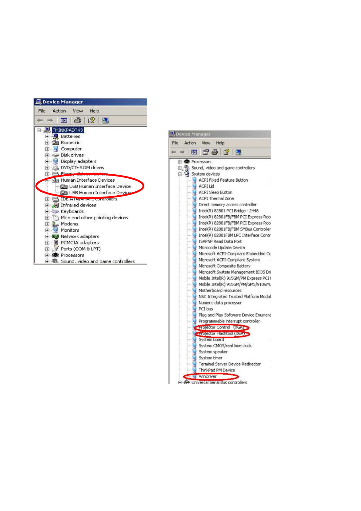
Projector USB status on Windows Device Manager
The USB HID device will be installed automatically via Windows' USB hot-plug mechanism.
The Projector Control will be dynamically installed after entering the maintenance mode
(Press <down>, <up>, <right>, <up> key in sequence); The Projector Flashtool will be dynamically installed when
starting the flash upgrading by Flashtool or FlashtoolBL utility.
The Windriver is the root driver for both Projector Control and Flashtool.
Company Confidential Optoma___________________ Delta________________
69
2008/09/17
Page 70

Delta Elec. Inc. ES520 & EX530 ver.02
5-2.
DLP Projector Flash-Tool (firmware) User Guide
Ver 6.0.0.4
The document is to describe a Windows application software “Flash-Tool” for projector firmware. Its main
purpose is to provide a detailed procedure of upgrading the application software of a DLP projector. The system
requirement and the installation procedure of “Flash-Tool” are also included in the document.
NOTE:
User must have administrative privileges on the target computer in order to
install the driver. (The installation target directory must not be write-protected.)
User also required having the basic knowledge of Windows application installation.
Attention: This utility is for DLPTM DDP2000/2230 series projectors only.
System Requirement of Flash Tool
IBM compatible PC.
Windows XP SP2 operating system (English).
Projector with Flash-Tool USB driver installed
Installation of Flash-Tool
Execute the file of “Digital Zoom Projector Flash Tool Vx.y.msi”.
Note: If your projector USB driver is not installed yet, please refer to the USB driver installation guide for further
details.
Company Confidential Optoma___________________ Delta________________
70
2008/09/17
Page 71
Delta Elec. Inc. ES520 & EX530 ver.02
5-3.
Start with Flash-Tool
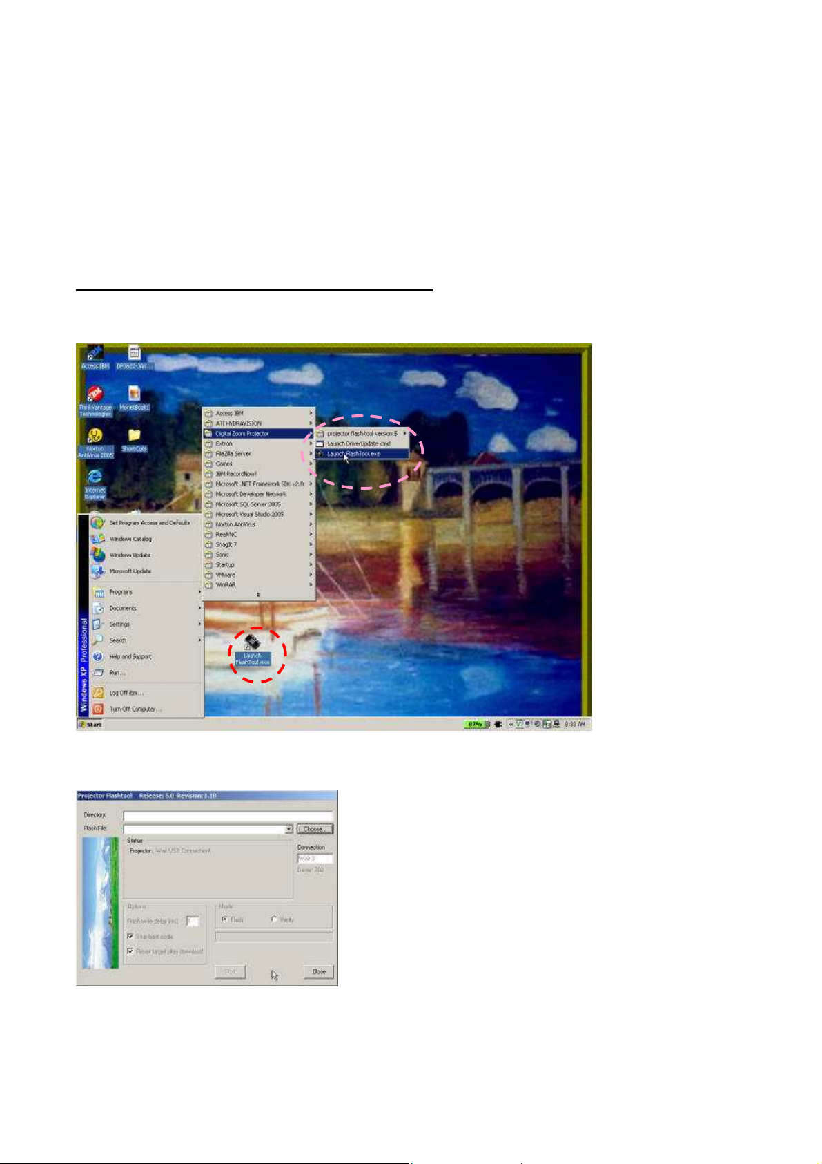
The section is to illustrate the procedure to upgrade the application software of a DLP projector.
Step 1: Launch the “FlashTool.exe” from installed shortcut at
Program > Digital Zoom Projector> Launch FlasTool.exe or click on the “Launch FlashTool.exe” shortcut icon
on the desktop.
Step 1-1: While executed, a Flash-Tool window shall appear as the following picture.
Company Confidential Optoma___________________ Delta________________
71
2008/09/17
Page 72
Delta Elec. Inc. ES520 & EX530 ver.02
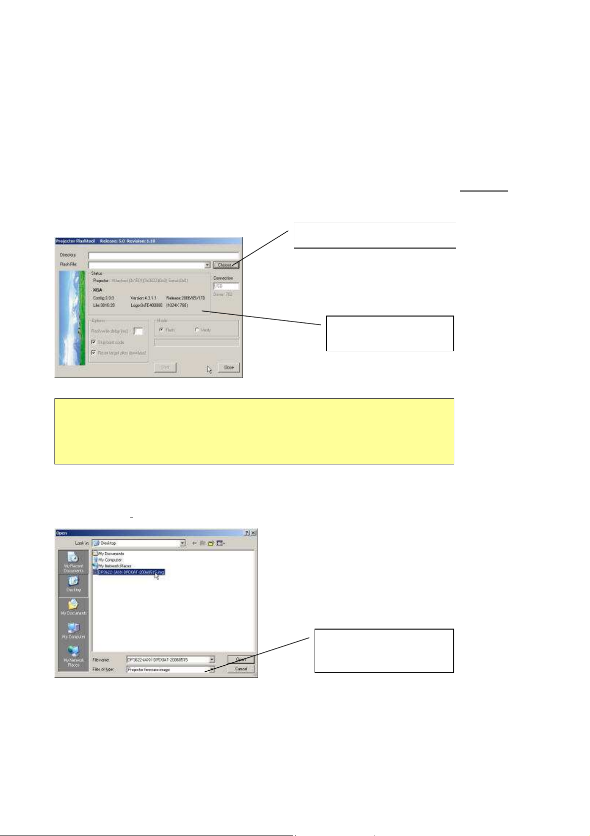
Step 2: Make sure that the USB cable is firmly connected between projector and computer
Step 3: Connect the power cord to the projector, and move the power switch in its ON position (if available) so
that projector is in STAND BY mode.
Step 4:
remote controller for those with limited keypads. The power and lamp LED shall blink and the Flash-Tool mode
will be enabled.
Press
<Down>, <Up>, <Right>, <Up>
keys in sequence using keypad buttons, or using the IR
Press “Choose” to select file
Projector information
Note:
The Windows hardware wizard will pop up if the USB device driver is not installed.
Simply select the recommended options, and let Windows Wizard does the trick.
.
Step 5: Press the “Choose” button to locate the new firmware which can be downloaded from website (for
example: DP3622-JAXX-DPD0A.img). Select the desired .img file by either double clicking the file, or pressing
the “Open” button.
Use .img file type for
firmware binary data
Company Confidential Optoma___________________ Delta________________
72
2008/09/17
Page 73
Delta Elec. Inc. ES520 & EX530 ver.02
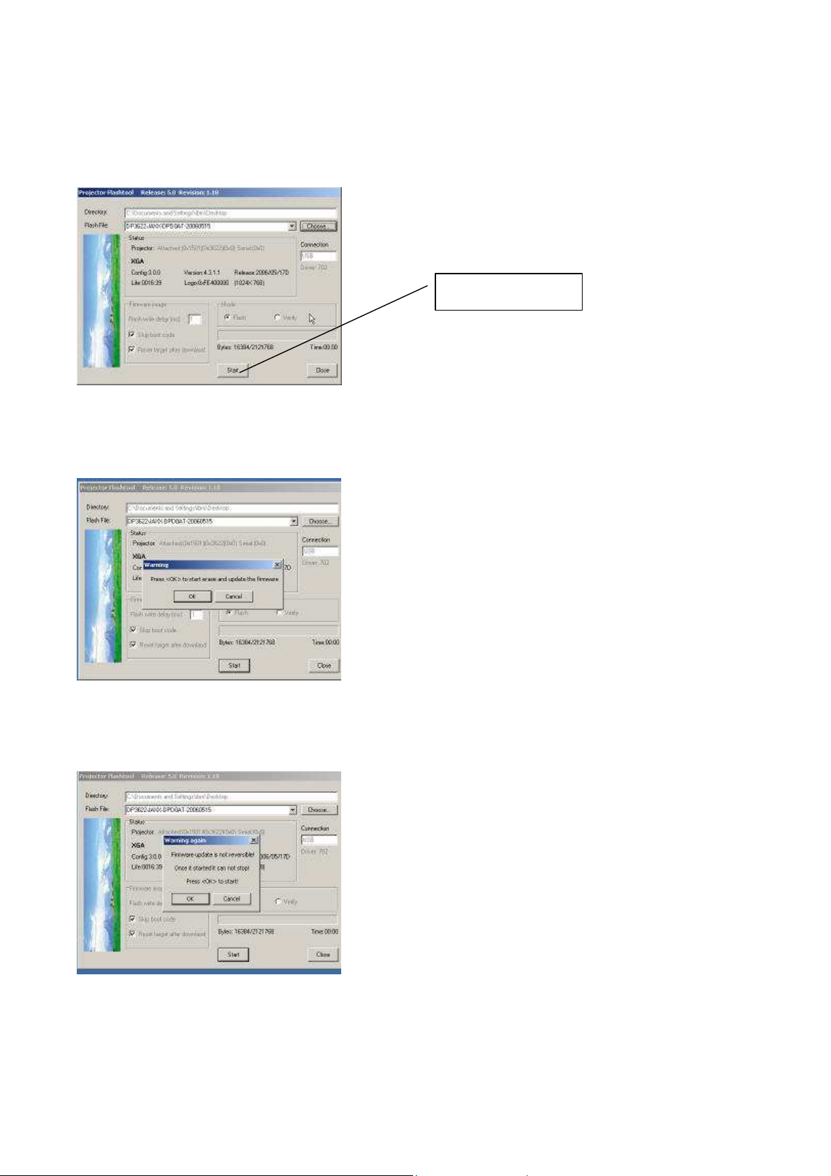
The “Start” button
Note: The Flash-Tool will validate the signature of the binary image file for upgrading. The “Start” button will not
enable if the binary image is not a valid projector firmware.
Step 6: Press the “Start” button to update the flash with the chosen firmware. A warning message box will
appear for confirmation. Press <OK> to continue.
Step 7: When the last warning message box appears, this is the last chance to cancel the update. Press “OK”
button to start the firmware update.
Company Confidential Optoma___________________ Delta________________
73
2008/09/17
Page 74
Delta Elec. Inc. ES520 & EX530 ver.02
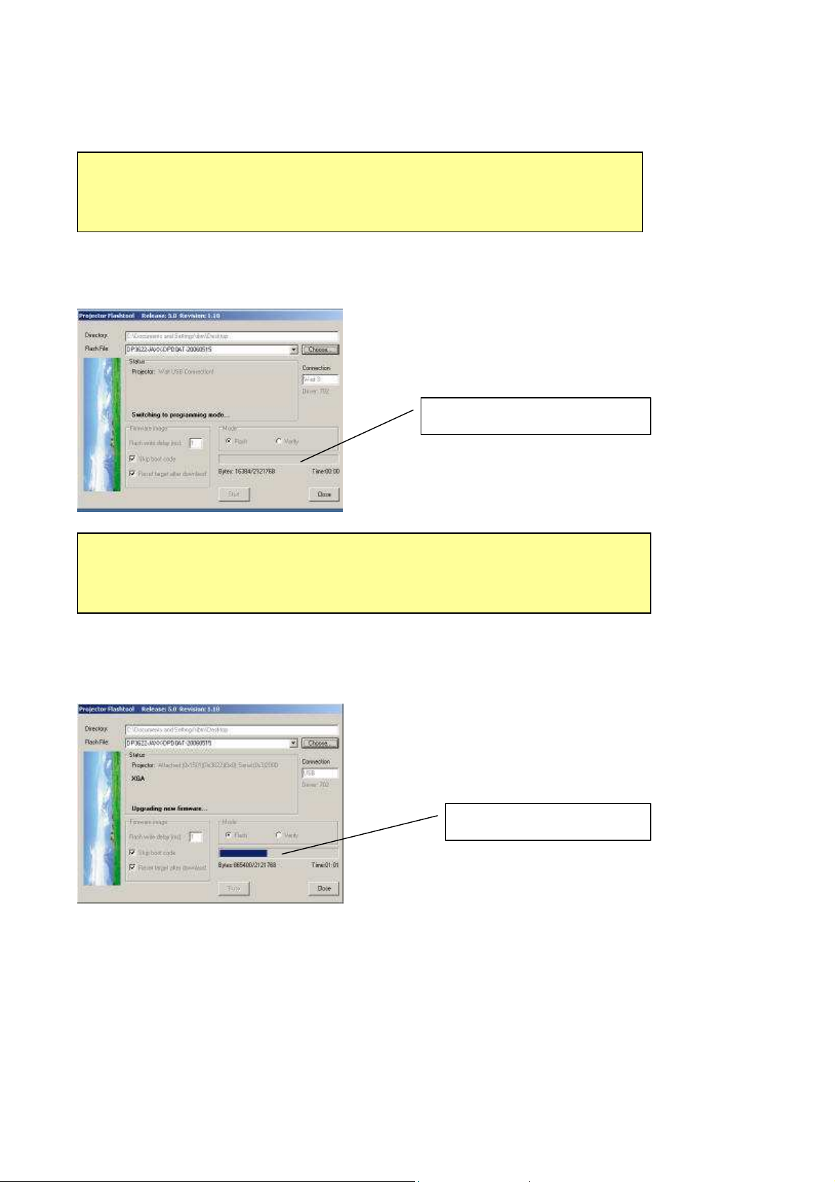
Caution:
DO NOT install any USB driver when erasing or upgrading process started.
Note: According to the Flash technology, the old firmware will be erased first. Therefore, Flash-Tool will
automatically erase the old firmware before upgrading.
Erasing status
Caution:
DO NOT install any USB driver when erasing or upgrading process started.
Note: After old firmware is erased, the new firmware upgrading process will start.
Upgrading new firmware
Company Confidential Optoma___________________ Delta________________
74
2008/09/17
Page 75
Delta Elec. Inc. ES520 & EX530 ver.02
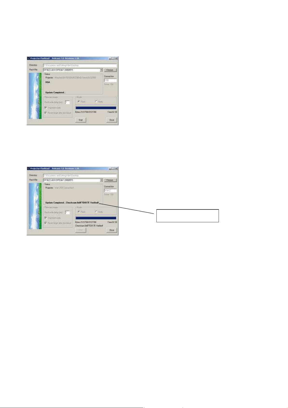
Note: After the new firmware is upgraded, the Flash-Tool will perform the final validation. The dialog shows the
checksum with a verification message!
Checksum verified
Step 8: When the validation is completed, turn off the projector. Next time when the projector is on, it
will execute the new firmware.
Company Confidential Optoma___________________ Delta________________
75
2008/09/17
Page 76
5-4.
Delta Elec. Inc. ES520 & EX530 ver.02
Starting and Shutting down the Projector
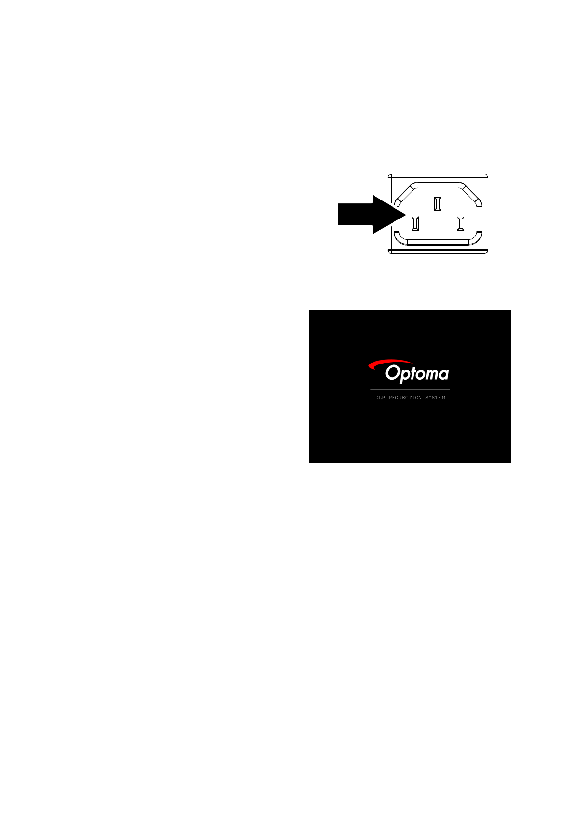
Connect the power cord to the
1.
projector.
Turn On the connected devices.
2.
Ensure the Power LED is steady
3.
(flashing) and then press the Power
button to turn On the projector.
The projector splash screen displays
and connected devices are detected.
If the connected device is a PC, press
the appropriate keys on the computer
keyboard to switch the display output
to the projector. (Check the user
manual of the PC to determine the
appropriate Fn key combination to
change display output.)
Company Confidential Optoma___________________ Delta________________
76
2008/09/17
Page 77
Delta Elec. Inc. ES520 & EX530 ver.02
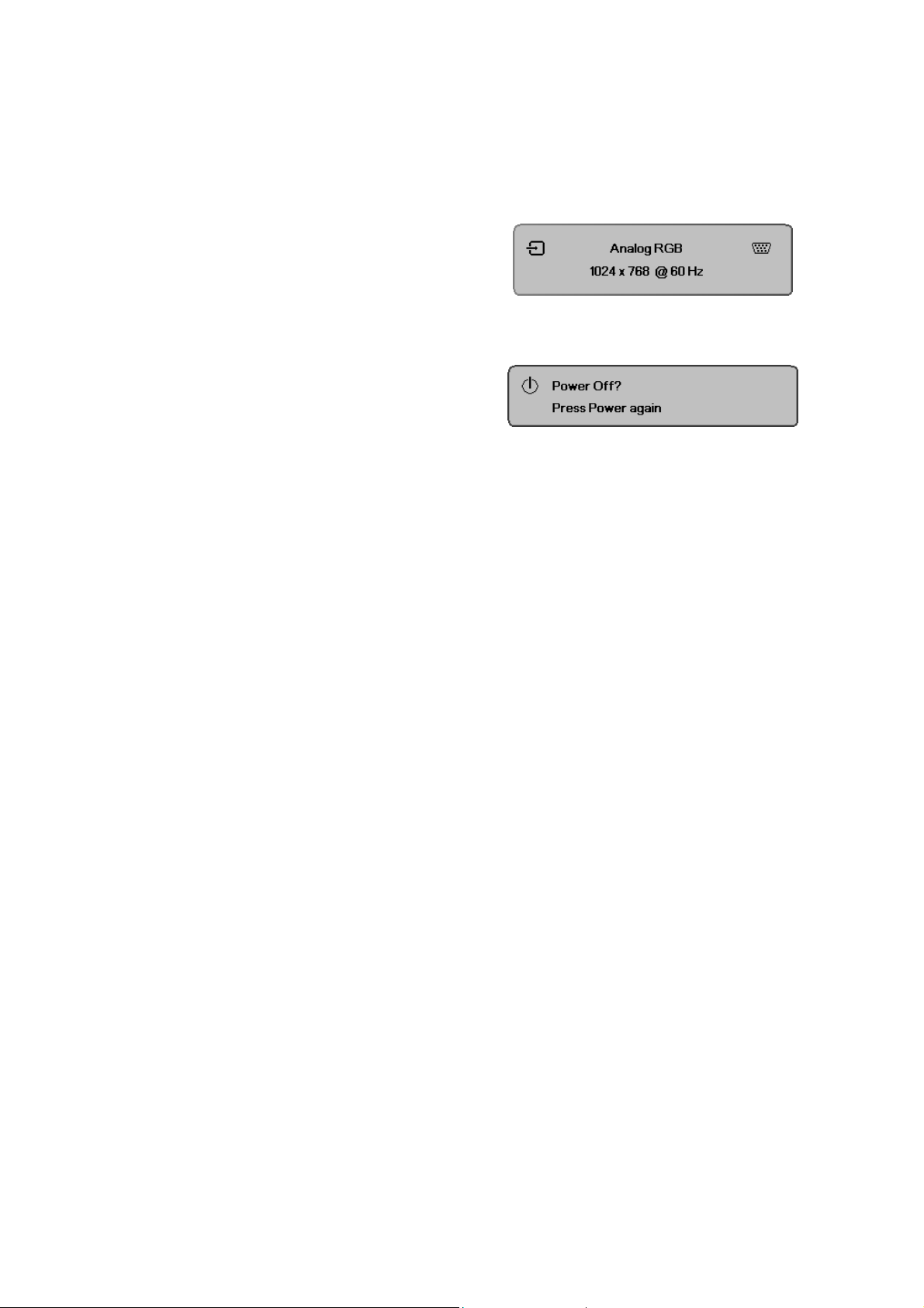
If more than one input device is
4.
connected, press the
Source
button
repeatedly to switch among devices.
(DVD and HDTV are supported
through the VGA connector)
To turn off the projector, press the
5.
power button. The
Power Off? /
Press Power again
appears. Press the
message
Power
button
again to turn off the projector.
Caution:
Do not unplug the power cord until the Lamp LED (on Cooling mode) stops flashing–indicating
the projector has cooled down.
5-5.
Setting an Access Password (Security Lock)
You can use the Remote digital buttons to set a password and prevent unauthorized use of the
projector. When enabled, the password must be entered after you power on the projector.
Keep the password in a safe place. Without the password, you will not be able to use the
projector. If you lose the password, contact your reseller for information on clearing the
password.
Company Confidential Optoma___________________ Delta________________
77
2008/09/17
Page 78
Delta Elec. Inc. ES520 & EX530 ver.02
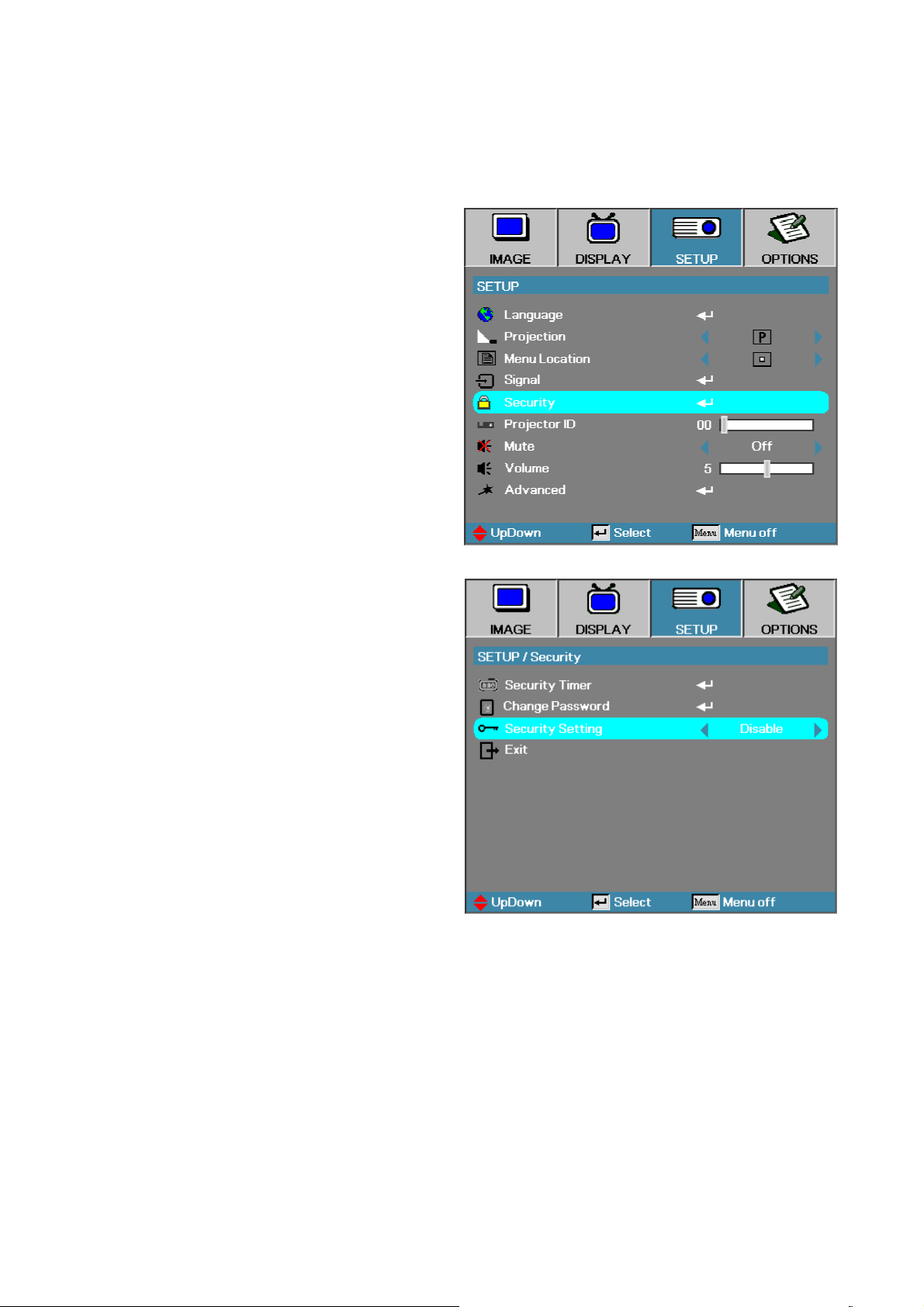
1.
2.
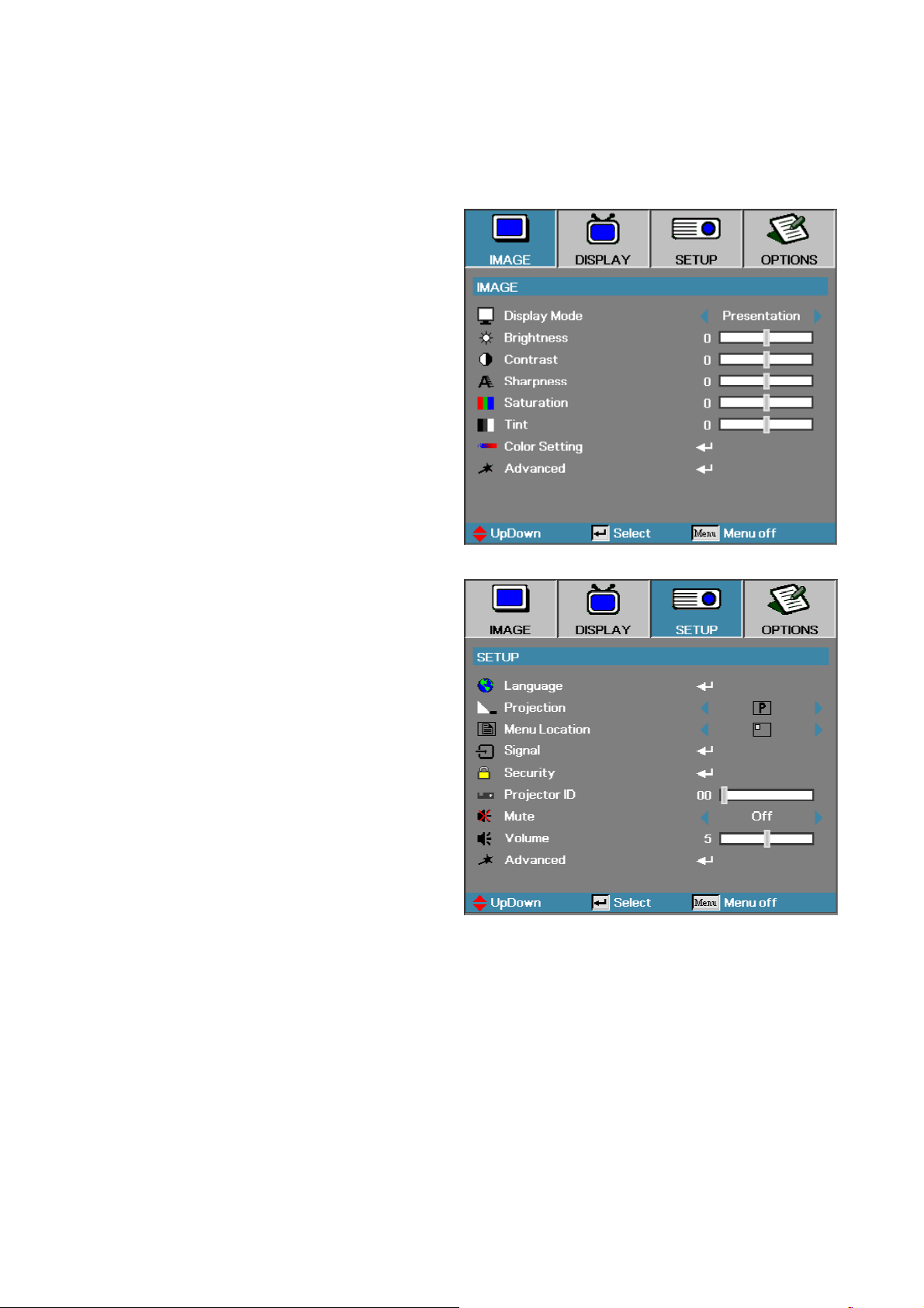
Press the
Menu
button to open the
OSD menu.
Press ◄► to move to the
menu.
SETUP
Company Confidential Optoma___________________ Delta________________
78
2008/09/17
Page 79
Delta Elec. Inc. ES520 & EX530 ver.02
3.
4.
Press ▲▼ to select
Press ▲▼ to select
Setting
select
and then press ◄► to
Enable/Disable
Security
Security
.
.
Company Confidential Optoma___________________ Delta________________
79
2008/09/17
Page 80
Delta Elec. Inc. ES520 & EX530 ver.02
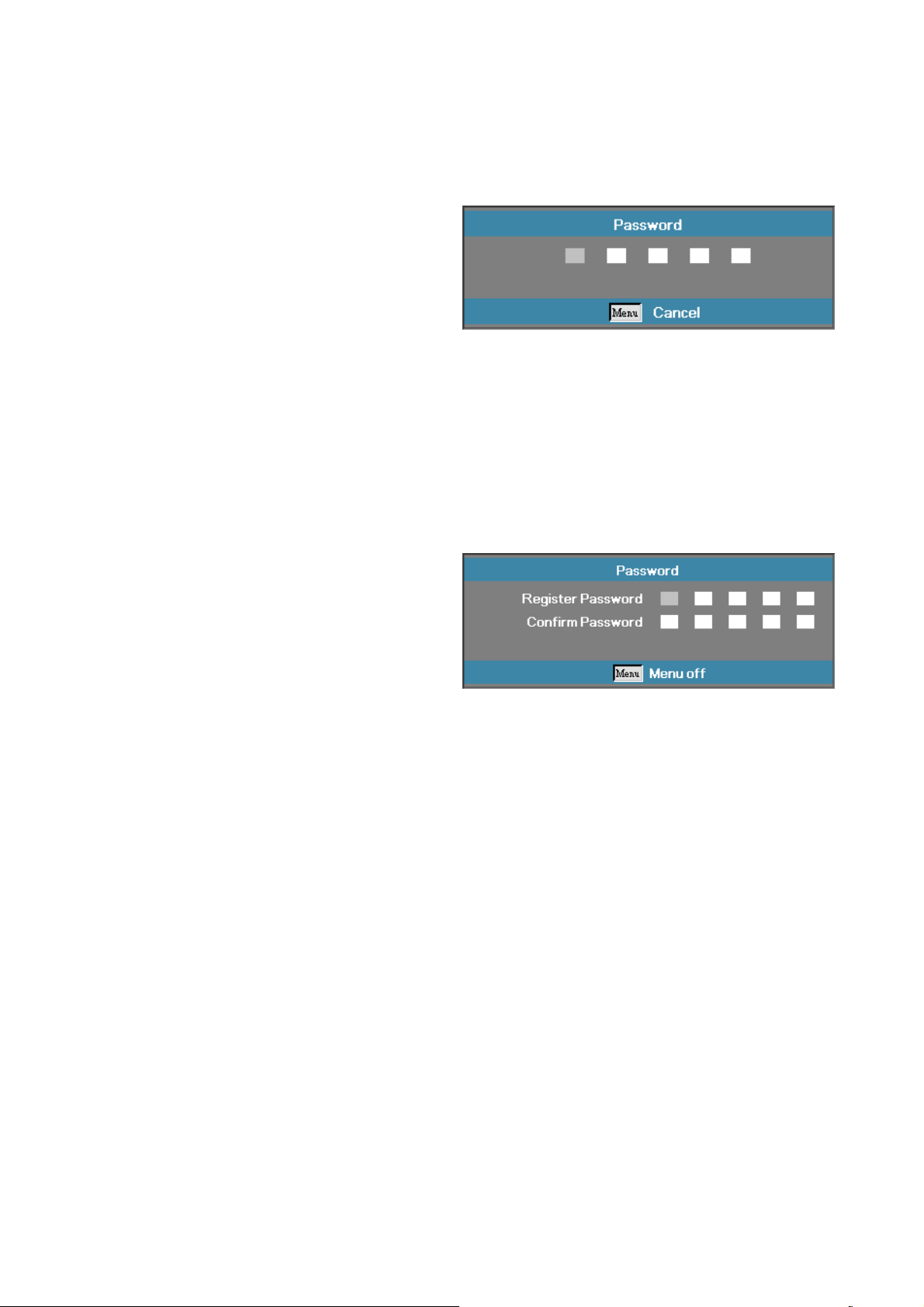
5.
6.
7.
When the security setting is
Enabled
, you are prompted to
enter a password soon after the
projector is powered on.
Note:
If the incorrect password is
entered three times the projector
auto shutdowns down after 10
seconds.
The default password is: <1>
<2> <3> <4> <5>.
To change a password, enter the
previous password when prompted.
Use the following keys <1>, <2>,
<3>, <4>, <5>, <6>, <7>, <8>, <9>
to define a new password.
Company Confidential Optoma___________________ Delta________________
80
2008/09/17
Page 81
Delta Elec. Inc. ES520 & EX530 ver.02
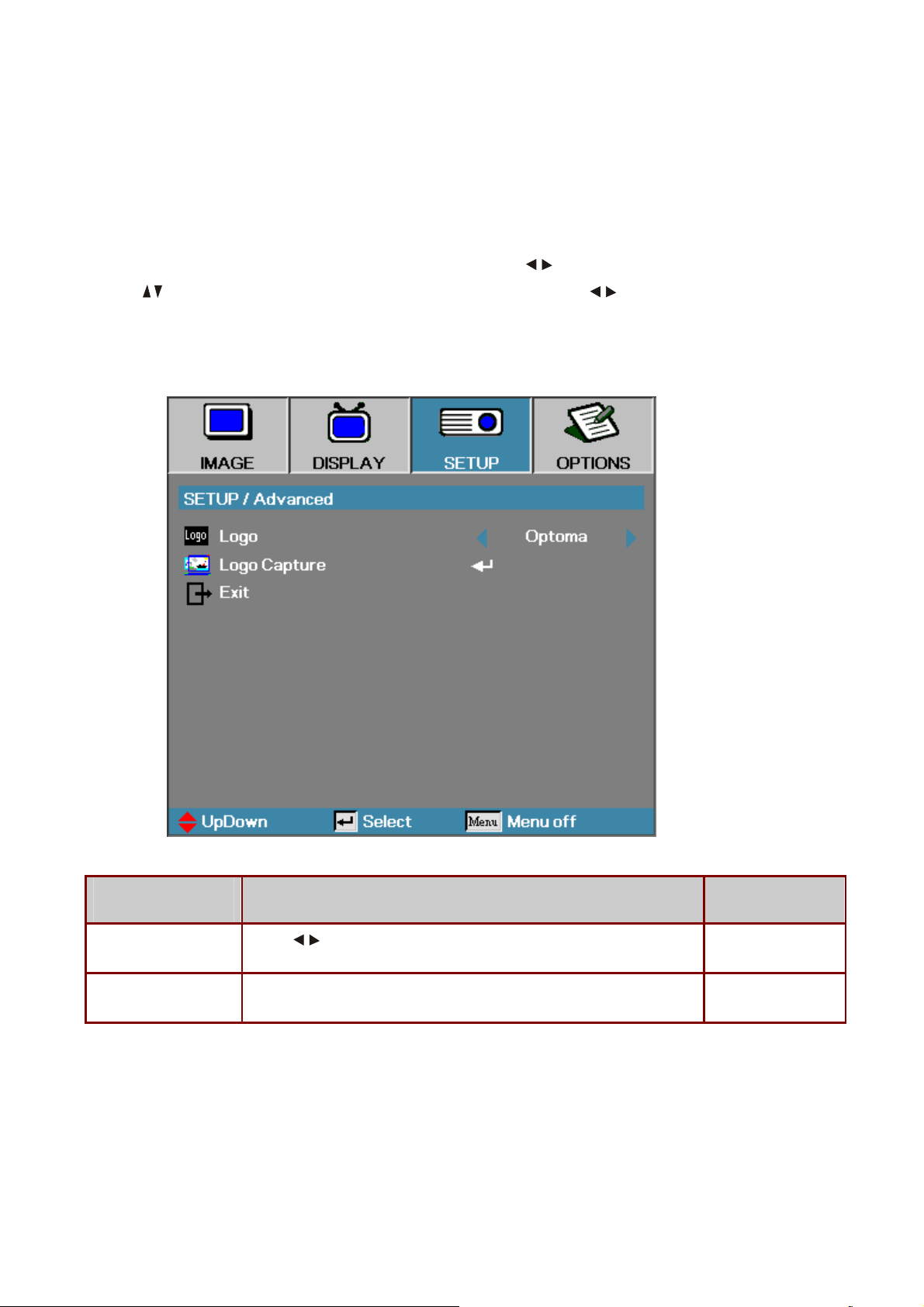
5-6.
SETUP / Advanced
Press the
Menu
button to open the OSD menu. Press to move to the
SETUP
menu.
Press to move up and down and select
settings, and then press
Enter
to confirm the new setting.
Advanced
. Press to change values for
I
TEM
D
Logo
Logo Capture Capture the current display image as the user’s logo with
Company Confidential Optoma___________________ Delta________________
81
Press
to select the desired startup screen.
ESCRIPTION
D
Logo Capture
.
EFAULT
Optoma
-
2008/09/17
Page 82
Delta Elec. Inc. ES520 & EX530 ver.02
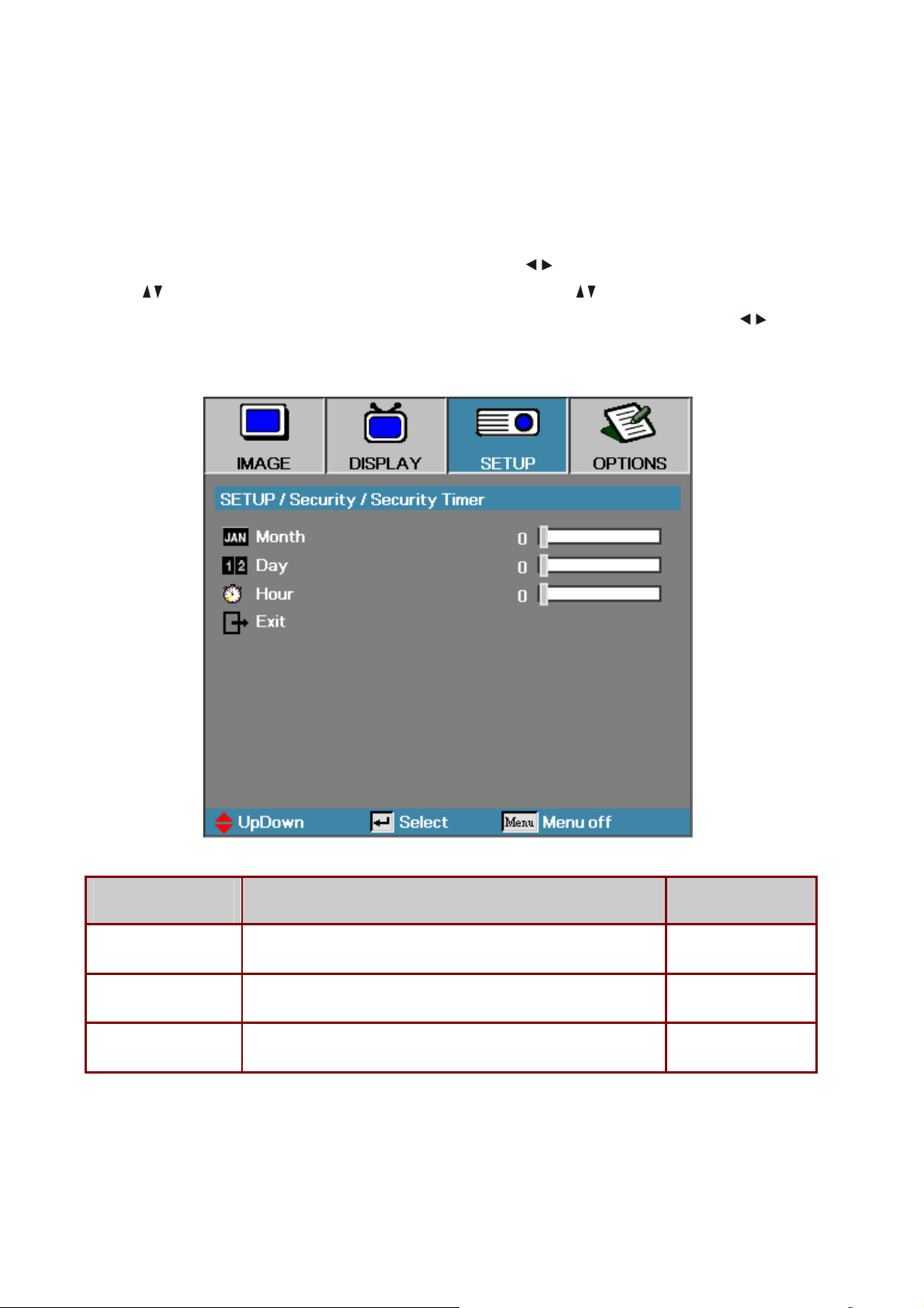
5-7.
Security Timer
Press the
Menu
button to open the OSD menu. Press to move to the
SETUP
menu.
Press to move up and down and select
select
Security Timer
. Press
Enter
to open the
change values for settings, and then press
Security
Security Timer
Enter
to confirm the new setting.
. Press to move up and down and
submenu. Press to
I
TEM
D
Month Set the number of months the projector can be used. 0
Day Set the number of days for the projector to be active. 0
Hour Set the number of hours for the projector to be active. 0
Company Confidential Optoma___________________ Delta________________
82
ESCRIPTION
D
EFAULT
2008/09/17
Page 83
Delta Elec. Inc. ES520 & EX530 ver.02
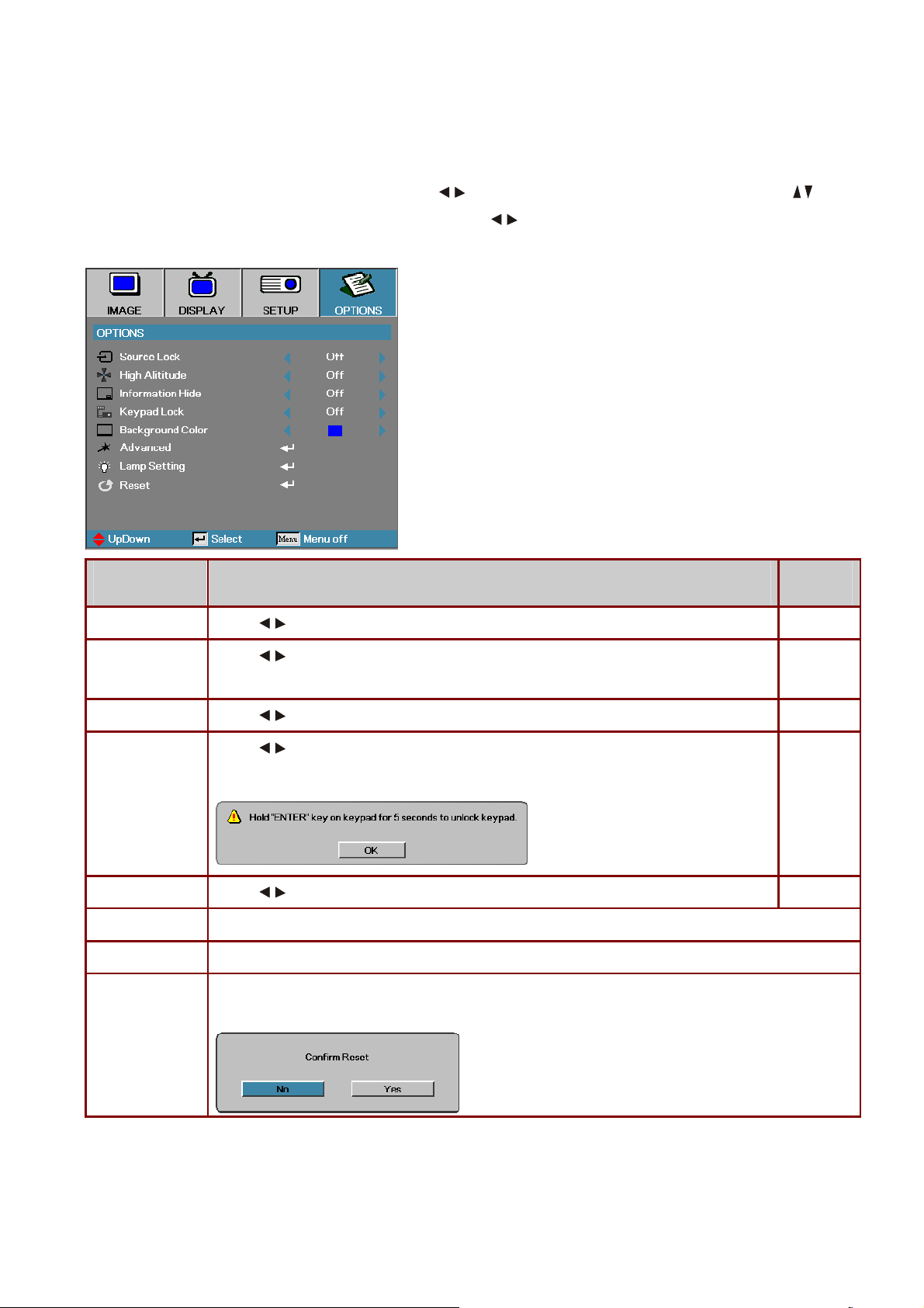
5-8. Options Menu
Press
Menu
to open the OSD menu. Press to move to the
OPTIONS
menu. Press to
move up and down in the
press
Enter
TEM
I
Source Lock
High Altitude
to confirm the new setting.
D
Press to enable or disable the automatic search of all the input sources.
Press to change fan speed; high speed in high temperature, high humidity or high
OPTIONS
menu. Press to change values for settings, and then
EFAULT
ESCRIPTION
D
Off
Off
altitude area.
Information Hide
Keypad Lock
Background Color
Advanced Press
Lamp Setting Press
Reset Press
Press to enable or disable the source searching, source resolution, and logo display.
Press to enable or disable keypad function.
The following warning message appears when you select On.
Press to select different colors or blank screen.
Press
Enter
to open the
Enter
to open the
Enter
to reset all menu items to factory default. The following screen displays.
Yes
to confirm.
OPTIONS/Advanced
OPTIONS/Lamp Setting
menu.
menu.
Off
Blue
Company Confidential Optoma___________________ Delta________________
83
2008/09/17
Page 84
Delta Elec. Inc. ES520 & EX530 ver.02
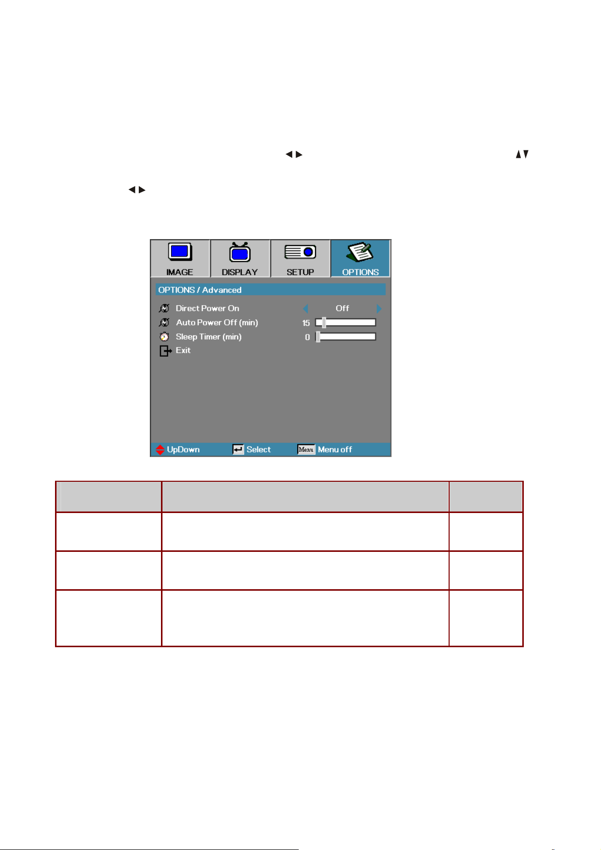
5-9.
OPTIONS / Advanced
Press
move up and down in the
Menu
to open the OSD menu. Press to move to the
OPTIONS
menu. Select
Advanced
and press
menu. Press to change values for settings, and then press
setting.
OPTIONS
Enter
Enter
to confirm the new
menu. Press to
to open the sub
I
TEM
D
Direct Power On If the user selects On the projector will automatically power on when
AC power is supplied.
Auto Power Off (min) Set the projector to automatically switch off the lamp when there is no
signal after 15 minutes.
Sleep Timer (min) Sets the countdown timer interval. The timer will begin, with or without
a signal input. Then the projector will automatically power Off when the
sleep timer countdown stops (in minutes).
Note
:
ESCRIPTION
DEFAULT
Off
15
0
Press any keypad/IR button to restore the original timer setting when a warning message
displays.
Company Confidential Optoma___________________ Delta________________
84
2008/09/17
Page 85
Delta Elec. Inc. ES520 & EX530 ver.02
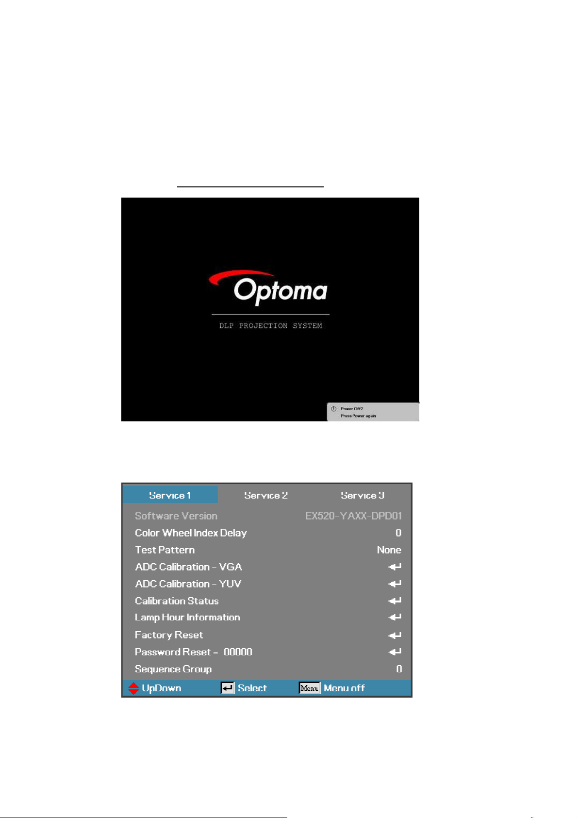
6. Calibration
Step of into Service Mode
Step 1 : To turn on the projector, press the Power button on the keypad or IR controller,
.
Until the “Power Off? Press Power again” message appears.
Step 2:Then press “Left”=>“Right”=>“Down”=>“Up” button on the keypad or IR controller.
Step 3:If password is correct then go into Service Mode。
Company Confidential Optoma___________________ Delta________________
85
2008/09/17
Page 86
Delta Elec. Inc. ES520 & EX530 ver.02
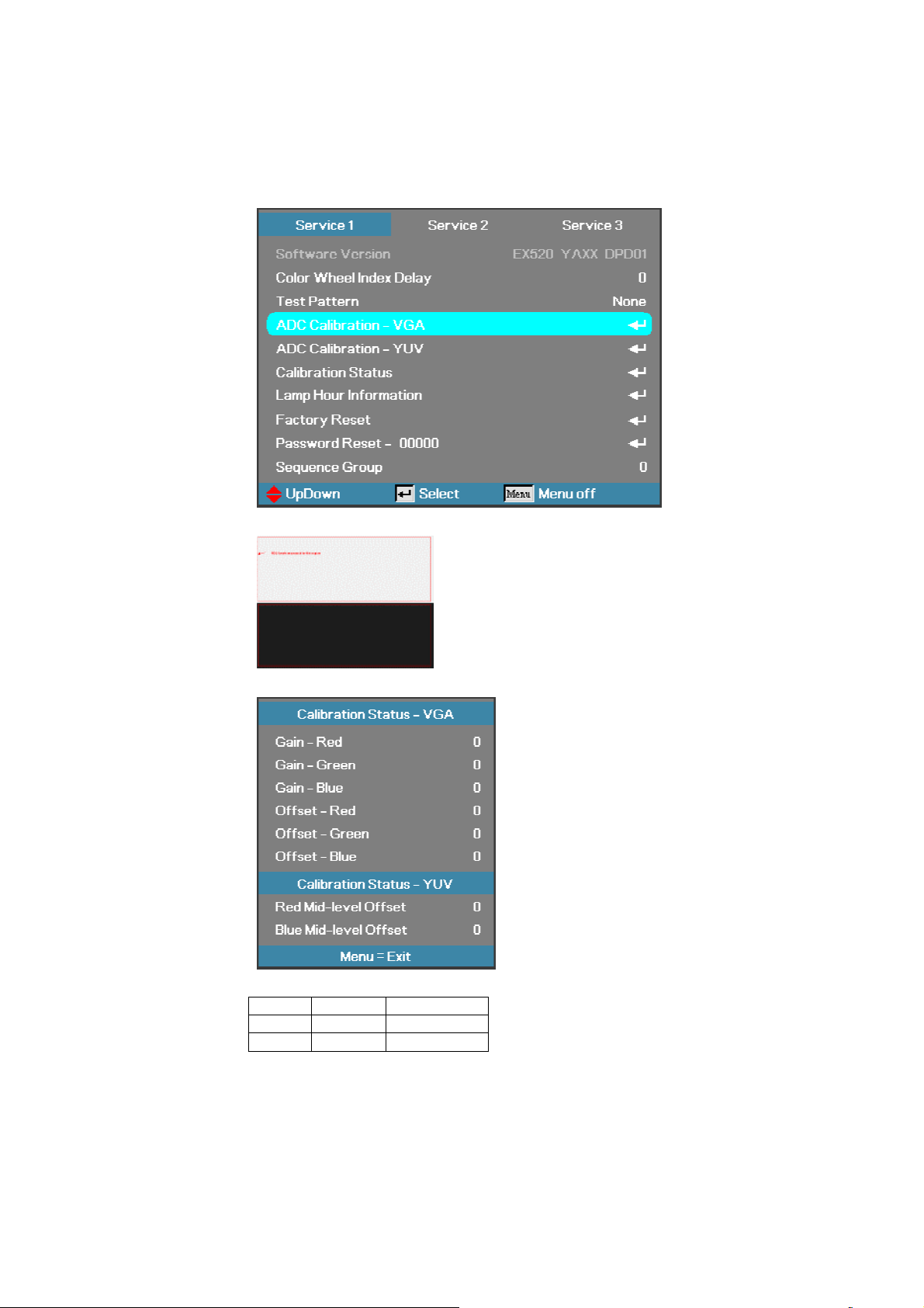
6-1. Calibrate Analog RGB (1024 x 768 @ 60Hz):
Step 1: In Service 1Mode select ADC Calibration - VGA In this menu input pattern with White(240,240,240)
and Black(16,16,16) for calibrate VGA Source . After input ready press “Enter” key to calibration。
Input Pattern
Step 2 : After complete the OSD will show the picture as follow , if not complete, just close the OSD。
Note : Offset & Gain Value
Default After ADC
Offset 511
Gain 511
Step 3 : Compare internal white pattern and RGB source white pattern, if the brightness gap ratio of these two
source is bigger than 3.5%.
Company Confidential Optoma___________________ Delta________________
86
2008/09/17
Page 87
Delta Elec. Inc. ES520 & EX530 ver.02
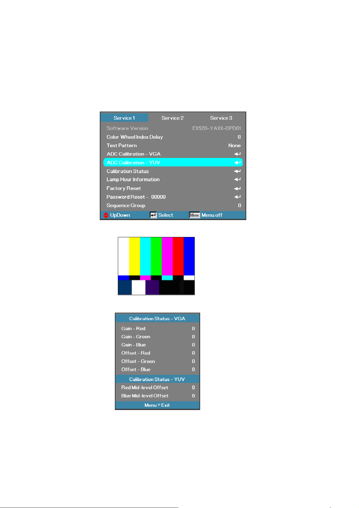
6-2. Calibrate Analog YUV:
Equipment: VG828, must be take off H/V sync terminal from machine
Step 1: In Service 1 Mode select ADC Calibration - YUV. In this menu input pattern with 75﹪SMPTE
pattern for calibrate YUV Source and notice that the input source must be 480i format 。
After input ready press “Enter” key to proceed。
Input Pattern
.
Step 2 : After complete the OSD will show the picture as follow, if not complete, just close the OSD。
NOTE:
You can select Calibration Status – VGA or Calibration Status –
YUV item to watch the calibrated value at any time。
Company Confidential Optoma___________________ Delta________________
87
2008/09/17
Page 88
Delta Elec. Inc. ES520 & EX530 ver.02
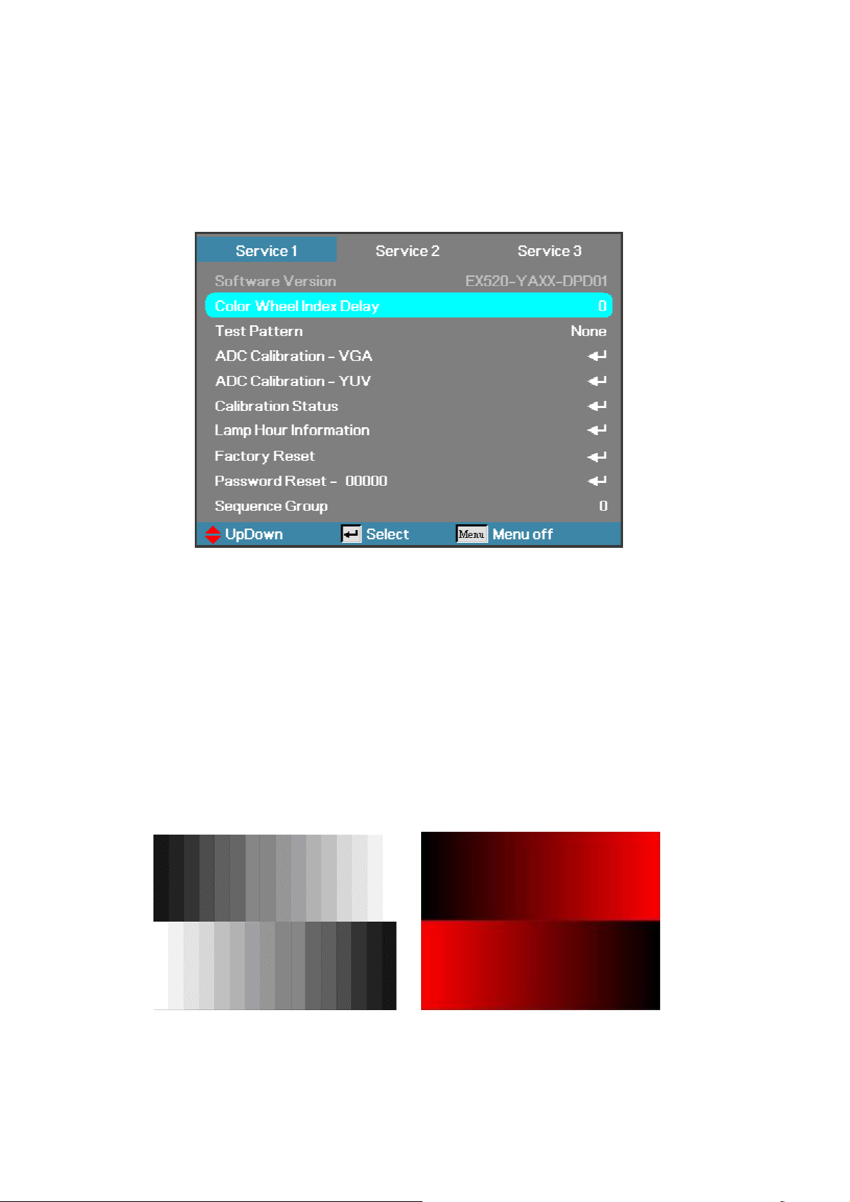
6-3. Color Wheel Index, DMD Contrast and Brightness Adjustment @ RGB source
A. Switch Timing to ”1024x768 @ 60HZ”
B. In Service 1mode.
C. Switch to the Pattern 48 “32 Gray Scale”, and then decrease the Brightness Default Diff until all
black gray scales are still distinct.
D. Switch to the Pattern 48 “32 Gray Scale”, and then increase the Contrast Default Diff until all
white scales are still distinct.
E. Select “Color Wheel Index Delay”.
The adjustment range is 0~719.
F. Switch Pattern 47 “16 Gray Scale”. Fine-tune until the gray scale still distinct. Decrease the color
to the minimum. Then switch pattern 48 “32 Gray Scale”, tune off G, B channel, check the smooth
in brighter level of the R 32 ramp. If not, fine tune “CW INDEX Delay Time” until R 32 ramp
smooth.
Brightness and Contrast need to measure with RGB source
”1024x768 @ 60HZ”
Company Confidential Optoma___________________ Delta________________
88
2008/09/17
Page 89
Delta Elec. Inc. ES520 & EX530 ver.02
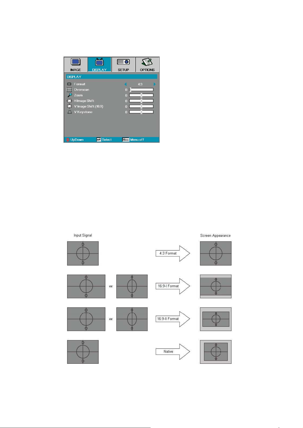
6-4. Display Test
Format - Use this function to choose your desired aspect ratio.
1. 4:3: Format is for 4x3 input sources not enhanced for Wide screen TV.
2. 16:9 I: This format is for 16x9 input sources, like HDTV and DVD
en- hanced for Wide screen TV.
3. 16:9 II: The non-standard wide-screen display format of the projector.
Part of the original image will be cut if the image aspect ratio is less than
1.67:1.
4. Native: Depends on the resolution of the display.
5. Auto: Automatically selects the appropriate format.
Company Confidential Optoma___________________ Delta________________
89
2008/09/17
Page 90
Delta Elec. Inc. ES520 & EX530 ver.02
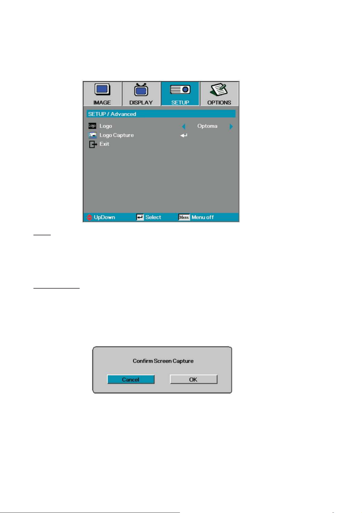
6-5. Logo Advanced
Logo
Select the screen to display during startup.
Optoma—the supplied default startup screen.
User—customized screen capture using the Logo Capture function.
Logo Capture
Capture a displayed screen to use as the startup screen.
1. Display the desired screen on the projector.
2. Select Logo Capture from the Advanced menu.
A
confirmation
screen displays.
3. Select OK. Screen capture in progress.
Screen capture succeeded displays. The captured screen is saved as User
in the Logo menu.
Company Confidential Optoma___________________ Delta________________
90
2008/09/17
Page 91
Delta Elec. Inc. ES520 & EX530 ver.02
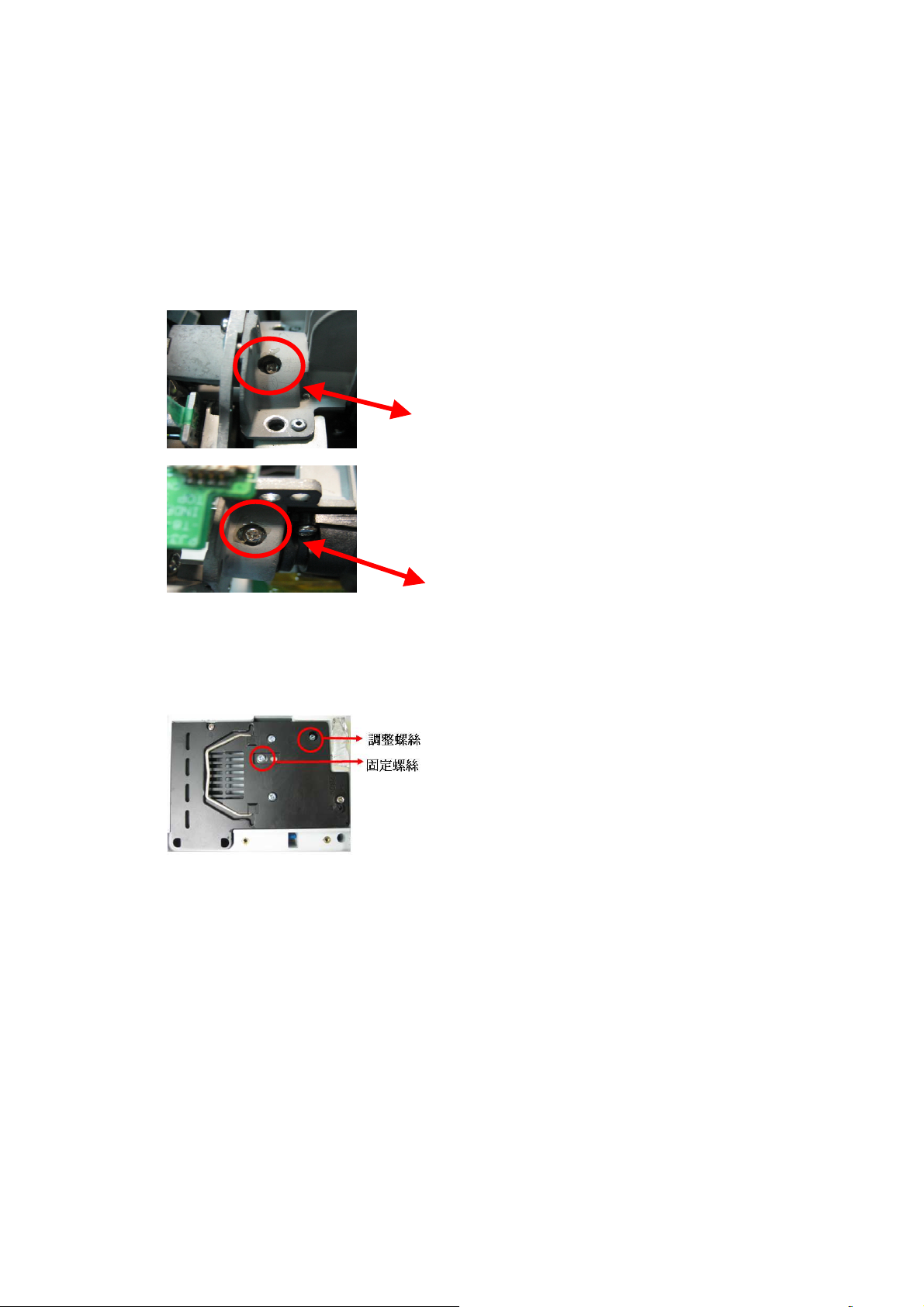
1. Adjust the hexagonal screw in order to right and lift side
the down side of full white
Loosed the fixed screw, CL200 is putted on the left corner of
, to adjust
7. Color Border Adjustment
Step 1 : Adjust integration rod screw to eliminate color edge @ White pattern
color border disappeared. (Enable just disappearing of
left side color border on the full white pattern)
Screw
Screw 1
1
ScrewScrew
1 1
2. Adjust the hexagonal screw in order to up and
down side color border disappeared. By the color
border is margin value on
pattern. (Enable just disappearing of down side
color border on the full white pattern)
Screw 2
Step 2 : Adjust lamp module angle to set the maximum brightness measured by CL200
=> Adjusted screw.
=> Fixed screw.
Company Confidential Optoma___________________ Delta________________
91
the screen(When full set is putted upside down
the adjusted screw gets the highest luminance value then
fixed the screw in the moment.
)
2008/09/17
Page 92
Delta Elec. Inc. ES520 & EX530 ver.02
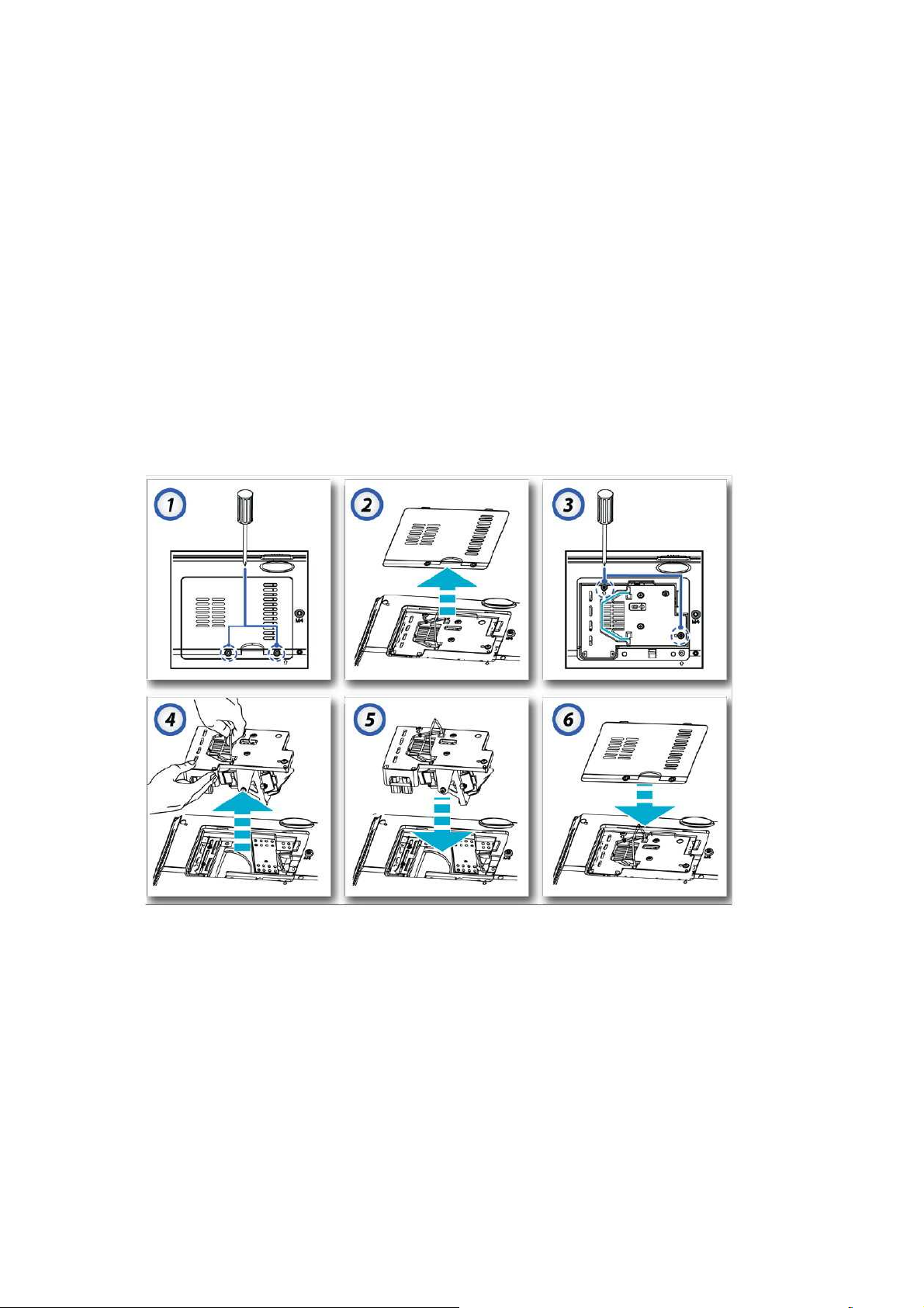
8. Projection Lamp
8-1. Replacing the Projection Lamp
The projection lamp should be replaced when it burns out. It should only be replaced with a
certified replacement part, which you can order from your local dealer.
Important:
1.
The lamp contains a certain amount of mercury and should be disposed according to local
ordinance regulations.
2.
Avoid touching the glass surface of the new lamp: Doing so may shorten its operation life.
Warning:
Be sure to turn off and unplug the projector at least 30 minutes before replacing the lamp.
Failure to do so could result in a severe burn.
1. Loosen the two captive screws on the lamp compartment cover.
2. Remove the lamp compartment cover.
3. Remove the two screws from the lamp module.
4. Lift the module handle up and pull firmly on the module handle to remove the lamp module.
5. Insert the replacement lamp and push down
Tighten the
captive screws to hold the lamp in place.
firmly.
6. Replace the lamp compartment lid and tighten the captive screws.
Company Confidential Optoma___________________ Delta________________
92
2008/09/17
Page 93
Delta Elec. Inc. ES520 & EX530 ver.02
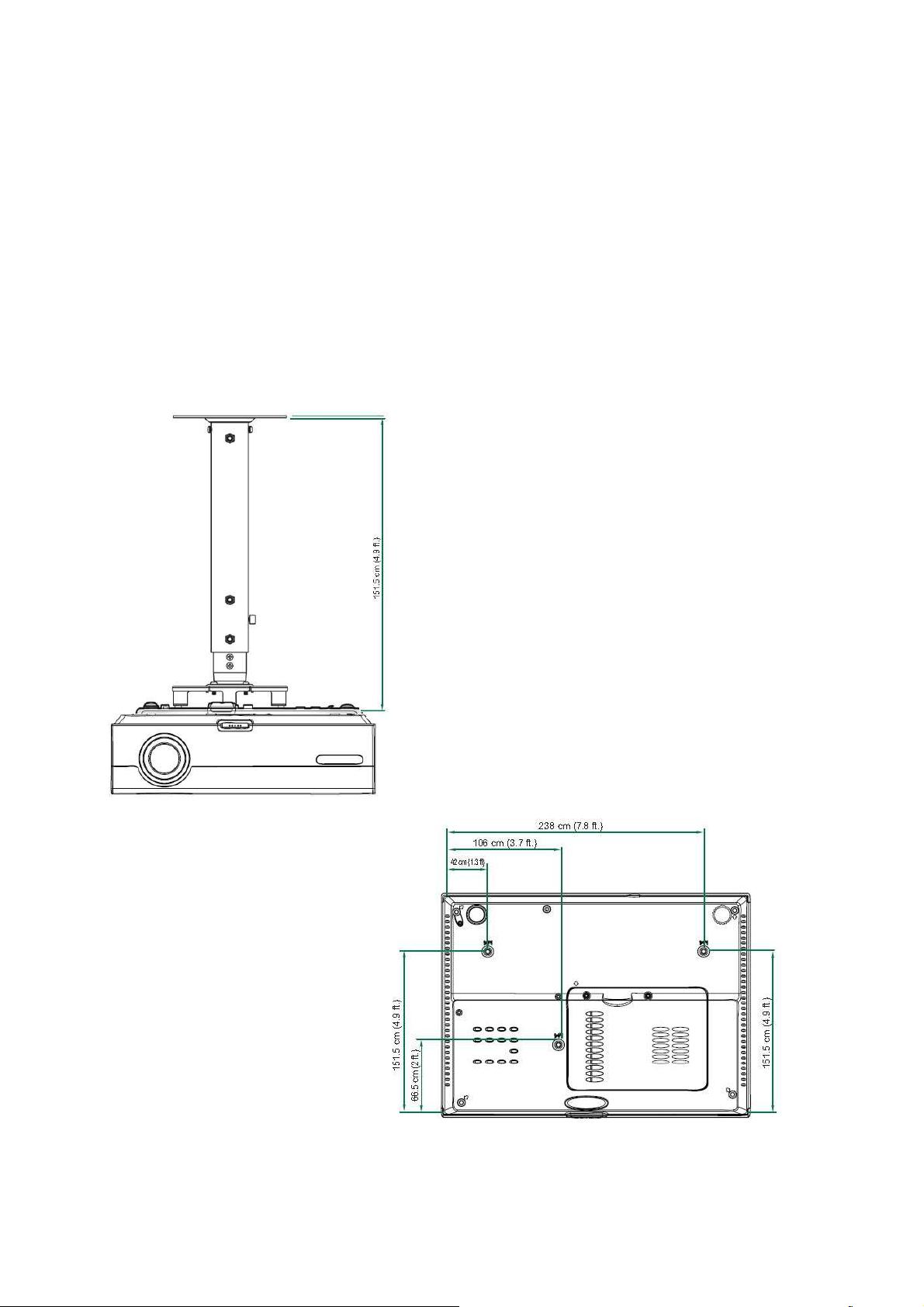
8-2. Ceiling Installation
To prevent damage to your projector please use the recommended mounting package
for installation.
If you intend to use a third party ceiling mount, ensure that the screws meet the
following specifications:
1.Screw Type: M4
2.Maximum screw length: 10 mm
3. Minimum screw length: 7.5 mm
Refer to the following diagram to ceiling mount the projector.
Company Confidential Optoma___________________ Delta________________
93
2008/09/17
Page 94
Delta Elec. Inc. ES520 & EX530 ver.02
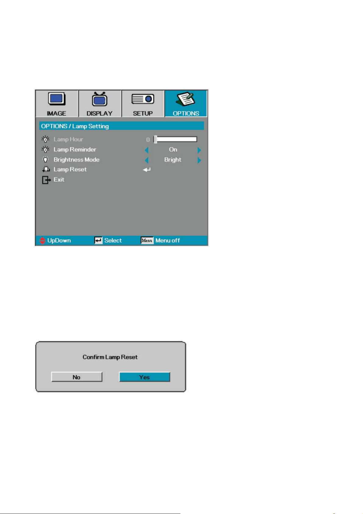
8-3. Lamp Setting
Lamp Reset
After replacing the lamp, reset the lamp counter to accurately reflect the
new lamp’s life span.
1. Select Lamp Reset.
A
confirmation
2. Select Yes to reset the lamp counter to zero.
screen displays.
Company Confidential Optoma___________________ Delta________________
94
2008/09/17
Page 95

Delta Elec. Inc. ES520 & EX530 ver.02
9. Cleaning
9-1. Cleaning the Lens
You can purchase optic lens cleaner from most camera stores. Refer to the following to clean
the projector lens.
1.
Apply a little optic lens cleaner to a clean soft cloth.
(Do not apply the cleaner directly to the lens.
)
2. Lightly wipe the lens in a circular motion.
Caution:
1.
Do not use abrasive cleaners or solvents.
2.
To prevent discoloration or fading, avoid getting cleaner on the projector case
9-2. Cleaning the Case
Refer to the following to clean the projector case.
1. Wipe off dust with a clean dampened cloth.
2. Moisten the cloth with warm water and mild detergent (such as used to wash dishes), and
then wipe the case.
3. Rinse all detergent from the cloth and wipe the projector again
Caution:
To prevent discoloration or fading of the case, do not use abrasive alcohol-based cleaners.
Company Confidential Optoma___________________ Delta________________
95
2008/09/17
Page 96
Delta Elec. Inc. ES520 & EX530 ver.02
*When dust and fingerprints, etc. are on the lens surface, use
iling
*In case of dust in suction or exhaust holes or the interior,
nd use air to remove the dust from
10. SERVICE NOTE
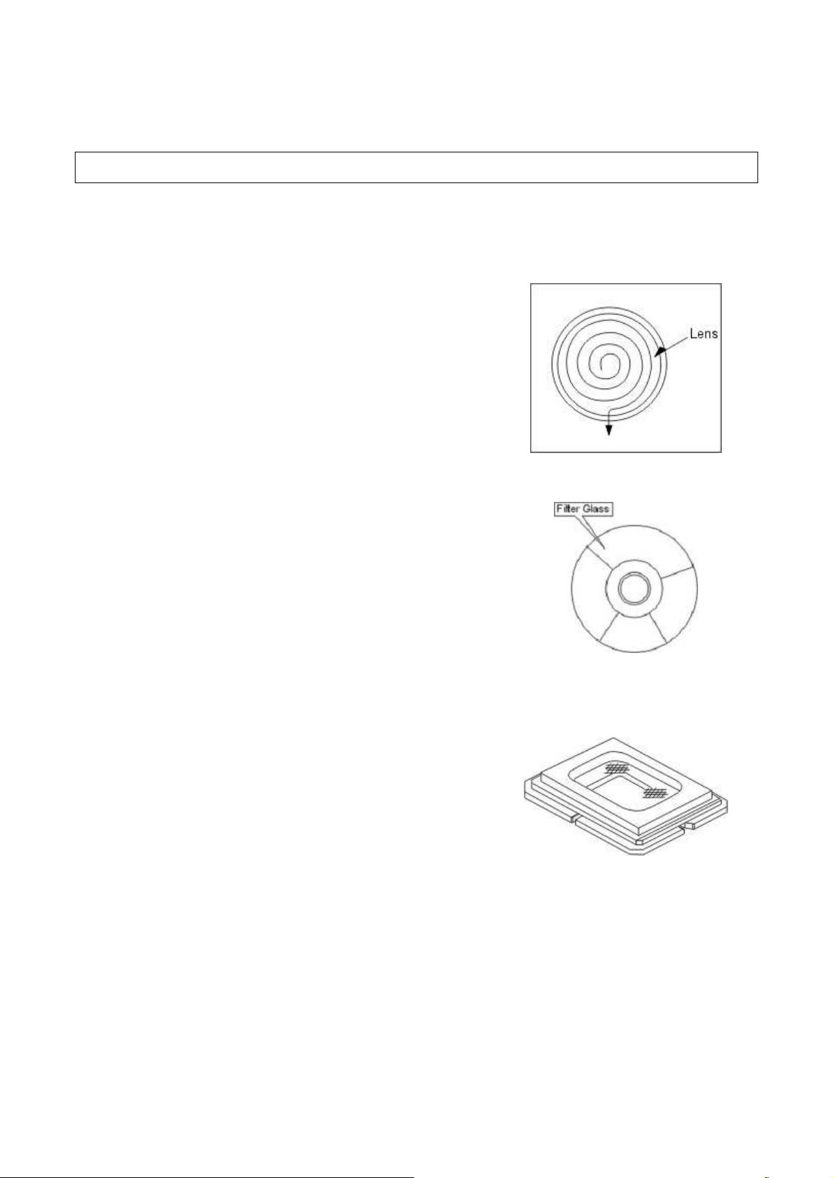
10-1. Service Note Description
Carry out cleaning of the main unit and interior when replacing
the lamp or making inspections.
The glass cleaner used with the following parts is as follows.
1) Cleaning the Projection Lens
the designated glass cleaner to remove as shown in the figure
at the right. For fingerprints and other soiling that are difficult
to remove with a dry cloth, use a designated glass cleaner
which has been moistened in water and then use a dry cloth
to dry it off.
*The projection lens surface has a special coating. Do not use
detergents or solvents on the surface.
2) Cleaning the Color Wheel Assy
*The color filter is made of thin glass. Be very careful when
handing the filter.
*In case of fingerprints, etc. on the surface, clean in the same
way as the projection lens unit as described in item 1). Do not
use detergents as this could cause peeling of the color filter.
3) Cleaning the DMD
*The DMD surface is glass and can be cleaned. However, avoid
scratches as these can have a direct influence on the image.
*In case of dust on the DMD surface use an air cleaner ( with a
device to prevent static, if possible) to clean off the surface.
*In case of fingerprints, etc., add a small amount of water to the
designated glass cleaner and wipe off in one direction. Then
use the designated dry glass cleaner to wipe off in the same
direction.
*Do not use absolute alcohol or other substances that could
leave streaks after drying.
4) Cleaning the Reflecting Mirror
*Be careful not to touch the reflecting mirror. The surface is
composed of vapor deposition silver and touching it directly
with the hands can lead to burnishing.
*Do not clean other than with air.
5) Cleaning the Main Unit
*Clean with a soft fuzz-free cloth. In case of severe soiling, use
a well-wrung cloth dipped in a neutral agent to remove so
and then finish with a dry cloth.
*Do not clean with thinner, benzene or similar agents as this
could lead to deterioration or peeling of paint.
disassemble the main unit a
the inside.
Company Confidential Optoma___________________ Delta________________
96
2008/09/17
Page 97

Delta Elec. Inc. ES520 & EX530 ver.02
10-2. Power & READY LED Blink Code Message
LED Error Messages
SYSTEM STATUS POWER (LED)
TEMP (LED) LAMP (LED)
Lamp Ready Flash OFF OFF
Start ON OFF OFF
Cooling Flash OFF OFF
Over Temperature OFF ON OFF
Thermal Break Sensor error
4 blinks OFF 4 blinks
Lamp error OFF OFF ON
Lamp Fan error 6 blinks OFF 1 blinks
Power Fan error 6 blinks OFF 2 blinks
Blower Fan error 6 blinks OFF 3 blinks
Case Open 7 blinks OFF OFF
DMD error 8 blinks OFF OFF
Color wheel error 9 blinks OFF OFF
Company Confidential Optoma___________________ Delta________________
97
2008/09/17
Page 98
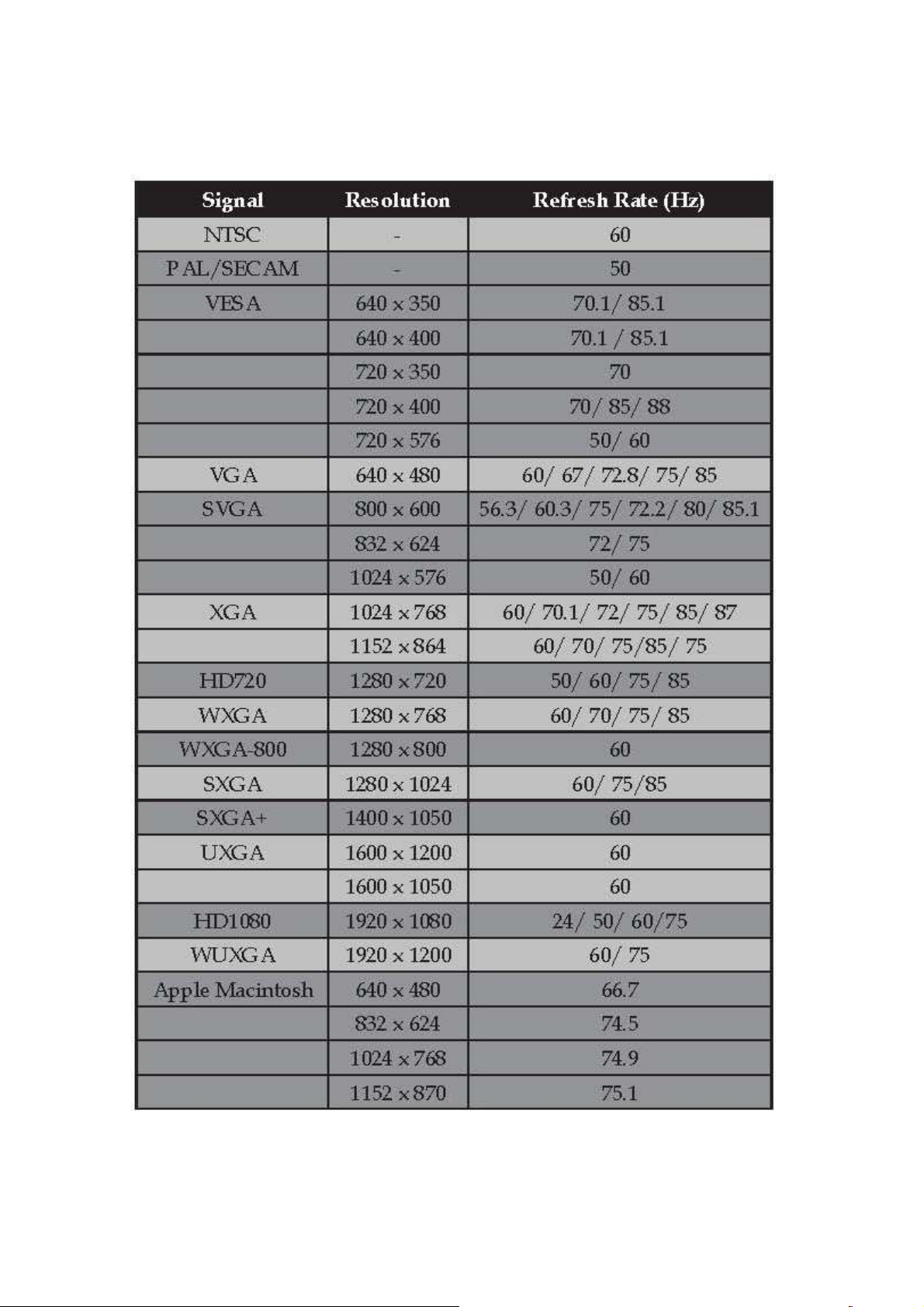
Delta Elec. Inc. ES520 & EX530 ver.02
10-3. Factory Preset Display Modes
Company Confidential Optoma___________________ Delta________________
98
2008/09/17
Page 99
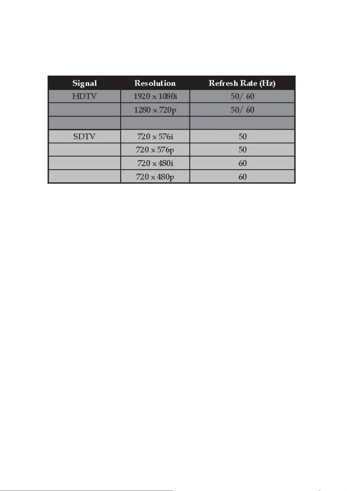
Delta Elec. Inc. ES520 & EX530 ver.02
Company Confidential Optoma___________________ Delta________________
99
2008/09/17
Page 100

Delta Elec. Inc. ES520 & EX530 ver.02
11. Spare part list
Ver.02 Feb-26, 2008
ITEM TYPE DESCRIPTION Q'ty
P/N
KEY PARTS
1 Cover TOP COVER PC+ABS 945VB WHITE (ES520) 1 3392056802
2 Cover TOP COVER PC 945VB WHITE (EX530) 1 3392077001
3 Cover BTM PC 945VB BLK 1 3392057704
4 Cover CASE BACK ASSY DP-2512 1 3398040101
5 Cover LAMP COVER PC 945VB BLK 1 3392057201
6 Button BUTTON ABS 94V0 WHITE 1 3392057001
7 Hook HOOD FOCUS ABS 94V0 WHITE 1 3392074300
8 Foot FOOT RING PC 94V0 BLK 1 3392057400
9 Foot HANDLE POM 94V0 40.4*10.6 BLK 1 3470907000
10 CAP LENS CAP PC 94V0 LIGHT SMOKE GRAY 1 3392076400
11 Fan DC FAN ASSY NFB0712M-SM02 L45/10 70 B 1 3620712511
12 Fan DC FAN ASSY BUB0612HB-SM03 L165/140 60 S 1 3622607311
13 Fan DC FAN ASSY AUB0712MB-R00 L50/20 70 S 1 3622701811
14 Board
PWB ASSY MAIN BOARD J5P-LOW COST (ES520) 1 5600600713
PWB ASSY MAIN BOARD J5P-LOW COST (EX530) 1 5600600785
15 Board PWB ASSY IR BOARD J5P-LOW COST 1 5600600721
16 Board PWB ASSY POWER BOARD J5P-LOW COST 1 5600600722
17 Ballast LAMP DRIVER 180W PULSE PT VIP O3 MID 1
0990077200
18 J5P 0.55" SVGA MULTI THREAD FIX LENS (ES520) 1 5811100434-S
Optical
19
J5P 0.55" XGA MULTI THREAD ZOOM LENS (EX530) 1 5811100432-S
20 Lamp LAMP MODULE J5P PN220 ASSY DP-3520 1 5811100256-S
COMMON PARTS
21 Carton CARTON PAPER 283*188*354 1 3513598000
22 Cable CABLE FFC L160 WHITE 1 3081506600
23 Switch SWITCH ASSY J5P5.6LB 1 3606008901
24 Board PWB ASSY KEYPAD BOARD J5P-LOW COST 1 5600600720
Company Confidential Optoma___________________ Delta________________
100
2008/09/17
 Loading...