

Page 1
Optoma Asia Corporation
5F., No 108, Minchiuan Rd., Xindian City, Taipei 231
Tel: 886-2-2218-2360
Fax: 886-2-2218-2313
www.optoma.com.tw
Optoma USA
715 Sycamore Drive
Milpitas, CA 95035 USA
Tel: 408-383-3700
Fax: 408-383-3702
www.optomausa.com
Optoma Europe Ltd.
42 Caxton Way
The Watford Business Park
Watford Hertfordshire WD18 8QZ UK
Tel: +44 (0) 1923 691 800
Fax: +44 (0) 1923 691 888
www.optoma.co.uk
ISO9001:2000
International Certification
Instruction Manual for Smart Controlled Screen
Thank you for purchasing a Optoma projection screen.
Before use, please read instructions carefully. After installation, store instructions for future reference.
Page 2
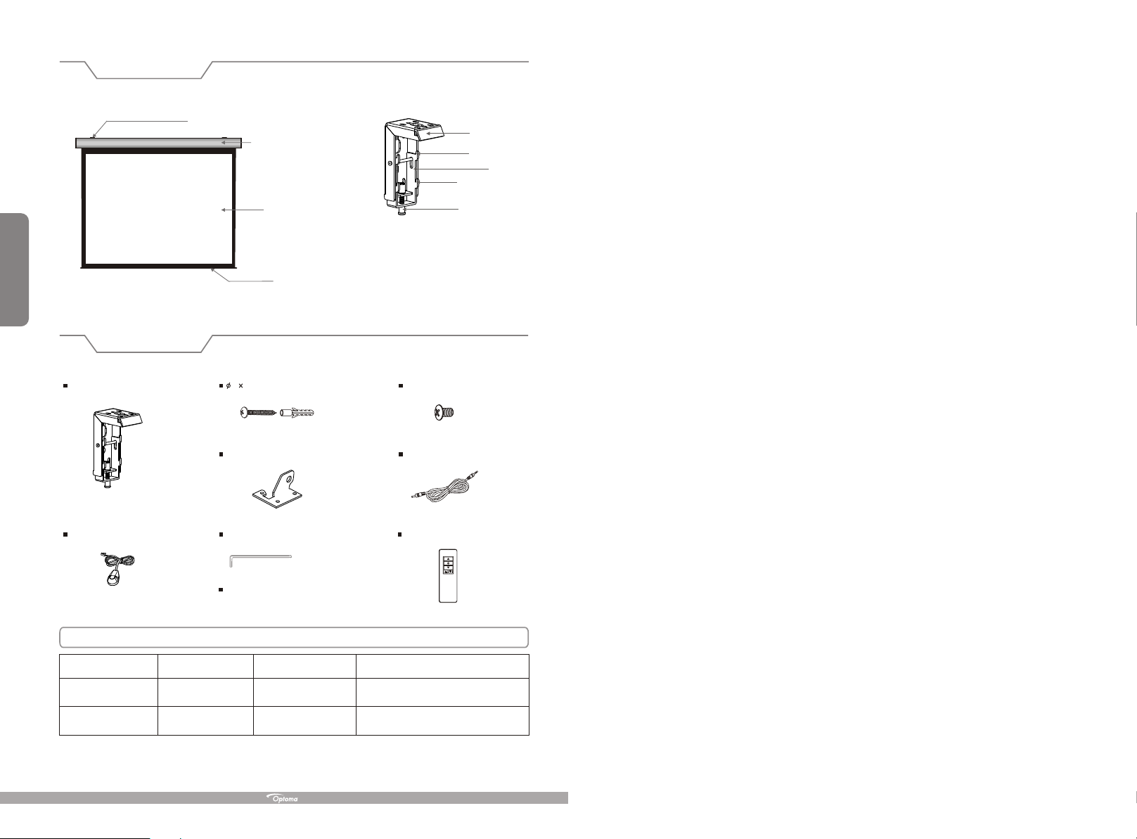
Description
Floating wall bracket
Aluminum casing
Top panel
Up buckle
Baffle
Down buckle
1
Accessories
Floating wall bracket (2pcs)
External IR Receiver (1 )pc
Screen fabric
Bottom rod
5 40mm Tapping screw & cap (8sets)
Ceiling hanger (2pcs)
Allen key (1pc)
Instruction mannual (1pc)
Fixing screw
M5x10 Screw (6pcs)
Trigger line ( 1pc )
Rem
ote
Con
troller
(1pc
)
Optoma Motorized Screen
Voltage (V) Frequency (Hz) Watts (W)
230V/240V(EU)
120V/100V(US)
50Hz/60Hz
50Hz/60Hz
90W/80W
90W/80W
Application
Applies up to 120" motorized screens
Applies up to 120" motorized screens
Page 3

Warnings
The ceiling or wall used for fixture installation must be secure to prevent the screens from falling.
While installing electrical motors, please hire professionals or your local dealer to ensure safety. A misconnection
may lead to fire or leaks.
Make sure the Fixing screw be fastened when using the wall bracket, to avoid any damage.
Keep all infrared wireless products away from fluorescent lighting as it may cause malfunctions.
Please read the following as any damage to the screen surface will affect the quality of the picture:
1.Avoid contact or touching the screen surface as it may cause scratches or tears.
2.Do not write or draw on the surface.
3.Clean the screen with a soft cloth and lukewarm water. Do not use any detergent or cleaning products.
Roll up the screen after every use. Ensure that the screen is level when installing; do not pull on the sides or fold
the screen.
To prevent unnecessary damage, the operating and maintenance of the screen should be done by adults.
Installation
Take out all the parts from the packaging and follow the accessory guideline to ensure you have all parts.
There are three installation measures for this product, namely wall mounting, ceiling mounting and ceiling hang. The
installed distance can be changeable up to your needs via adjusting the slipper block, while the ideal position is the
mounting bracket is at its nearest point to the end cap, which can reduce unnecessary vibration or noise.
Floating wall bracket installation
1. Choose screws for mounting according to wall material. ( Tips: Wood screws for wood wall, and Tapping screws
for concrete wall.)
2. Mount the brackets onto the wall, assuring they are at the horizontal level. (Tips: draw an erasable level line when
mounting the brackets) (Figure 1) Here below are the details:
9
Ignoring the safety warnings may
lead to injuries and/or damaging
the product.
Do not connect any electrical
attachments or remote controls.
Please contact your local dealer for
repair s or maintenance. Please contact
our company if you have any further
questions. Avoid taking apart the
fixtures yourself. Loose parts may
cause the screen to fall.
Do not take apart and replace with unknown parts. If there are any problems, please contact your local dealer.
Product specifications are subject to change.
Fixtures should be installed in a secure
place to avoid accidents or the screen
falling.
Roll up the screen after every use.
Leaving it hanging for a long period
of time may cause the fabric to loosen.
Refrain from hanging anything on t he
screen as it may cause the scree n to
fall.
Figure 1
Installation Steps
a) Wood wall and ceil ing installation: Drill in the 5 x 40 screws through the appropriate holes in the bracket
( Figure 2-3 ).
b) Drywall and ceiling and installation: Install the anchors and drill in the 5 x 40
( Figure 4-5).
bracket holes.
Wood wall installation
Wood ceiling installation
Concrete wall installation
screws into the appropriate
Concrete ceiling installation
2
Figure 2 Figure 3
Figure 4 Figure 5
Page 4

3. Loose the Fixing screw to lower down the all the way. ( Figure 6-7 )Baffle
To avoid overheating the motor, do not continually retract and lower the screen for more than 3 minutes.
If the motor overheats, it will need a cool down for at least 2 minutes. The motor does not need any lubricants.
The drop andretract limit of the screen is factory preset to an optimal configuration. Please ask your local
dealer or professionalto adjust settings to avoid damaging the motor.
3
Fixing screw
Figure 6 Figure 7
4. When mounting the screen onto Floating wall brackets, make sure the Up groove and the Down groove
on the housing match with the Up and the Down on the bracket seperately. ( Figure 8-9 ). buckle buckle
Up groove
Down groove
Figure 8 Figure 9
5. Fasten the Fixing screw on the bracket, to fix housing tightly onto the brackets.( Figure 10-11 )
Baffle
8
Adjust top black border up/down limit use Strew Adjuster A:
Turn clockwise to decrease top black border, turn anti clockwise to increase top black border.
Adjust bar height up/down limit use Strew Adjuster B:
Turn clockwise to increase bar height, turn anti clockwise to decrease bar height.
Remarks: Please use the provided Allen key to adjust the screen.
Please use the above with care, and only adjust in small increments i.e. one turn at one time.
Always check each adjustment once done to make sure you do not over adjust.
If you wish to adjust both top bar and top black border, only do one at a time and then check if correct.
Figure 10 Figure 11
Page 5

How to use Trigger
1. Insert one end of the signal cable into the jack of the handle controller, and the other end into the
DC5V-12V output hole of the projector .
2. Press the control switch of the handle controller to the location.
3
. Switch Manual/Remote Control Button to position "1" (manual stalls).
4. When running the projector, the screen will spread the fabric automatic by synchronous; when closing the
projector, screen will be back automatic by synchronous too.
5. If you don't need to use the t , please draw off the burst line directly, then control it by your hand.
Control:
Trigger
(Figure 22-23)
" "
rigger control
Ceiling hang installation
To choose the tapping screws with hanger or other screws with hanger (unprovided) according to ceiling material.
(Tips: Wood screws 5 x 40 for wood ceiling and tapping screws for concrete wall.)
1. To drill two same holes with an electric drill horizontally with wall, then fasten hangers(unprovided) onto the
ceiling. ( Figure 12 )
A
7
Figure 22 Figure 23
How to use External Control (Central Controller or RS232/USB):
1. Turn the manual/IR remote control switch to position "0" (remote control stalls)
2. Plug one side of the signal cord into the computer output jack at left side of the screen's end cap, the other side
of the singal cord to plug into the jack of Central Controller or computer RS232/USB
Control, an Adapter is necessary to be connected with, the Adapter is not in the accessory package)
and then you can control up/pause/down of the screen via Central Controller or computer.
Figure 24 Figure 25
(Note: in order to use RS232
(Figure 24-25),
How to use IR Remote Control
1. Turn the manual/IR remote control switch to position "0" (remote control stalls)
2. Use the controller if the IR window is not blocked (Figure 26)
3. Use external IR Receiver if the IR window is hidden (by installation) or blocked (Figure 27)
1
Figure 12
2. Use M5 x 10 screws in the accessory package to fix the ceiling hanger into wall bracket, make sure the
tightening screws on wall bracket are fixed tightly. ( Figure 13-14)
Figure 13 Figure 14
3. After fix the ceiling hanger, make sure the up groove and the down groove on the housing match with Up
button and Down button on the bracket separately and fasten the fixing screw on the bracket, to fix housing
tightly onto the brackets.( Figure 15-16)
Figure 15 Figure 16
4. After finished step 2 and step 3, check whether wall bracket fix on the housing of screen tightly then you can
hang the screen according to the figure 17.
2
4
Inner IR Receiver
Window
Figure 26 Figure 27
External IR Jack
Figure 17
Page 6

Instructions
Operation Instruction
5
MICRO-UP
1GD IRan
LED
remote controller
UP
STOP
DOWN
MICRO-DOWN
Controller button instruction
1.To raise screen press "UP .
2.To hold screen at desired position press STOP .
3.To lower screen press DOWN .
"
""
""
4. To raise the screen little at your desired position press MICRO-UP
5. To lower the screen little at your desired position press MICRO-DOWN
Caution:
The shortest distance between receiver and controller is 0.5 meter.
1.
.Controller work within 30 degree away horizontally from t he cen ter of recei ver
2 will
point within 8 meters from the screen.
.The controller not work the signal was coveredby something.
3 will if
.Keep the controller far away from high temperature and humid situation.
4
.Please change the battery when the signal is weak.
5
.Please take the battery out if the controller was not being used for long time.
6
.Please choose the same type battery as original supplied.
7
How to install the battery:
1.Turn the controller around, push to open the cover as guide arrow.
2.Put the battery in according the guide of cathode and anode.
3.Close the cover.
Connecting to the external power:
ear off the glue cloth fixed on the bottom rod,ensure the bottom rod is not stuck by the casing.
1. T
2. Switch on the power (within stated voltage).
How to use Manual/Remote Control Switch Button: (Figure 18)
The screen has four kinds of optional control methods: IR Remote Control, Manual Control, Trigger Control,
External Control (Central Control or RS232/USB). When switching the Manual/Remote Control Switch
Button to position "1", you can use Manual Control or Trigger to control up/pause/down of the screen. When
switching to position "0", you can use IR Remote Control or External Control (Central Controller or Rs232/USB)
to control up/pause/down of the screen.
Connecting External IR
Trigger Jack
Manual/Remote Control
Switch Button
Figure 18
Computer Output
Jack
Manual Control
LAN
Central Controller
Projector
How to use manual switch control:
1. Switch Manual/Remote Control Button to position "1" (manual stalls).
Turn the switch to position to lower the screen
2. " " ; it will come down slowly. When it is all the way down,
it will stop automatically (Figure 20) .
3. Turn the switch to " " to retract the screen; it will go up into the metal casing. When it is all the
way up, it will stop automatically (Figure 21).
4. To stop any time while the screen is in motion, turn the switch to 0.
position
6
Manual
Control
Figure 19 Figure 20 Figure 21
 Loading...