

Page 1
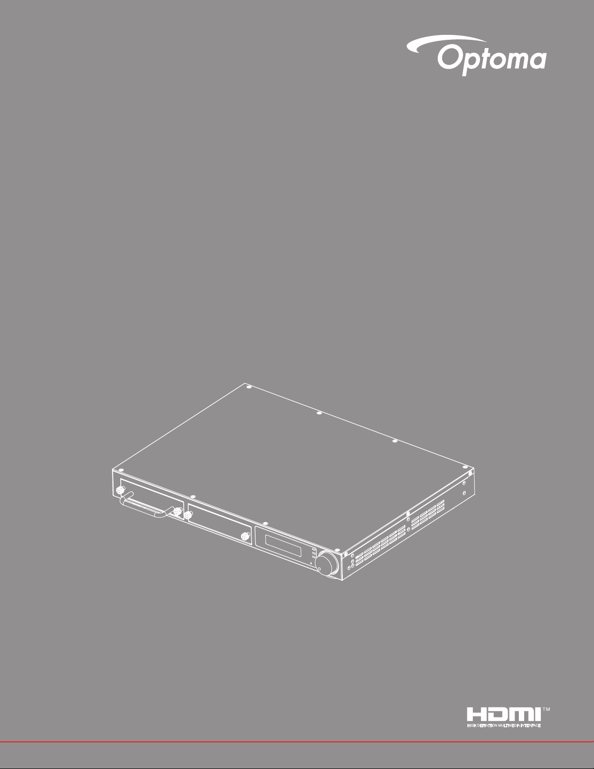
4K Cropping Box
User manual
Page 2

Table of Contents
1 INTRODUCTION ....................................................................................................................................................3
2 FEATURES ............................................................................................................................................................3
3 SPECIFICATIONS .................................................................................................................................................4
3.1 CS200TMainBoxSpecication .....................................................................................................................4
3.2 CS200T Module & Model List .........................................................................................................................5
4 CONNECTION DIAGRAM .....................................................................................................................................7
5 PANEL DESCRIPTIONS .......................................................................................................................................8
5.1 Front Panel .......................................................................................................................................................8
5.2 Rear Panel ........................................................................................................................................................9
6 OPERATION APPROACH ...................................................................................................................................10
6.1 Knob Control..................................................................................................................................................10
6.1.1 LCM Menu Tree ..............................................................................................................................................11
6.1.2 Initial Page .....................................................................................................................................................12
6.1.3 Startup Page ..................................................................................................................................................12
6.1.4 Main Page Flow..............................................................................................................................................12
6.1.5 Information Page ...........................................................................................................................................13
6.1.6 Network Page .................................................................................................................................................14
6.1.7 Video Page .....................................................................................................................................................15
6.1.8 Audio Page .....................................................................................................................................................15
6.1.9 Cropping Page ...............................................................................................................................................16
6.1.9.1 Layout & Overlap Description ......................................................................................................................17
6.1.10 Options Page .................................................................................................................................................18
6.1.10.1 Standby and Signal Power On Description.................................................................................................18
7 Regulation & Safety Notices .............................................................................................................................19
2 English
Page 3

1 INTRODUCTION
CS200T Video Processor is dedicated to image cropping application. CS200T is modular design
for exibility and loop out function for high expandability to achieve different applications.
Base on "Everything on LAN" concept, CS200T achieve image blending system installation and
maintenance.
2 FEATURES
● Up to 4K@60Hz input resolution
● Up to 4 ports 1920x1200@60Hz output resolution
● Image Cropping
● Stereo Audio Output and Input
● Audio pass-through or mixer mode to HDMI output ports
● HDMI 2.0 Loop through port for image cascade to next CS200T
● Modular design for cropping/HDBaseT function
● DHCP for IP setting
● Built in Ethernet Switch
English 3
Page 4

3 SPECIFICATIONS
3.1 CS200TMainBoxSpecication
Interface
Input Specication
Interface HDMI
Standard HDMI 2.0, HDCP 2.2
Resolution Up to 4K@60Hz, Support specied resolution
Port Number 1
Loop Out Standard HDMI 2.0, HDCP 2.2
Audio Input Stereo L/R Line In
Output Specication
Interface HDMI / RJ45
Standard HDMI 1.4a, HDCP 1.4 / HDBaseT 1.0
Output Resolution Up to WUXGA@60Hz (1920x1200)
Number 2 (default), can be extended to 4
Audio Output Stereo L/R Line Out
General
Control Interface LAN x 2, RS232, LCM & Knob
LAN Cascade Support, Ethernet Switch inside
Sub-module Qty. 2 Insertion Slots
Cropping Layout 1x2 / 2x2 / 1x3 / 1x4
Overlap Percentage/
Pixel
Power Consumption < 80W @ 100~240V AC
Product Dimension 425x313x44.5 mm (WxDxH)
Note: CS200T can be extended to 4 channels output by using two CRPT-2K modules.
H/V Output resolution pixel* (0~100%)
4 English
Page 5
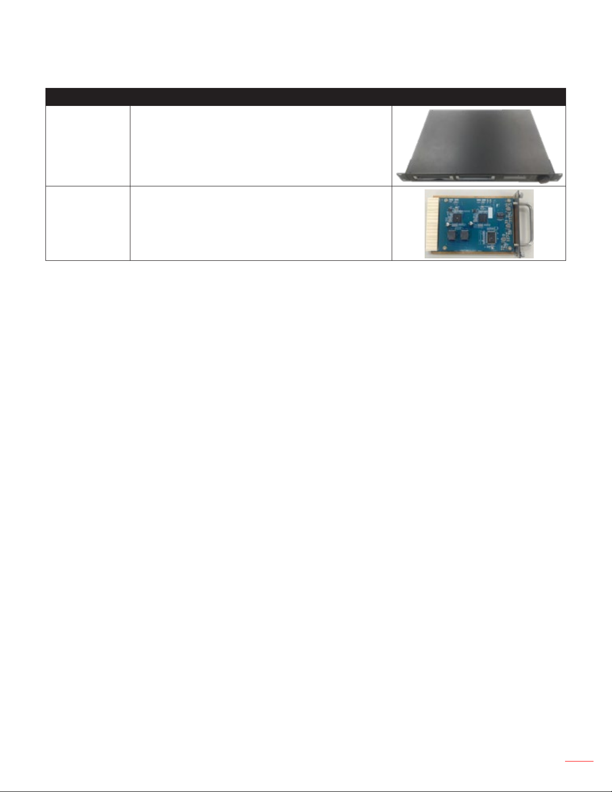
3.2 CS200T Module & Model List
Unit Product Description Note
Main Box Cropping Main Box
CRPT-2K
2K Cropping Module –
HDMI / HDBaseT out (2 CH)
English 5
Page 6
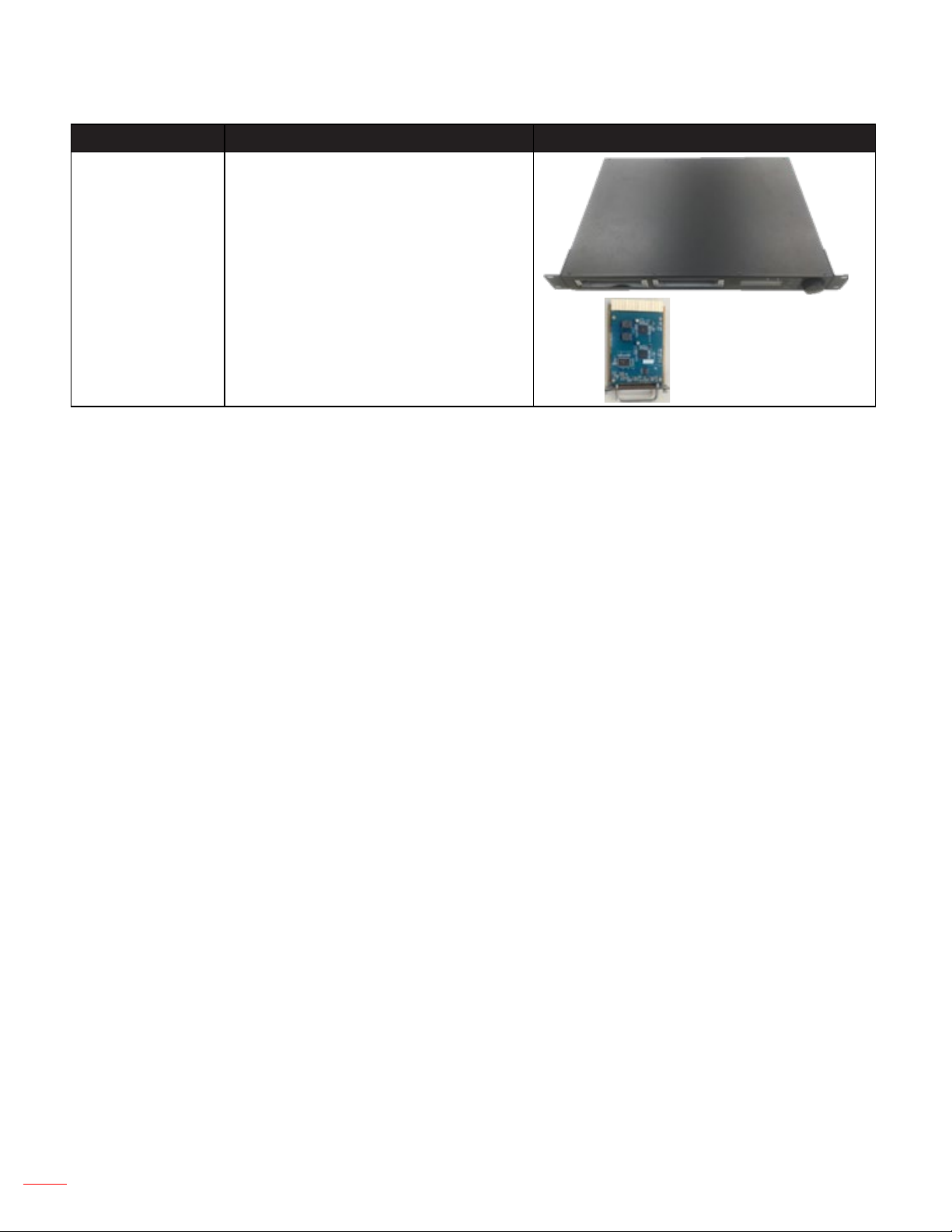
Model Name Description Note
Main Box + 1 x CRPT-2K
CS200T
(For Projector W/ Warping &
Blending function)
CRPT-2K
Note: CS200T can be extended to 4 channels output by using two CRPT-2K modules.
6 English
Page 7
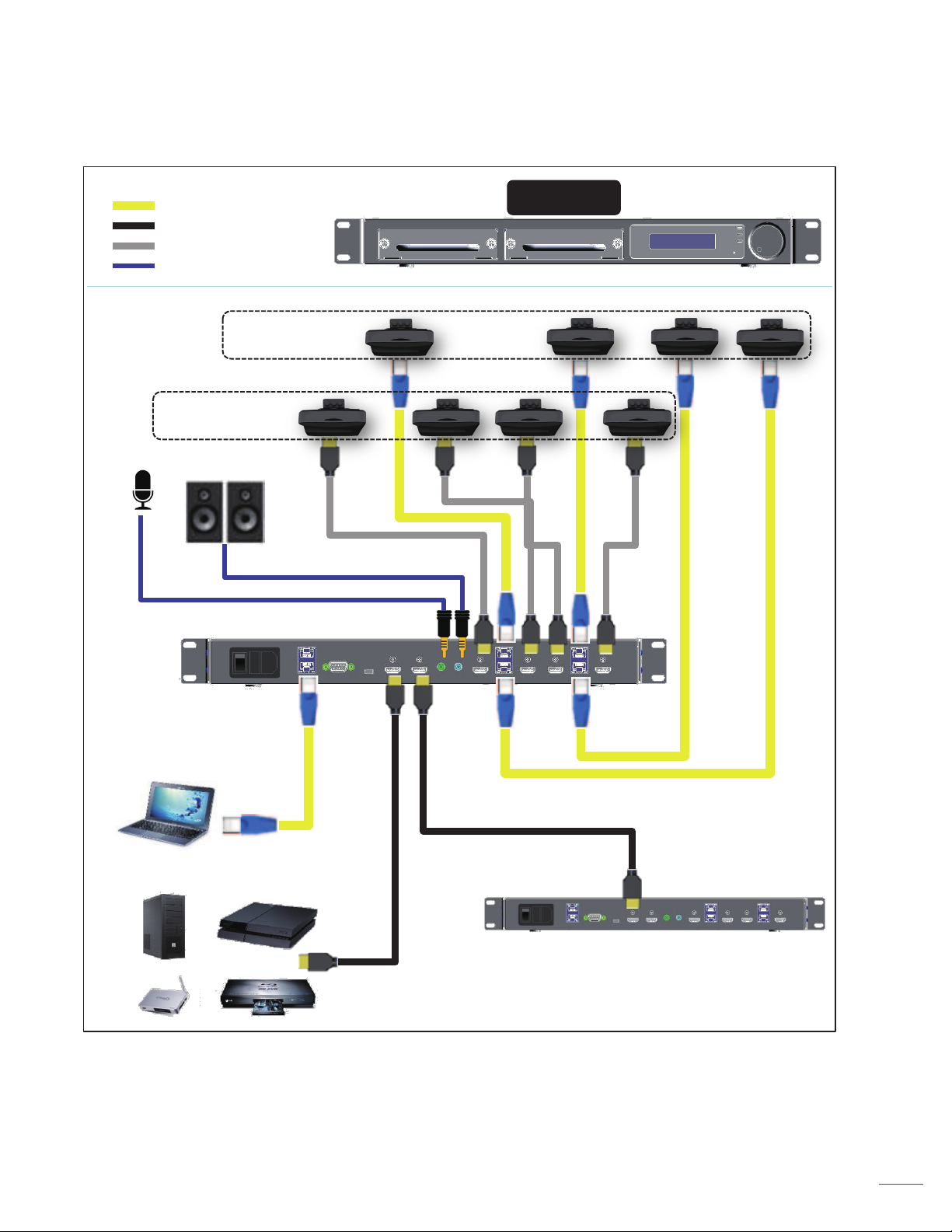
4 CONNECTION DIAGRAM
CAT5E Cable
HDMI 2.0 Cable
HDMI 1.4a Cable
3.5mm Audio Cable
Display Device
Audio Source
Display Device
OR
CS200T
CS200T
Control Unit
4K Source
HDMI 2.0 Cascade
CS200T for more cropping
Note1: CS200T can be extended to 4 channels output by using two CRPT-2K modules.
Note2: CS200T with Ethernet Hub inside for cascading the LAN ports of 2 units of CS200T.
English 7
Page 8

5 PANEL DESCRIPTIONS
5.1 Front Panel
7
1. Knob: Knob with Push Button Switch
2. PWR LED: Power ON LED Indication
3. Slot1 LED: Slot 1 Status LED Indication
4. Slot2 LED: Slot 2 Status LED Indication
5. LCM Display: LCM Display for Setting and Information Retrieve
6. Reset Button: System Rest Button
7. Module Slot 1: Slot 1 Position
8. Module Slot 2: Slot 2 Position
8
5
4
2 3
1
6
8 English
Page 9
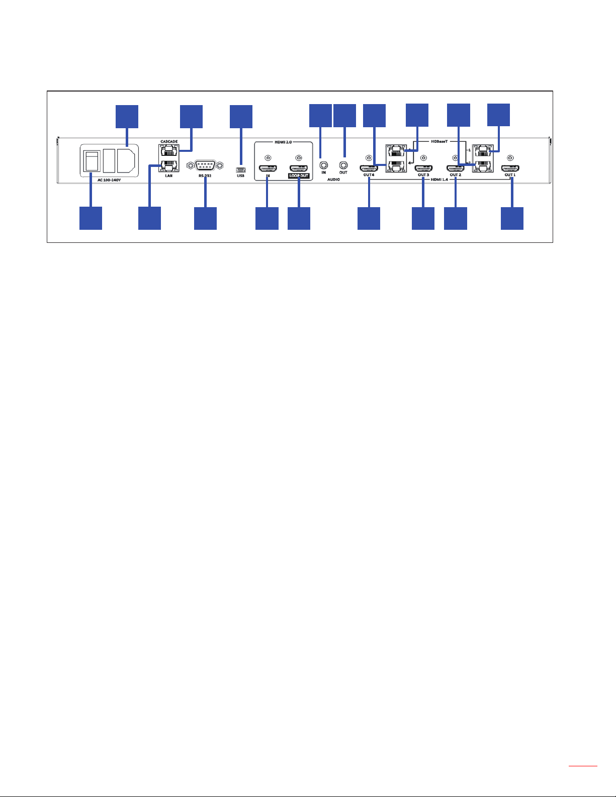
5.2 Rear Panel
15
17 18
20
25
26
24
23
22
21
19
16
12
11
14
10
13
9
9. HDMI Out 1: HDMI 1.4a output port 1, is activated as module plug-in slot 1.
10. HDMI Out 2: HDMI 1.4a output port 2, is activated as module plug-in slot 1.
11. HDMI Out 3: HDMI 1.4a output port 3, is activated as module plug-in slot 2.
12. HDMI Out 4: HDMI 1.4a output port 4, is activated as module plug-in slot 2.
13. HDBaseT Out 1: HDBaseT Output Port 1, is activated as module with HDBT Card plug-in slot 1.
14. HDBaseT Out 2: HDBaseT Output Port 2, is activated as module with HDBT Card plug-in slot 1.
15. HDBaseT Out 3: HDBaseT Output Port 3, is activated as module with HDBT Card plug-in slot 2.
16. HDBaseT Out 4: HDBaseT Output Port 4, is activated as module with HDBT Card plug-in slot 2.
17. Stereo audio output: Stereo Audio Output
18. Stereo audio Input: Stereo Audio Input
19. HDMI 2.0 Loop-Through Output: HDMI 2.0 Loop Output Port, connect to next CS200T
20. HDMI 2.0 Input: HDMI 2.0 Input Port, connection with A/V source
21. Mini USB Port: Mini USB Port for Firmware Upgrade
22. RS-232: RS-232 control port, DTE Mode
23. LAN Cascade Port: Ethernet control port for cascade of CS200T
24. LAN Port: Ethernet control port
25. AC Power Inlet: AC 110/220V Power input
26. Power Switch: Power Switch
English 9
Page 10

6 OPERATION APPROACH
!
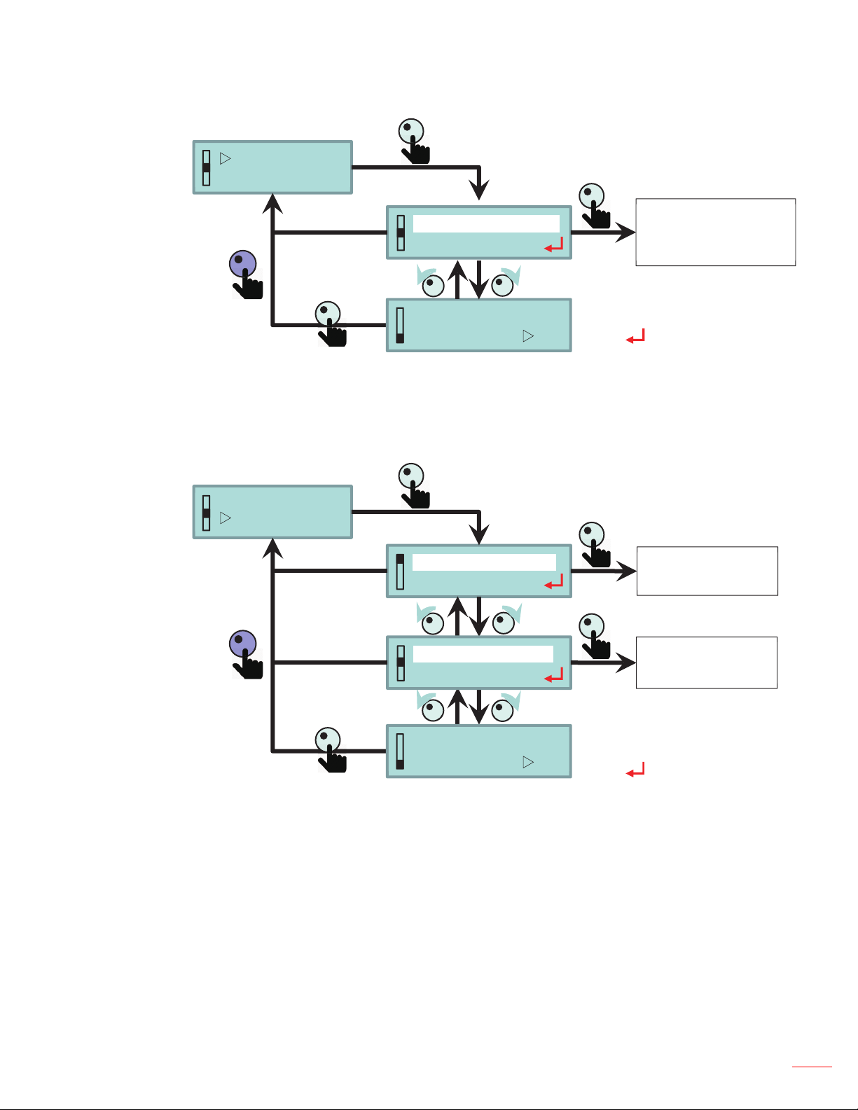
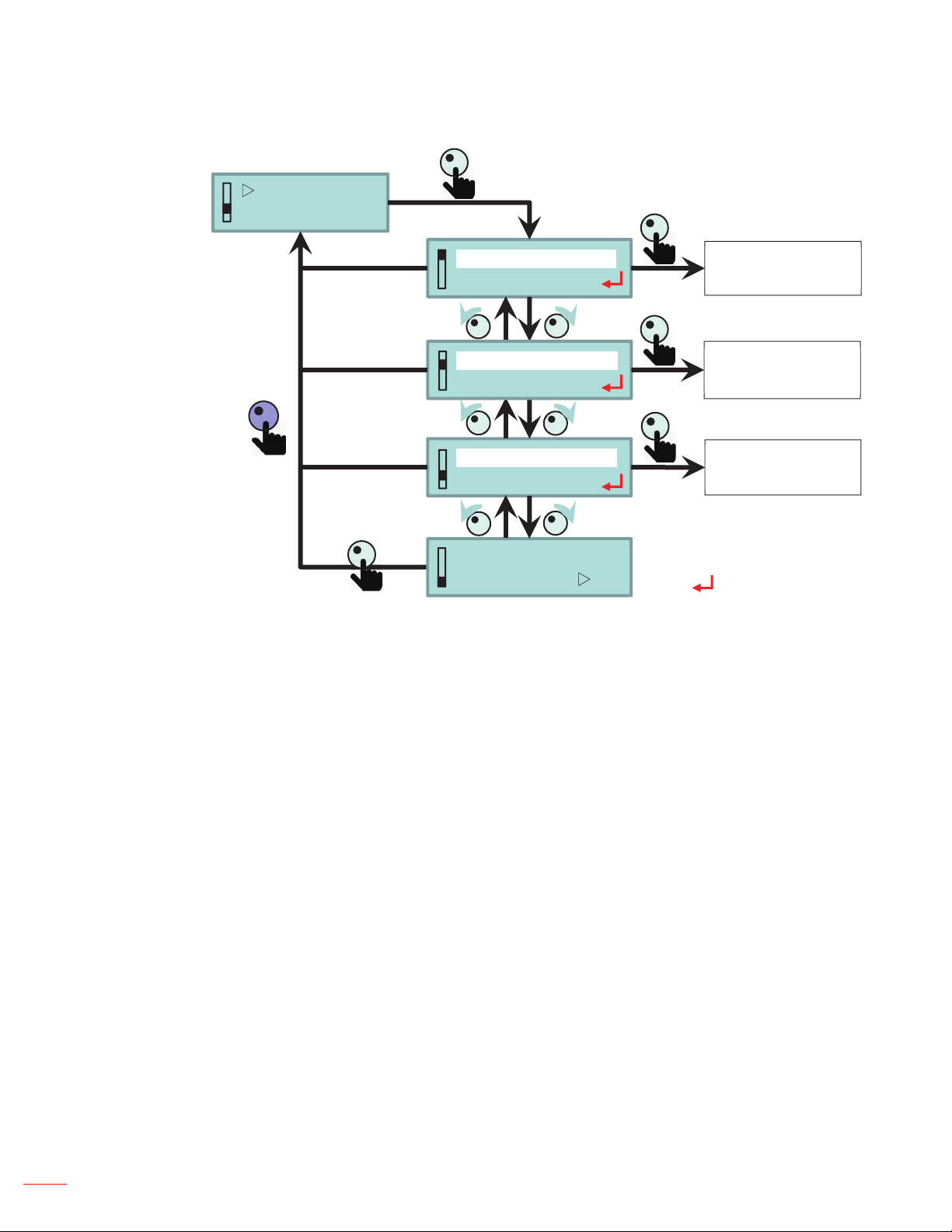
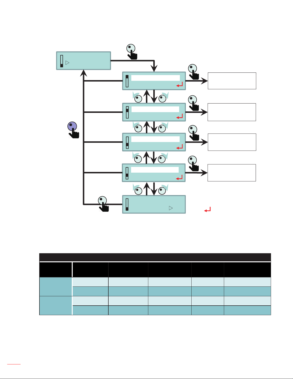
6.1 Knob Control
Icon Description Action
One Push
Two-second Press Back to upper menu
Clockwise Rotation
Anti-Clockwise
Rotation
1. Enter Menu
2. Conrm setting
1. Next Item
2. Value Increment
1. Last Item
2. Value Decrement
10 English
Page 11

6.1.1 LCM Menu Tree
Main level 2nd level 3rd level Default Value Notes
Device Name CS200T Display Only
FW Version Cxx.xx Display Only
Module Name 1 CRP-2K/CRPT-2K/NONE Display Only
Module Name 2 CRP-2K/CRPT-2K/ NONE Display Only
Display Only
Resoluon
example:1024x768@60
INFORMATION
Input Status
EDID Timing 3840x2160 3840x2160
(Resoluon) / No Connecon / Not
Support
No Connecon
NETWORK
VIDEO
AUDIO
CROPPING
OPTIONS
Error Code No Error No Error
Exit
DHCP ON/OFF OFF
IP Address 192.168.0.150 192.168.0.150
Subnet Mask 255.255.255.0 255.255.255.0
Gateway 192.168.0.254 192.168.0.254
MAC 00-50-41-xx-xx-xx Display Only
Exit
Output Timing
Exit
Volume 0~15 8
System Mute ON/OFF OFF
Exit
Layout 1x1/1x2/1x3/1x4/2x2 1x1
H. Overlap 0~1920 (Unit: Pixel)
V. Overlap 0~1080 (Unit: Pixel)
Exit
Factory Reset CANCEL / OK CANCEL
LAN Standby Mode OFF/LAN Standby LAN Standby
LAN Standby Time 0 Min~60Min (Interval 5 Mins) 15 Min
Signal Power On OFF/ON OFF
Exit
1024x768/1280x800/1920x720/
1920x1080/1920x1200
1920x1080
H. pixel of output
ming
V. pixel of output
ming
1. No Error
2. 00000001 ~ FFFFFFFF
Display Only when DHCP
ON
4 pixels scale for all output
ming
4 pixels scale for all output
ming
English 11
Page 12

6.1.2 Initial Page
System Inial. . .
The system will take 10 seconds for initial.
6.1.3 Startup Page
OPTOMA
CS200T_2CH
6.1.4 Main Page Flow
OPTOMA
CS200T_2CH
INFORMATION
NETWORK
INFORMATION
NETWORK
VIDEO
AUDIO
VIDEO
AUDIO
CROPPING
OPTIONS
CROPPING
OPTIONS
12 English
Page 13

6.1.5 Information Page
INFORMATION
NETWORK
Device Name
CS200T
FW Version
C11.00
Module Name 1
CRPT-2K
Module Name 2
CRPT-2K
Input Status
No Connecon
EDID Timing
3840x2160
Error Code
No Error
Exit
English 13
Page 14

6.1.6 Network Page
INFORMATION
NETWORK
DHCP
OFF
IP Address
192 . 168 . 0 . 150
Subnet Mask
255 . 255 . 255 . 0
Gateway
192 . 168 . 0 . 254
MAC
00–50–41–90–1F–6C
ON /OFF
XXX.XXX.XXX.XXXġ
XXX.XXX.XXX.XXXġ
XXX.XXX.XXX.XXXġ
ġ
Exitġ
Enter Selection Page
14 English
Page 15
6.1.7 Video Page
VIDEO
AUDIO
6.1.8 Audio Page
VIDEO
AUDIO
Output Timing
1920 x 1080
ġ
Exitġ
Volume
08
1024x768/1280x800/
1920x720/1920x1080/
1920x1200
Enter Selection Page
0 ~ 15
System Mute
OFF
ġ
Exitġ
ON / OFFġ
Enter Selection Page
ġ
English 15
Page 16
6.1.9 Cropping Page
/
CROPPING
OPTIONS
Layout
1 x 1
H. Overlap
384 ( 20 . 00 x )
V. Overlap
0 ( 0. 00 x )
ġ
Exitġ
1x1/1x2/1x3/1x4
2x2
0 ~ 50% pixelsġ
0 ~ 50% pixelsġ
Enter Selection Page
ġ
16 English
Page 17

6.1.9.1 Layout & Overlap Description
Layout
CH 1 CH 2 CH 3 CH 4
Cropping Input Mapping Overlap Width
1x1
0
(Block) (Block)
0
0
1x2
20%
(Block)
0
1x3
Disable
20%
(Block)
0
1x4
2x2
Custom
0 0
Specied Conguration (Only for AP)
20%
(Block)
20% 20%
Layout 1x1 means output full input image.
Overlap Width will be reset after Layout setting changed or Output timing
changed.
Output port will output solid YELLOW Color as port disabled.
Output port will output solid GREEN color as no valid input timing.
Cropping Setting by AP, Layout state will display “Custom”.
The scale of Overlap Width is 4 pixel and range is 0~100% of image.
English 17
Page 18
6.1.10 Options Page
CROPPING
OPTIONS
Factory Reset
ENTER
LAN Standby Mode
LAN Standby
LAN Standby Time
15 Min
Signal Power ON
OFF
ġ
Exitġ
CANCEL / OK
LAN Standby /
OFFġ
0 ~ 60 Min.
5 Min. Scaleġ
ON / OFFġ
Enter Selection Page
18 English
6.1.10.1 Standby and Signal Power On Description
LCM Menu Wakeup Criteria
Mode
Standby
LAN
Standby
Signal
Power ON
OFF X V V X
ON V V V X
OFF X V V V
ON V V V V
HDMI Input
Valid
RS-232
PWR ON Cmd
Knob
Push
LAN (Telnet)
PWR ON Cmd
Page 19

7 Regulation & Safety Notices
FCC Notice:
This device complies with Part 15 of the FCC rules. Operation is subject to the following two
conditions
(1)This device may not cause harmful interference,
(2)This device must accept any interference receive ; including interference that may cause
undesired operation.
This Equipment has been tested and found to comply with the limits for a Class A digital device,
pursuant to part 15 of the FCC Rules. These limits are designed to provide reasonable protection
against harmful interference when the equipment is operated in a commercial environment.
This equipment generates, uses, and can radiate radio frequency energy and, if not installed
and used in accordance with the instruction manual, may cause harmful interference to radio
communications.
Operation of this equipment in a residential area is likely to cause harmful interference in which
case the user will be required to correct the interference at his own expense.
THIS DEVICE COMPLIES WITH FCC PART 15 AND ICES-003, CLASS A. REFER TO LABEL ON
BOTTOM FOR ADDITIONAL DETAILS.
Notice: Canadian users
CAN ICES-3(A) / NMB-3(A)
The Class A digital apparatus meets all requirements of the Canadian Interference-Causing
Equipment Regulation. Interference-Causing Equipment Regulation.
Cet appareil numerique de la class A respecte toutes les exigences du Reglement sur le materiel
brouilleur du Canada.
CE Notice:
This product is herewith conrmed to comply with the requirements set out in the Council
Directives on the Approximation of the laws of the Member States relating to Electromagnetic
Compatibility Directive 2004/108/EEC.
Warning
- This product must not be used in residential areas.
- This product may cause interference if used in residential areas.
Such use must be avoided unless the user takes special measures to reduce electromagnetic
emissions to prevent interference to the reception of radio and television broadcasts.
KC Notice:
이 기기는 업무용 환경에서 사용할 목적으로 적합성평가를 받은 기기로서 가정용 환경에서 사용
하는 경우 전파간섭의 우려가 있습니다
English 19
Page 20
Optomaglobalofces
For service or support, please contact your local ofce.
USA
Optoma Technology, Inc.
47697 Westinghouse Drive.
Fremont, Ca 94539
www.optomausa.com
888-289-6786
510-897-8601
services@optoma.com
Canada
Optoma Technology, Inc.
47697 Westinghouse Drive.
Fremont, Ca 94539
www.optomausa.com
888-289-6786
510-897-8601
services@optoma.com
Latin America
Optoma Technology, Inc.
47697 Westinghouse Drive.
Fremont, Ca 94539
www.optomausa.com
888-289-6786
510-897-8601
services@optoma.com
Europe
Unit 1, Network 41, Bourne End Mills
Hemel Hempstead, Herts
HP1 2UJ, United Kingdom
www.optoma.eu
Service Tel : +44 (0)1923 691865
+44 (0) 1923 691 800
+44 (0) 1923 691 888
service@tsc-europe.com
Benelux BV
Randstad 22-123 +31 (0) 36 820 0252
1316 BW Almere
The Netherlands
www.optoma.nl
+31 (0) 36 548 9052
Scandinavia
Lerpeveien 25 +47 32 98 89 90
3040 Drammen
Norway
PO.BOX 9515
3038 Drammen
+47 32 98 89 99
info@optoma.no
Norway
Korea
WOOMI TECH.CO.,LTD.
4F,Minu Bldg.33-14, Kangnam-Ku,
seoul,135-815, KOREA
+82+2+34430004
+82+2+34430005
Japan
東京都足立区綾瀬3-25-18
株式会社オーエス
コンタクトセンター:0120-380-495
info@os-worldwide.com
www.os-worldwide.com
Taiwan
12F., No.213,Sec. 3, Beixin Rd.,
Xindian Dist., New Taipei City 231,
Taiwan, R.O.C.
www.optoma.com.tw asia.optoma.com
+886-2-8911-8600
+886-2-8911-6550
services@optoma.com.tw
Hong Kong
Unit A, 27/F Dragon Centre,
79 Wing Hong Street,
Cheung Sha Wan,
Kowloon, Hong Kong www.optoma.com.hk
+852-2396-8968
+852-2370-1222
France
Bâtiment E +33 1 41 46 12 20
81-83 avenue Edouard Vaillant
92100 Boulogne Billancourt,
France
+33 1 41 46 94 35
savoptoma@optoma.fr
Spain
C/ José Hierro,36 Of. 1C +34 91 499 06 06
28522 Rivas VaciaMadrid,
Spain
+34 91 670 08 32
Deutschland
Wiesenstrasse 21 W +49 (0) 211 506 6670
D40549 Düsseldorf,
Germany
20 English
+49 (0) 211 506 66799
info@optoma.de
China
5F, No. 1205, Kaixuan Rd., +86-21-62947376
Changning District
Shanghai, 200052, China www.optoma.com.cn
+86-21-62947375
Page 21

www.optoma.com
 Loading...