

Page 1
DLP® Projector
User manual
Page 2

2
English
Table of Contents
Table of Contents ............................2
Usage Notice ...................................3
Safety Information ...............................3
Precautions .........................................4
Introduction ......................................6
Package Overview ..............................6
Product Overview ...............................7
Main Unit ..............................................7
Control Panel ....................................... 8
Input/Output Connections .................... 9
Remote Control ..................................10
Installation ..................................... 11
Connecting the Projector .................. 11
Connect to Computer/Notebook ........ 11
Connect to Video Sources ................. 12
Powering the Projector On / Off ........13
Powering On the Projector .................13
Powering Off the Projector .................14
Warning Indicator ...............................14
Adjusting the Projected Image ..........15
Adjusting the Projector�s Height ........ 15
Adjusting the Projector�s Focus ......... 16
Adjusting Projection Image Size
(Diagonal) .......................................... 17
User Controls ................................19
Control Panel & Remote Control ......19
Control Panel ..................................... 19
Remote Control ..................................20
IR Remote codes ............................... 22
Structure ........................................... 23
On-screen Display Menus ................23
How to operate ..................................26
Picture ................................................27
Screen ...............................................29
Setting ................................................31
Volume ...............................................33
Options ..............................................34
Options | Laser Settings ....................36
3D ...................................................... 37
LAN .................................................... 38
Multimedia .....................................44
Accessing Multimedia Files ..............44
How to access Multimedia mode ....... 44
Appendices ....................................62
Installing and Cleaning the Optional
Dust Filter .........................................62
MMA Support List .............................63
Compatibility Modes .........................68
VGA Analog ....................................... 68
HDMI Digital .......................................70
RS232 Protocol Function List ............ 72
Regulation & Safety Notices .............74
Ceiling Mount Installation ..................77
Page 3
3
English
Usage Notice
Safety Information
The lightning ash with arrow head within an equilateral triangle is intended
to alert the user to the presence of uninsulated “dangerous voltage” within the
product’s enclosure that may be of sufcient magnitude to constitute a risk of
electric shock to persons.
The exclamation point within an equilateral triangle is intended to alert the user
to the presence of important operating and maintenance (servicing) instructions
in the literature accompanying the appliance.
WARNING: TO REDUCE THE RISK OF FIRE OR ELECTRIC SHOCK, DO NOT
EXPOSE THIS APPLIANCE TO RAIN OR MOISTURE. DANGEROUS HIGH
VOLTAGES ARE PRESENT INSIDE THE ENCLOSURE. DO NOT OPEN THE
CABINET. REFER SERVICING TO QUALIFIED PERSONNEL ONLY.
Class B emissions limits
This Class B digital apparatus meets all requirements of the Canadian
Interference-Causing Equipment Regulations.
Important Safety Instruction
1. Do not block any ventilation openings. To ensure reliable operation of the
projector and to protect from over heating, it is recommended to install the
projector in a location that does not block ventilation. As an example, do
not place the projector on a crowded coffee table, sofa, bed, etc. Do not
put the projector in an enclosure such as a book case or a cabinet that
restricts air ow.
2. Do not use the projector near water or moisture. To reduce the risk of re
and/or electric shock, do not expose the projector to rain or moisture.
3. Do not install near heat sources such as radiators, heaters, stoves or any
other apparatus such as ampliers that emits heat.
4. Clean only with dry cloth.
5. Only use attachments/accessories specied by the manufacturer.
6. Do not use the unit if it has been physically damaged or abused.
Physical damage/abuse would be (but not limited to):
Unit has been dropped.
Power supply cord or plug has been damaged.
Liquid has been spilled on to the projector.
Projector has been exposed to rain or moisture.
Something has fallen in the projector or something is loose inside.
Do not attempt to service the unit yourself. Opening or removing covers
may expose you to dangerous voltages or other hazards.
7. Do not let objects or liquids enter the projector. They may touch dangerous voltage points and short out parts that could result in re or electric
shock.
8. See projector enclosure for safety related markings.
9. The unit should only be repaired by appropriate service personnel.
Page 4

4
English
Usage Notice
Precautions
Please follow all warnings, precautions and maintenance as recommended in this user�s guide.
▀■ Warning- Do not look into the projector’s lens when the lamp is
▀■ Warning- To reduce the risk of re or electric shock, do not
▀■ Warning- Please do not open or disassemble the projector as
on. The bright light may hurt and damage your eyes.
expose this projector to rain or moisture.
this may cause electric shock.
Page 5

5
English
Usage Notice
Do:
Turn off and unplug the power plug from the AC outlet before
cleaning the product.
Use a soft dry cloth with mild detergent to clean the display
housing.
Disconnect the power plug from AC outlet if the product is not
being used for a long period of time.
Do not:
Block the slots and openings on the unit provided for
ventilation.
Use abrasive cleaners, waxes or solvents to clean the unit.
Use under the following conditions:
- In extremely hot, cold or humid environments.
Sea level to 6000 feet
Extremely hot: > 35°C
Extremely cool: < 5°C
6000 feet above
Extremely hot: > 30°C
Extremely cool: < 5°C
Extremely humid: > 70% R.H. (Relative Humidity)
- In areas susceptible to excessive dust and dirt.
- Near any appliance generating a strong magnetic eld.
- In direct sunlight.
Page 6
6
English
Introduction
HDMI2
HDMI1
VGA1
VGA2
Freeze
Blank
Image
Aspect
Keystone
Volume
Zoom-
Reset
Auto
Input
Zoom+
M
Power
enu
Exit
Enter
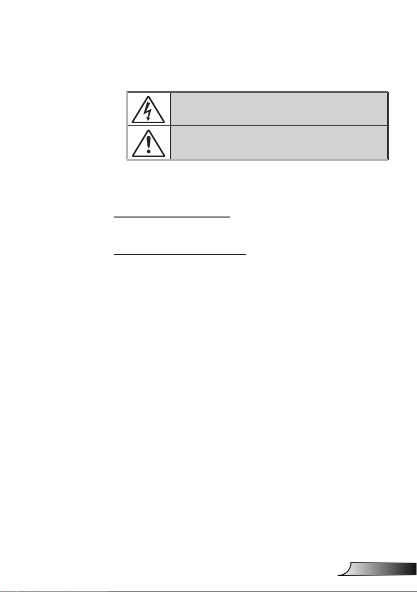
Package Overview
Unpack and inspect the box contents to ensure all parts
listed below are in the box. If something is missing,
please contact your nearest customer service center.
Standard Accessories
Optional accesso-
ries vary depending on model,
specication and
region.
For other laser
curtain accessories, please refer
to the laser curtain user manual.
*For European
warranty informa-
tion please visit
www.optomaeu-
rope.com
Projector
Warranty Card*
Basic User
Manual
2 AAA Batteries
Documentation
Optional Accesories
VGA Cable
Power Cord
HDMI Cable
Remote
Laser Curtain Module
Wi Dongle
Page 7
7
English
Introduction
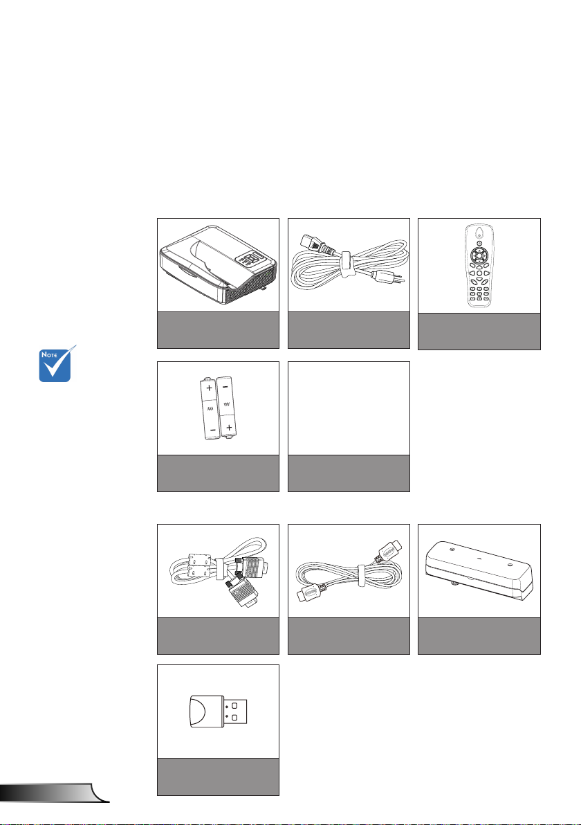
Product Overview
Main Unit
5
1
2
The interface
is subject to
model’s
specications.
Do not block pro-
jector in/out air
vents and keep
a minimum 30cm
distance.
4
9
8
7
1. Control Panel
2. Focus Switch
3. Ventilation (inlet)
4. IR Receiver
5. Ventilation (outlet)
3
6
6. Speaker
7. Power Socket
8. Input / Output
Connections
9. Lens
Page 8
8
English
Introduction
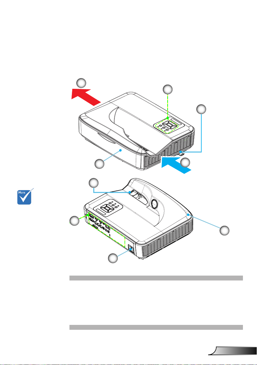
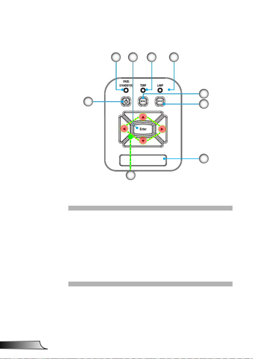
Control Panel
21 4
8
7
1. Power LED
2. Enter
3. Temp LED
4. Lamp LED
5. Menu
6. Input
7. Four Directional Select Keys
8. Power/Standby button
9. IR Receiver
3
5
6
9
Page 9
9
English
Introduction
The interface
7
1 2
4
10
14
53
11
12
16
6
9
13 15
17
8
is subject to
model’s
specications.
Monitor loop
through only
support in VGA1In/YPbPr.
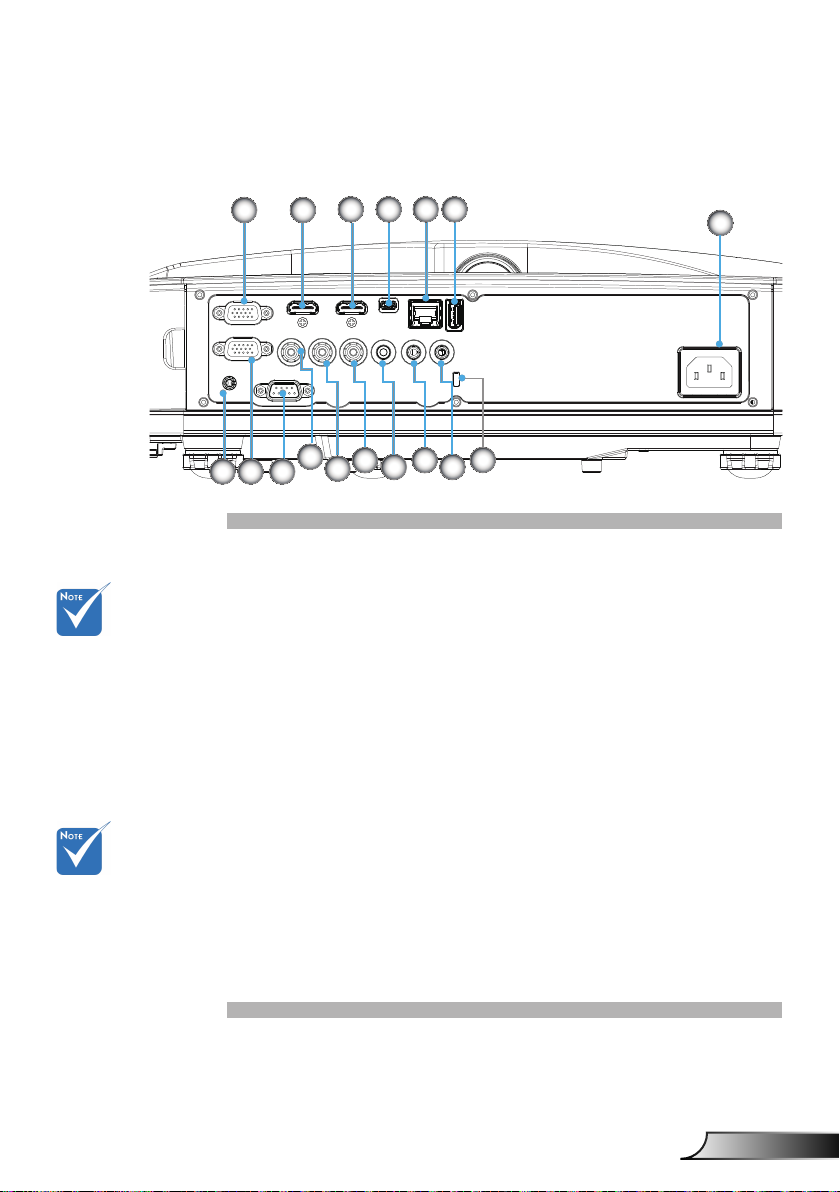
Input/Output Connections
VGA1-In/YPbPr Connector 1.
(PC Analog Signal/Component Video Input/HDTV/YPbPr)
HDMI2 Input Connector 2.
HDMI1 Input Connector 3.
USB Connector (Connect to PC for Remote Mouse 4.
function)
RJ45 connector5.
USB Type A Connector6.
Power Socket7.
Interactive connector (3.5mm mini-jack, depending on 8.
Model)
VGA-Out/VGA2-In Connector9.
RS-232 Connector (9-pin DIN Type)10.
Composite Video Input Connector11.
Composite Audio Input (right) Connector 12.
Composite Audio Input (left) Connector 13.
Audio Output Connector (3.5mm mini jack) 14.
Audio Input Connector (3.5mm mini jack) 15.
Audio Input Connector (microphone) 16.
Kensington17.
TM
Lock Port
Page 10
10
English
Introduction
HDMI2
HDMI1
VGA1
VGA2
Freeze
Blank
Image
Aspect
Keystone
Volume
Zoom-
Reset
Auto
Input
Zoom+
M
Power
enu
Exit
Enter
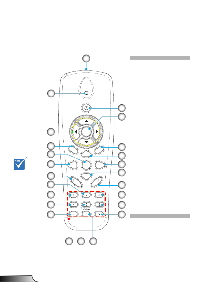
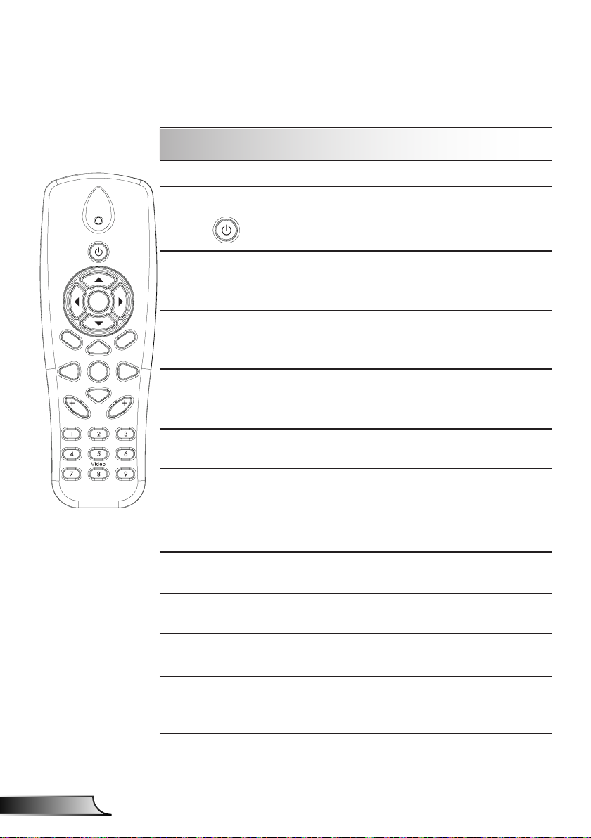
Remote Control
2
5
6
Some keys
may have
not function
for models
which do not
support these
features.
9
10
14
15
16
18
20
1
Infrared transmitter1.
LED Indicator2.
Power On/Off3.
OK4.
Four Directional Select 5.
Keys
Menu6.
3
4
Exit7.
Zoom in8.
Reset9.
Auto10.
Source11.
Zoom out12.
Volume +/-13.
7
Keystone +/-14.
Image15.
8
11
12
Black screen16.
Aspect ratio17.
VGA118.
HDMI119.
VGA220.
13
17
19
HDMI2 21.
Video22.
Screen freeze23.
Numbered keypad 24.
(for password input)
21
24
2223
Page 11
11
English
Installation
E62405SP
R
1
MOLEX
10
9
5
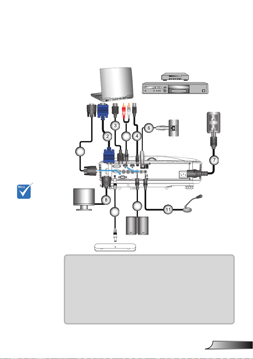
Connecting the Projector
Connect to Computer/Notebook
Router / Network Switch
DVD Player, Set-top Box,
HDTV receiver
Due to the
(*) Optional
difference in
applications for
each country,
some regions may
have different
accessories.
accessory
Microphone
External
Display
Audio Output
1................................................................................................*RS232 Cable
2................................................................................................... *VGA Cable
3..................................................................................................*HDMI Cable
4....................................................................................................*USB Cable
5......................................................................................... *Audio Cable/RCA
6.................................................................................................. *RJ45 Cable
7....................................................................................................Power Cord
8........................................................................................*VGA Output Cable
9............................................................................................Interactive Cable
10....................................................................................*Audio Output Cable
11 ............................................................................. *Microphone Input Cable
Page 12
12
English
Installation
E62405SP
R
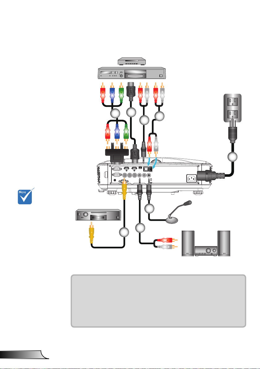
Connect to Video Sources
DVD Player, Set-top Box,
HDTV receiver
2
1
3
4
5
Due to the
difference in
applications for
each country,
some regions may
have different
accessories.
(*) Optional
accessory
Composite Video Output
6
1................................................*15-Pin to 3 RCA Component/HDTV Adaptor
2..................................................................................................*HDMI Cable
3..................................................................................................*Audio Cable
4......................................................................................... *Audio Cable/RCA
5....................................................................................................Power Cord
6................................................................................*Composite Video Cable
7......................................................................................... *Audio Cable/RCA
8.........................................................................................*Audio Input Cable
8
Microphone
7
Audio Output
Page 13
13
English
Installation
Powering the Projector On / Off
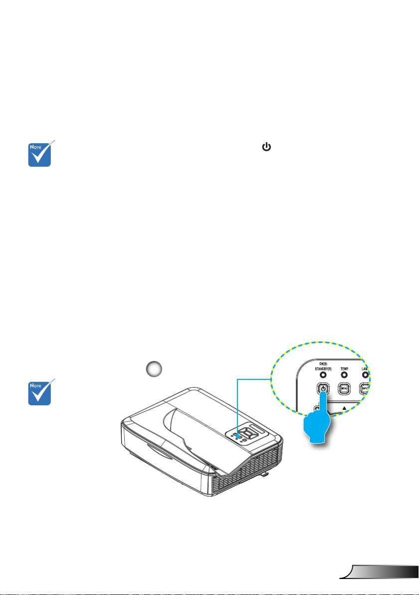
Powering On the Projector
1. Securely connect the power cord and signal cable. When
connected, the POWER/STANDBY LED will turn Orange.
When the power
mode is in standby
mode (power consumption < 0.5W),
the VGA output/
input and audio
will be deactivated
when the projector
is in standby.
Turn on the
projector rst and
then select the
signal sources.
2. Turn on the lamp by pressing “
” button either on the
projector or on the remote. At this moment, the POWER/
STANDBY LED will now turn Blue.
The startup screen will display in approximately 10 sec-
onds. The rst time you use the projector, you will be asked
to select the preferred language and power saving mode.
3. Turn on and connect the source that you want to display
on the screen (computer, notebook, video player, etc). The
projector will detect the source automatically. If not, push
menu button and go to “OPTIONS”.
Make sure that the “Source Lock” has been set to “Off”.
If you connect multiple sources at the same time, press the
“INPUT” button on the control panel or direct source keys
on the remote control to switch between inputs.
1
POWER/STANDBY
Page 14
14
English
Installation
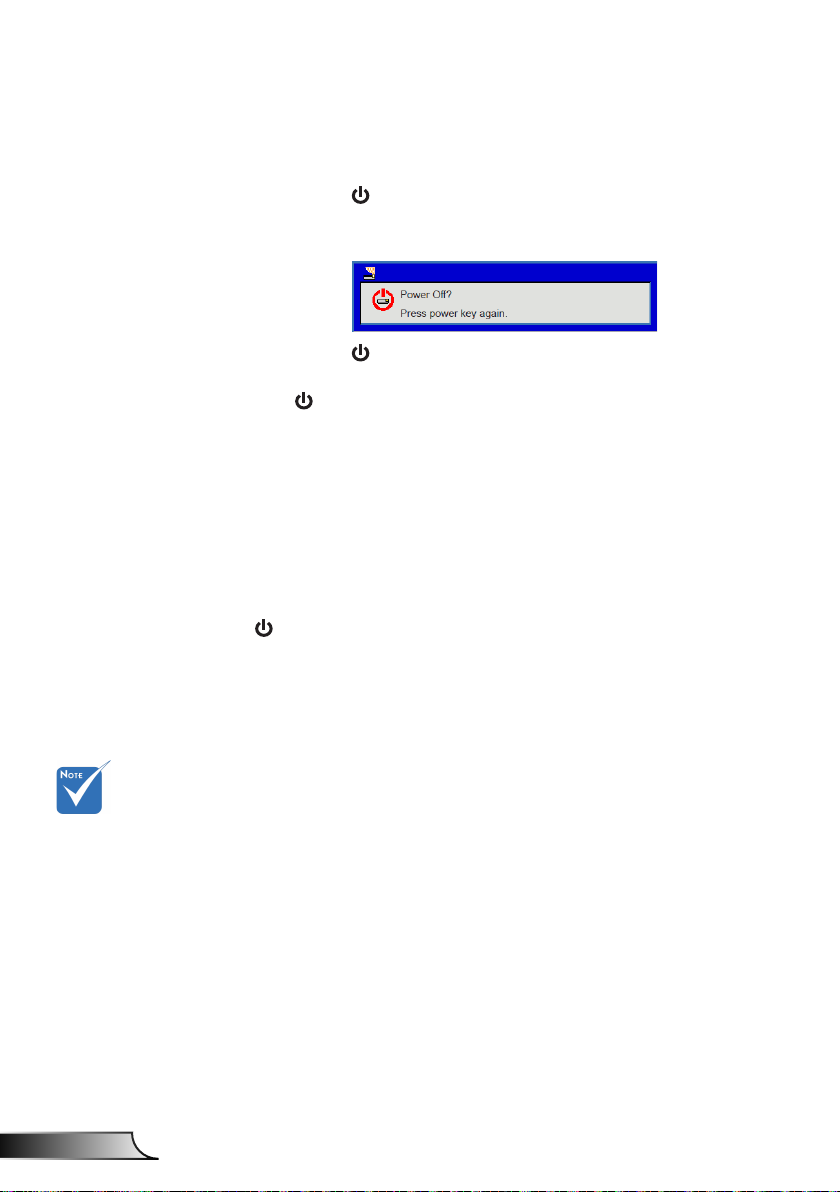
Powering Off the Projector
1. Press the “ ” button on the remote control or
on the control panel to turn off the projector.
The following message will be displayed on the screen.
Press the “ ” button again to conrm otherwise the
message will disappear after 10 seconds. When you press
the “ ” button for the second time, the fan will start cooling
the system and will shut down.
2. The cooling fans continue to operate for about 4 seconds
for cooling cycle and the POWER/STANDBY LED will ash
Orange. When the POWER/STANDBY LED lights solid
Orange, the projector has entered standby mode.
If you wish to turn the projector back on, you must wait until
the projector has completed the cooling cycle and has entered standby mode. Once in standby mode, simply press “
3. Disconnect the power cord from the electrical outlet and the
projector.
” button to restart the projector.
Contact the
nearest service
center if the
projector displays
these symptoms.
Warning Indicator
When the warning indicators (see below) come on,
the projector will automatically shutdown:
“LAMP” LED indicator is lit red and if “POWER/STANDBY”
indicator ashes amber.
“TEMP” LED indicator is lit red, this indicates the projector
has overheated. Under normal conditions, the projector can
be switched back on.
“TEMP” LED indicator ashes red and if “POWER/STAND-
BY” indicator ashes amber.
Unplug the power cord from the projector, wait for 30 seconds
and try again. If the warning indicator light up again, please
contact your nearest service center for assistance.
Page 15
15
English
Installation
Adjusting the Projected Image
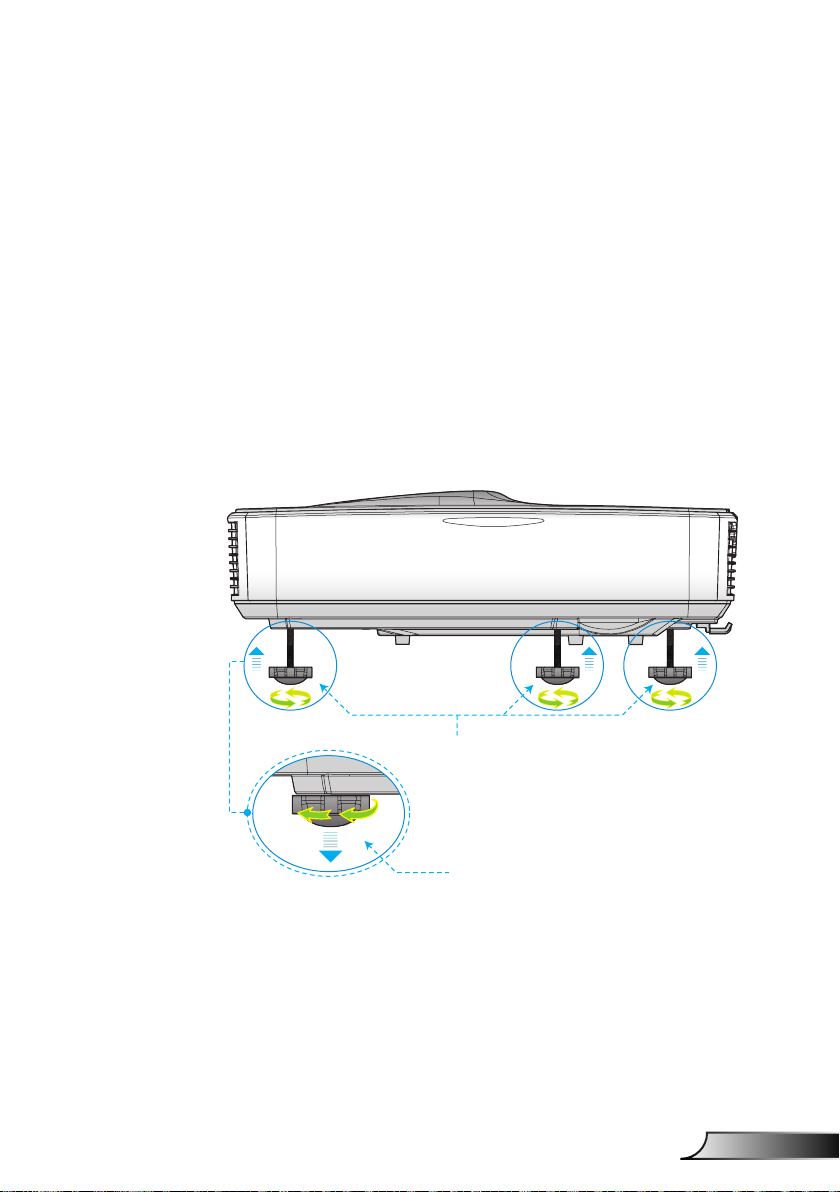
Adjusting the Projector�s Height
The projector is equipped with elevator feet for adjusting
the image height.
1. Locate the adjustable foot you wish to modify on the
underside of the projector.
2. Rotate the adjustable ring clockwise to raise the projector
or counter clockwise to lower it. Repeat with the remain-
ing feet as needed.
Tilt-Adjustment Feet
Tilt-Adjustment Ring
Page 16
16
English
Installation
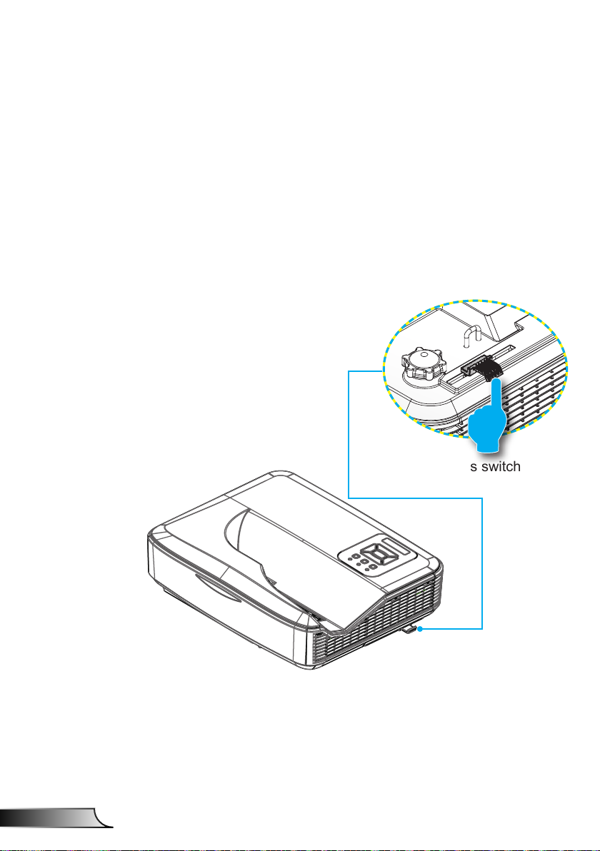
Adjusting the Projector�s Focus
To focus the image, slide the focus switch to left/right until the
image is clear.
1080p series: The projector will focus at distances from
1.443 to 1.887 feet (0.437 to 0.572 meters).
WXGA series: The projector will focus at distances (lens to
wall) from 1.59~2.16 feet (0.49~0.66 meters)
Focus switch
Page 17
17
English
Installation
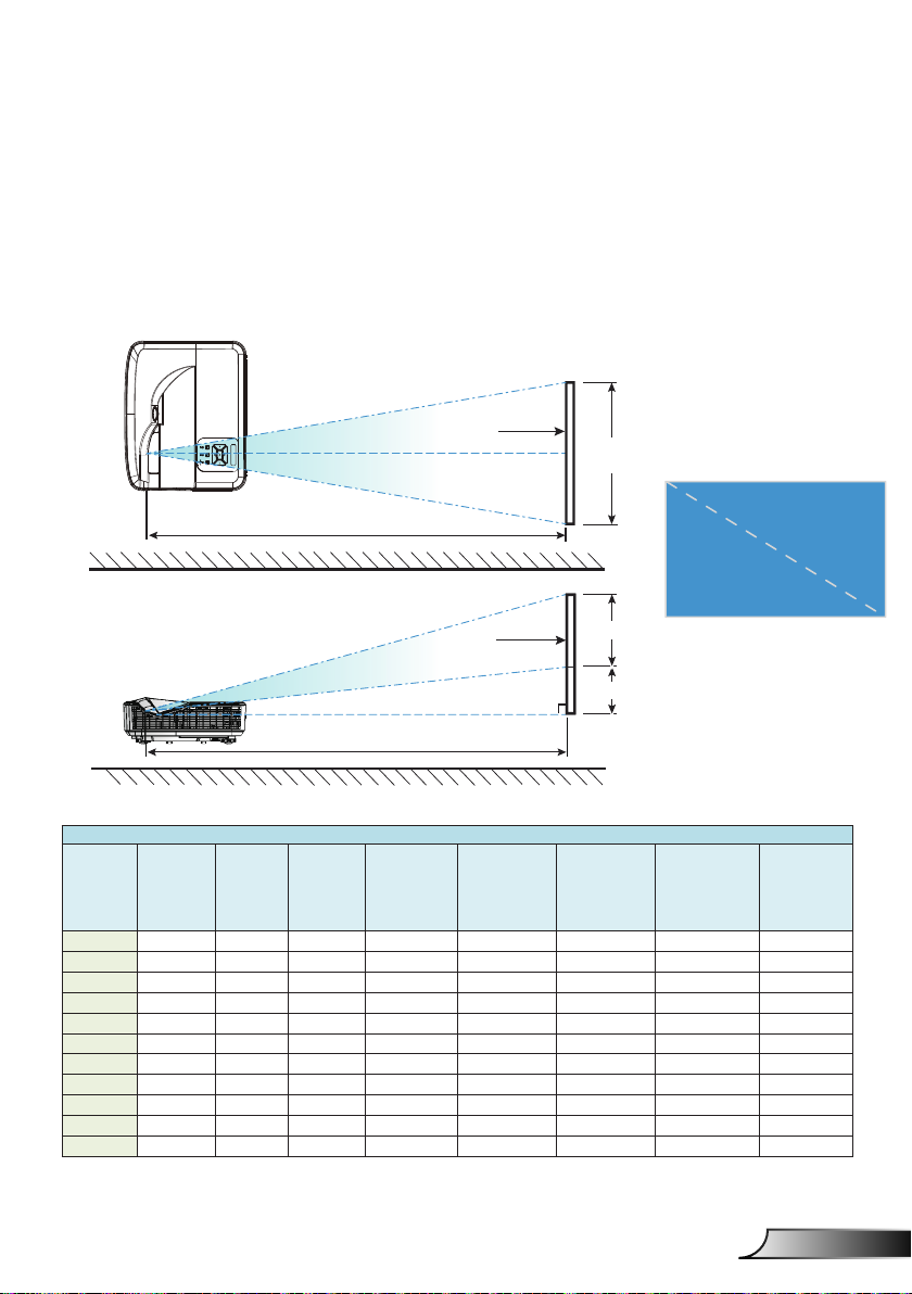
Top View
Adjusting Projection Image Size (Diagonal)
1080p series: Projection Image Size from 80” to 100” (2.03
to 2.54 meters).
WXGA series: The projector will focus at distances (lens to
wall) from 1.59~2.16 feet (0.49~0.66 meters)
Screen
Screen (W)
Projection Distance (D)
Height
Screen
Side View
Projection Distance (D)
1080P (16:9) Wall mount installaon measurement chart
Diagonal
image size (S)
in inch
Diagonal
in mm
Image width
(W) in mm
image size (S)
87 2210 1926 1083 370 233 364 288 268
88 2235 1948 1096 376 239 367 291 271
89 2261 1970 1108 382 245 370 294 274
90 2286 1992 1121 387 250 372 296 276
91 2311 2015 1133 393 256 375 299 279
92 2337 2037 1146 398 261 377 301 281
93 2362 2059 1158 404 267 380 304 284
94 2388 2081 1171 409 272 383 307 287
95 2413 2103 1183 415 278 385 309 289
96 2438 2125 1196 421 284 388 312 292
97 2464 2147 1208 426 289 390 314 294
Image height
(H) in mm
Distance from
surface of
whiteboard
to center of
projector mount
(T) in mm
Distance from
surface of
whiteboard to
back of projector
(T1) in mm
Screen (H)
Offset (Hd)
Distance from
top of image to
top of wall plate
(O) in mm
Distance from top
of image to top of
interface boss (O1)
in mm
Diagonal
Width
Distance from
top of image to
top of projector
(O2) in mm
Page 18
18
English
Installation
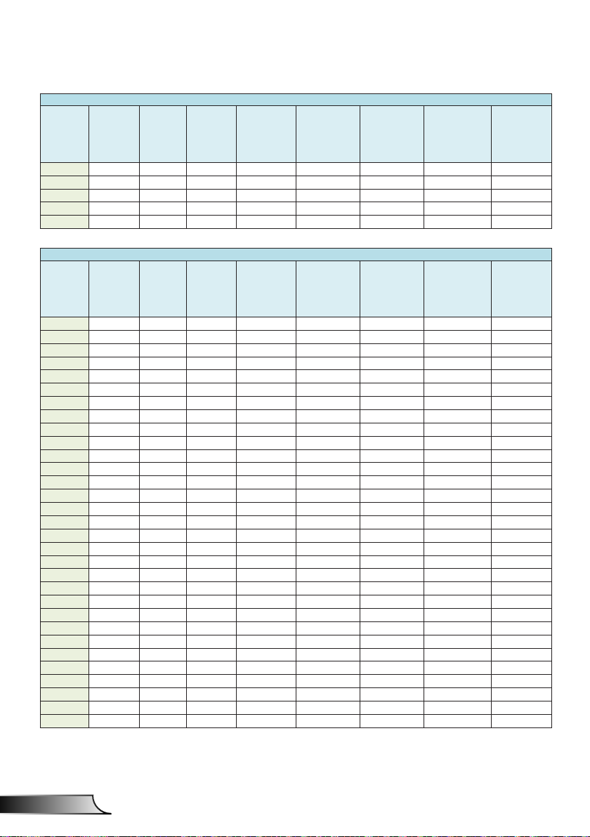
1080P (16:9) Wall mount installaon measurement chart
Diagonal
image size (S)
in inch
Diagonal
in mm
Image width
(W) in mm
image size (S)
98 2489 2170 1220 432 295 393 317 297
99 2515 2192 1233 437 300 396 320 300
100 2540 2214 1245 443 306 398 322 302
101 2565 2236 1258 448 311 401 325 305
102 2591 2258 1270 454 317 403 327 307
Image height
(H) in mm
WXGA (16:10) Wall mount installaon measurement chart
Diagonal
image size (S)
in inch
Diagonal
in mm
Image width
(W) in mm
image size (S)
85 2159 1831 1144 370 233 342 266 246
86 2184 1852 1158 376 239 344 268 248
87 2210 1874 1171 382 245 346 270 250
88 2235 1895 1185 387 250 349 273 253
89 2261 1917 1198 393 256 351 275 255
90 2286 1939 1212 399 262 353 277 257
91 2311 1960 1225 404 267 356 280 260
92 2337 1982 1239 410 273 358 282 262
93 2362 2003 1252 416 279 361 285 265
94 2388 2025 1265 422 285 363 287 267
95 2413 2046 1279 427 290 365 289 269
96 2438 2068 1292 433 296 368 292 272
97 2464 2089 1306 439 302 370 294 274
98 2489 2111 1319 444 307 373 297 277
99 2515 2132 1333 450 313 375 299 279
100 2540 2154 1346 456 319 377 301 281
101 2565 2175 1360 461 324 380 304 284
102 2591 2197 1373 467 330 382 306 286
103 2616 2219 1387 473 336 384 308 288
104 2642 2240 1400 479 342 387 311 291
105 2667 2262 1414 484 347 389 313 293
106 2692 2283 1427 490 353 392 316 296
107 2718 2305 1440 496 359 394 318 298
108 2743 2326 1454 501 364 396 320 300
109 2769 2348 1467 507 370 399 323 303
110 2794 2369 1481 513 376 401 325 305
111 2819 2391 1494 519 382 403 327 307
112 2845 2412 1508 524 387 406 330 310
113 2870 2434 1521 530 393 408 332 312
114 2896 2455 1535 536 399 411 335 315
115 2921 2477 1548 541 404 413 337 317
Image height
(H) in mm
Distance from
surface of
whiteboard
to center of
projector mount
(T) in mm
Distance from
surface of
whiteboard
to center of
projector mount
(T) in mm
Distance from
surface of
whiteboard to
back of projector
(T1) in mm
Distance from
surface of
whiteboard to
back of projector
(T1) in mm
Distance from
top of image to
top of wall plate
(O) in mm
Distance from
top of image to
top of wall plate
(O) in mm
Distance from top
of image to top of
interface boss (O1)
in mm
Distance from top
of image to top of
interface boss (O1)
in mm
Distance from
top of image to
top of projector
(O2) in mm
Distance from
top of image to
top of projector
(O2) in mm
This table is for user’s reference only.
Page 19
19
English
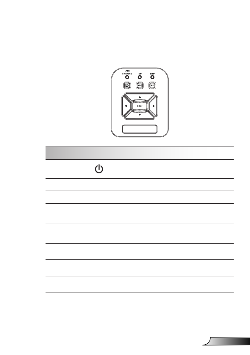
Control Panel & Remote Control
Control Panel
Using the Control Panel
User Controls
POWER
Enter Press “Enter” to conrm your item selection.
INPUT Press “INPUT” to select an input signal.
MENU
Four Directional
Select Keys
LAMP LED
TEMP LED
ON/STANDBY
LED
Refer to the “Power On/Off the Projector”
section on pages 13-14.
Press “MENU” to launch the on-screen display
(OSD) menu. To exit OSD, press “MENU” again.
Use ▲▼◄► to select items or make
adjustments to your selection.
Refer to the LED indicator of the projector light
source status.
Refer to the LED indicator of the projector
temperature status.
Refer to the LED indicator of the projector
power status.
Page 20
20
English
User Controls
HDMI2
HDMI1
VGA1
VGA2
Freeze
Blank
Image
Aspect
Keystone
Volume
Zoom-
Reset
Auto
Input
Zoom+
M
Power
enu
Exit
Enter
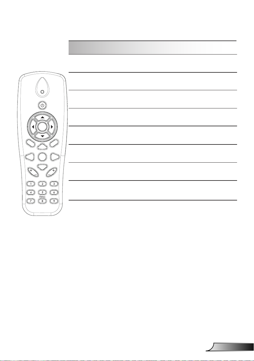
Remote Control
Using the Remote Control
Infrared transmitter Sends signals to the projector.
LED LED Indicator.
Power
Refer to the “Power On/Off the
Projector” section on pages 15-16.
Exit Press “Exit” to close the OSD menu.
Zoom in Zoom in the projector display.
Return the adjustments and settings to
Reset
the factory default values. (except for
lamp counter)
Zoom out Zoom out the projector display.
Enter Conrm your item selection.
Source
Auto
Four Directional
Select Keys
Keystone +/-
Volume +/-
Aspect ratio
Press “Source” to select an input
signal.
Automatically synchronizes the
projector to the input source.
Use ▲▼◄► to select items or make
adjustments to your selection.
Adjust image distortion caused by tilting
the projector.
Adjust to increase / decrease the
volume.
Use this function to choose your desired aspect ratio.
Press “Menu” to launch the on-screen
Menu
display (OSD) menu. To exit OSD,
press “Menu” again.
Page 21
21
English
User Controls
Using the Remote Control
HDMI2
HDMI1
VGA1
VGA2
Freeze
Blank
Image
Aspect
Keystone
Volume
Zoom-
Reset
Auto
Input
Zoom+
M
Power
enu
Exit
Enter
VGA1
Blank screen
HDMI1
HDMI2
VGA2
Video
Screen freeze
Image
Press “VGA1” to choose VGA IN 1
connector.
Momentarily turns off/on the audio and
video.
Press “HDMI1” to choose HDMI IN 1
connector.
Press “HDMI2” to choose HDMI IN 2
connector.
Press “VGA2” to choose VGA IN 2
connector.
Press “Video” to choose Composite
video source.
Pause the screen image. Press again
to resume the screen image.
Select the display mode from Bright,
PC, Movie, Game, and User.
Page 22

22
English
User Controls
IR Remote codes
key
legend
Power FF FF E8 17
Up FF FF E7 18
Left FF FF E6 19
Enter FF FF F8 7
4 FF FF F7 8
Down FF FF F6 9
Menu FF FF EB 14
Zoom+ FF FF FB 4
Exit FF FF FF 0
Auto FF FF FA 5
Reset FF FF EA 15
Input FF FF E0 1F
Zoom- FF FF FE 1
Keystone+ FF FF F0 0F
Keystone - FF FF E2 1D
Volume- FF FF F2 0D
Volume+ FF FF BD 42
Blank/1 FF FF BE 41
Image/2 FF FF F3 0C
Aspect3 FF FF E3 1C
VGA1 /4 FF FF BF 40
Freeze/5 FF FF EC 13
HDMI1/6 FF FF E5 1A
VGA2 /7 FF FF E4 1B
HDMI2 /8 FF FF EF 10
S-Video /9 FF FF E1 1E
Custom Code Data
Byte1 Byte2 Byte3 Byte4
NEC_CODE
Page 23
23
English
User Controls
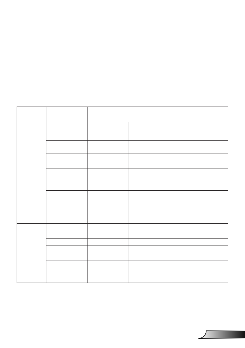
On-screen Display Menus
The Projector has multilingual On-screen Display menus that
allow you to make image adjustments and change a variety of
settings.
Structure
Note: Please note that the on-screen display (OSD) menus vary according to the signal
type selected and the pro jector model you are using.
Main Menu Sub Menu Setting
Picture
Screen
Color Mode
Wall Color
Brightness
Contrast
Sharpness
Saturation
Hue
Gamma
Color Temp
Color Matching
Aspect Ratio Auto/4:3/16:9/16:10
Phase
Clock
H.Position
V.Position
Digtial Zoom
Orientation Front/Front Ceiling/Rear/Rear Ceiling
Size
White/Red/
Green/Blue/Cyan/
Magenta/Yellow
Bright/PC/Movie/Game/Blending./User
(Change Color Mode to User Mode if
customer changes the settings)
White/ Light Yellow/ Light Blue/ Pink/ Dark
Green
Hue/ Saturation /Gain
Page 24
24
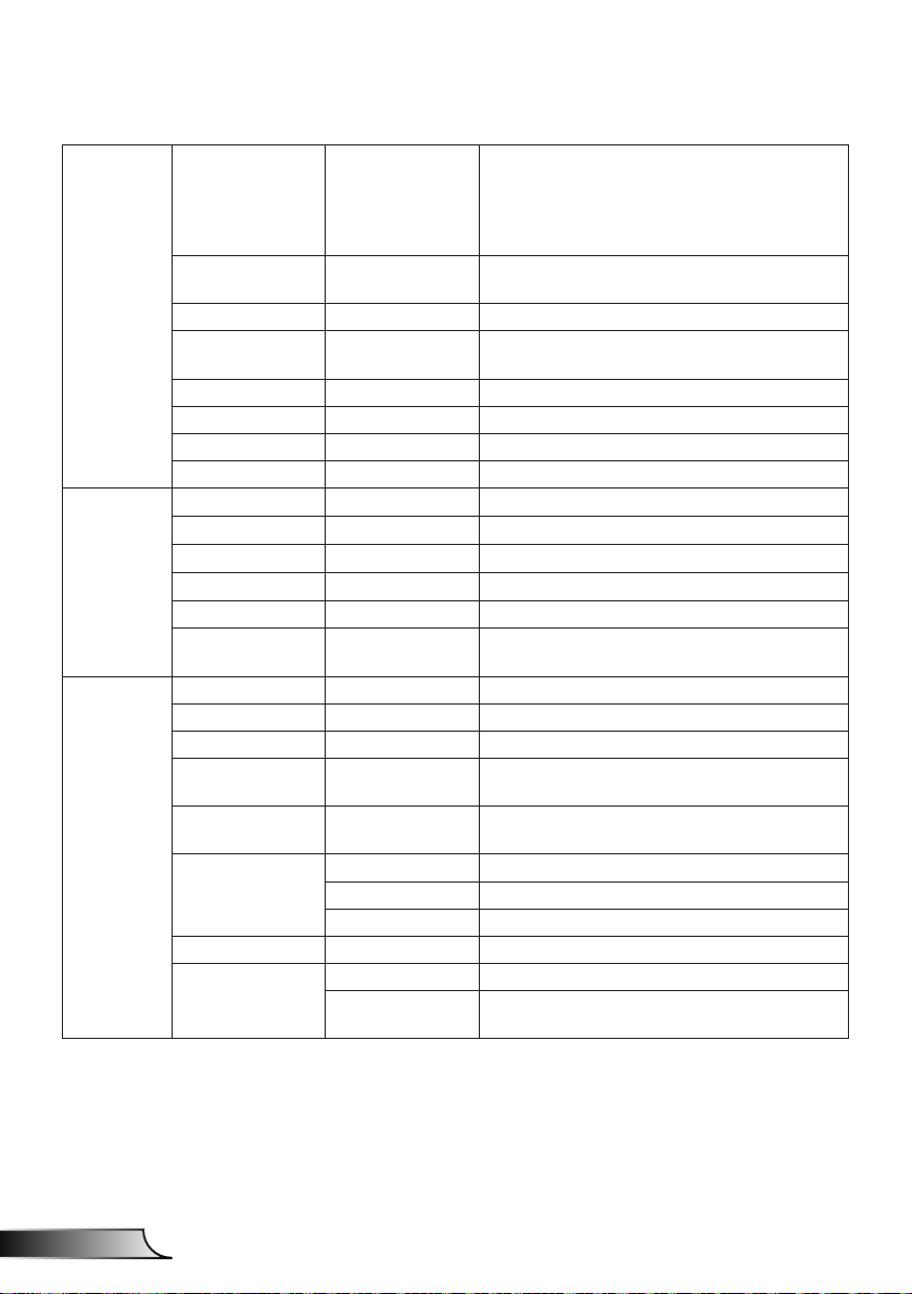
English
User Controls
Language
English/German/French/Italian/Spanish/
Polish/Swedish/Dutch/Portugese/Japanese/
Traditional Chinese/ Simplied Chinese/
Korean/Russian/Arabic/Norsk/Turkish/Danish
Settings
Volume
Options
Menu Location
Closed Caption Off/CC1/CC2/CC3/CC4
VGA OUT
(Standby)
LAN (Standby) Off/On
VGA-2 (Function) Inout/Output
Test Pattern Off/On
Reset to Default Yes/No
Speaker On/Off
Line Out On/Off
Microphone On/Off
Mute On/Off
Volume
Microphone
Volume
Logo Default/User
Logo Capture
Auto Source On/Off
Input
Auto Power Off
(Min.)
SSI Settings
SSI Power Mode Normal,ECO
High Altitude On/Off
Filter Reminder
Filter Settings
Cleaning Up
Reminder
Left Top, Right Top, Center, Left Bottom, Right
Bottom
Off/On
VGA-1,VGA-2, HDMI-1, HDMI-2,Video,
MULTIMEDIA
SSI Hours Used (Normal)
SSI Hours Used (ECO)
Yes/No
Page 25

25
English
User Controls
Model Name
SNID
Options Information
3D Off/On
3D Invert On/Off
3D
Interactive Interactive Setting On/Off(interactive SKU only)
Network
3D Format
1080p @ 24 96Hz/144Hz
Status
DHCP Client On/Off
IP Address
Subnet Mask
Gateway
DNS
MAC Address
Group Name
Projector Name
Location
Contact
Source
Resolution
SW Version
Aspect Ratio
Frame Packing
Side-by-Side (Half)
Top amd Bottom
Frame Sequential
Field Sequential
Page 26

26
English
User Controls
How to operate
1. To open the OSD menu, press “Menu” on the Remote Control or
Projector Keypad.
2 When OSD is displayed, use the
the main menu. While making a selection on a particular page,
press the ► or “Enter” key to enter sub menu.
3. Use the ▲▼ keys to select the desired item and adjust the
settings using the ◄► key.
4. Select the next item to be adjusted in the sub menu and adjust as
described above.
5. Press “Enter” to conrm, and the screen will return to the main
menu.
6. To exit, press “Menu” again. The OSD menu will close and the
projector will automatically save the new settings.
Main Menu
keys to select any item in
▲▼
SettingsSub Menu
Page 27

27
English
User Controls
Picture
Color Mode
There are many factory presets optimized for various types of im-
ages. Use the ◄ or ► button to select the item.
Bright: For brightness optimization.
PC: For meeting presentation.
Movie: For playing video content.
Game: For game content.
User: Memorize user’s settings.
Blending: For Blending application.
Wall Color
Use this function to obtain an optimized screen image according
to the wall color. You can select from “White”, “Light Yellow”, “Light
Blue”, “Pink”, and “Dark Green”.
Brightness
Adjust the brightness of the image.
Press the ◄ button to darken image.
Press the ► button to brighten image.
Contrast
The Contrast controls the difference between the lightest and darkest parts of the picture. Adjusting the contrast changes the amount
of black and white in the image.
Press the ◄ button to decrease the contrast.
Press the ► button to increase the contrast.
Page 28

28
English
User Controls
Sharpness
Adjust the sharpness of the image.
“Sharpness”, “Sat-
uration” and “Hue”
functions are only
supported under
video mode.
Press the ◄ button to decrease the sharpness.
Press the ► button to increase the sharpness.
Saturation
Adjust a video image from black and white to fully saturated color.
Press the ◄ button to decrease the amount of saturation in the
image.
Press the ► button to increase the amount of saturation in the
image.
Hue
Adjust the color balance of red and green.
Press the ◄ button to increase the amount of green in the im-
age.
Press the ► button to increase the amount of red in the image.
Gamma
This allows you to adjust the gamma value to obtain the better image contrast for the input.
Color Temp
This allows you to adjust the color temperature. At higher temperature, the screen looks colder; at lower temperature, the screen
looks warmer.
Color Settings
Use these settings for advanced adjustment of the individual
Red,Green,Blue,Cyan,Magenta and Yellow Colors.
Page 29

29
English
User Controls
Screen
Aspect Ratio
Auto: Keep the image with original width-height ratio and maxi-
mize the image to t native horizontal or vertical pixels.
4:3: The image will be scaled to t the screen and displayed
using a 4:3 ratio.
16:9: The image will be scaled to t the width of the screen and
the height adjusted to display the image using a 16:9 ratio.
16:10: The image will be scaled to t the width of the screen
and the height adjusted to display the image using a 16:10 ratio.
“H. Position” and
“V. Position” rang-
es will depend on
input source.
Phase
Synchronize the signal timing of the display with the graphic card.
If the image appears to be unstable or ickers, use this function to
correct it.
Clock
Adjust to achieve an optimal image when there is a vertical icker
in the image.
H. Position
Press the ◄ button to move the image left.
Press the ► button to move the image right.
Page 30

30
English
User Controls
V. Position
Press the ◄ button to move the image down.
Press the ► button to move the image up.
Digital Zoom
Press the ◄ button to reduce the size of an image.
Press the ► button to magnify an image on the projection
screen.
V Keystone
Press the ◄ or ► button to adjust image distortion vertically. If
the image looks trapezoidal, this option can help make the image
rectangular.
Orientation
Front: The image is projected straight on the screen.
Front Ceiling: This is the default selection. When selected, the
image will turn upside down.
Rear: When selected, the image will appear reversed.
Rear Ceiling: When selected, the image will appear reversed in
upside down position.
Page 31

31
English
User Controls
Setting
Language
Choose the multilingual OSD menu. Press the ◄ or ► button
into the sub menu and then use the ▲ or ▼ button to select your
preferred language. Press ► on the remote control to nalize the
selection.
Menu Location
Choose the menu location on the display screen.
Closed Caption
Use this function to enable close caption menu. Select an appropri-
ate closed captions option: Off, CC1, CC2, CC3, and CC4.
VGA Output (Standby)
Choose “On” to enable VGA OUT connection.
Page 32

32
English
User Controls
LAN (Standby)
Choose “On” to enable LAN connection. Choose “Off” to disable
LAN connection.
VGA B (Function)
Input: Choose “Input” to let the VGA port works as a VGA input
function.
Output: Choose “Output” to enable the VGA Out function once
the projector is powered on.
Test Pattern
Display a test pattern.
Reset
Choose “Yes” to return the parameters on all menus to the factory
default settings.
Page 33

33
English
User Controls
Volume
Speaker
Choose “On” to enable the speaker.
Choose “Off” to disable the speaker.
Line Out
Choose “On” to enable the line out function.
Choose “Off” to disable the line out function.
Microphone
Choose “On” to enable the microphone.
Choose “Off” to disable the microphone.
Mute
Choose “On” to turn mute on.
Choose “Off” to turn mute off.
Volume
Press the ◄ button to decrease the volume.
Press the ► button to increase the volume.
Microphone Volume
Press the ◄ button to decrease the microphone volume.
Press the ► button to increase the microphone volume.
Page 34

34
English
User Controls
Options
Logo
Use this function to set the desired startup screen. If changes are
made they will take effect the next time the projector is powered
on.
Default: The default startup screen.
User: Use stored picture from “Logo Capture” function.
For successful logo
capture, please
ensure that the
on-screen image
does not exceed
the projector’s
native resolution.
(WXGA:1280x800).
“Logo Capture” is
not available when
3D is enabled.
Before active
this function, it is
recommended that
“Aspect Ratio” is
set to the “Auto”.
When auto source
is ON the sys-
tem will search
Multimedia source
if user had ever
chosen multimedia
source or it will skip
multimedia source.
Logo Capture
Press ► button to capture an image of the picture currently displayed on screen.
Auto Source
On: The projector will search for other signals if the current input
signal is lost.
Off: The projector will only search current input connection.
Input
Press ► button to enable/disable input sources. The projector will
not search for inputs that are not selected.
Page 35

35
English
User Controls
Dynamic Black”
is available when
“Color Mode” is
set to “Movie”.
When “Dynamic
Black” is available, “Laser
Power Mode”
selection is not
available.
Auto Power Off (Min)
Sets the countdown timer interval. The countdown timer will start,
when there is no signal being sent to the projector. The projector
will automatically power off when the countdown has nished (in
minutes).
Laser Settings
Refer to page 32.
High Altitude
On: The built-in fans run at high speed. Select this option when
using the projector at altitudes above 2500 feet/762 meters or
higher.
Off: The built-in fans automatically run at a variable speed ac-
cording to the internal temperature.
Filters Remind (Hour)
Filters Remind (Hour): Set the lter reminder time.
Cleaning Up Remind: Select “Yes” to reset the dust lter hour
counter after replacing or cleaning the dust lter.
Information
Display the projector information for model name, SNID, source,
resolution, software version, and aspect ratio on the screen.
Page 36

36
English
User Controls
Options |
Laser Settings
Laser Hours Used (Normal)
Display the projection time of normal mode.
Laser Hours Used (ECO)
Display the projection time of ECO mode.
Laser Power Mode
Normal: Normal mode.
ECO: Use this function to dim the projector lamp which will
lower power consumption and extend the lamp life.
Page 37

37
English
User Controls
3D
“Frame Sequen-
tial” is supported
the DLP Link 3D
input signals from
VGA / HDMI connector.
“Frame Sequen-
tial” / “Field Sequential” are supported the HQFS
3D input signals
from Composite/
S-Video connector
connector.
“Frame Pack-
ing” / “Side-bySide(Half)” / “Top
and Bottom” are
supported from
HDMI 1.4a 3D
input signals.
3D
Auto: When a HDMI 1.4a 3D timing identication signal is de-
tected, the 3D image is selected automatically.
Choose “On” to enable 3D function.
Choose “Auto” to detected 3D signal automatically.
3D Invert
If you see a discrete or overlapping image while wearing DLP 3D
glasses, you may need to execute “Invert” to get best match of left/
right image sequence to get the correct image.
3D Format
Use this feature to select the 3D format. Options are: “Frame
Packing”, “Side-by-Side (Half)”, “Top and Bottom”, “Frame Sequential”, and “Field Sequential”.
1080p@24
Use this feature to select 96 or 144Hz refresh rate as using 3D
glasses in the1080p @ 24 frame packing.
Page 38

38
English
User Controls
Status
Display the network connection status.
IP, Subnet Mask,
Gateway, and
DNS congura-
tion assignment
please access to
web control page.
How to access
web control page
please refer to
page 36.
DHCP
Congure the DHCP settings.
On: Choose “On” to let the projector to obtain an IP address
automatically from your network.
Off: Choose “Off” to assign IP, Subnet Mask, Gateway, and DNS
configuration manually.
IP Address
Display an IP address.
LAN
Subnet Mask
Display the subnet mask number.
Page 39

39
English
User Controls
Gateway
Display the default gateway of the network connected to the pro-
jector.
DNS
Display the DNS number.
MAC Address
Display the MAC address.
Group Name
Display the group name.
Projector Name
Display the projector name.
Location
Display the projector location.
Contact
Display the contact information.
Page 40

40
English
User Controls
How to use web browser to control your projector
1. Turn on DHCP to allow a DHCP
server to automatically assign an IP, or
manually enter the required network
information.
2. Then choose apply and press
button to complete the conguration
process.
3. Open your web browser and type in IP
Address from the OSD LAN screen then
the web page will display as below:
4. Based on network web-page for the
input-string in [tools] tab, the limitation
for Input-Length is in the below list
(“space” and the other punctuation key
included):
Category Item
IP Address 15
Crestron Control
Projector
Network
Conguration
User Password
Admin Password
IP ID 2
Port 5
Projector Name 10
Location 9
Assigned To 9
DHCP (Enabled) (N/A)
IP Address 15
Subnet Mask 15
Default Gateway 15
DNS Server 15
Enabled (N/A)
New Password 15
Conrm 15
Enabled (N/A)
New Password 15
Conrm 15
Input-Length
(characters)
When you used the projector IP
address, you will can not link to your
service server.
Page 41

41
English
User Controls
When making a direct connection from your computer to the projector
Step 1: Find an IP Address (192.168.0.100) from LAN function of projector.
Step 2: Select apply and press “Enter” button to submit function or press “menu” key to
exit.
Step 3: To open Network Connections,
click Start, click Control Panel,
click Network and Internet
Connections, and then click
Network Connections. Click the
connection you want to congure,
and then, under Network Tasks
, click Change settings of this
connection.
Step 4: On the General tab, under
This connection uses the
following items, click Internet
Protocol (TCP/IP), and then click
“Properties.”
Step 6: To open Internet Options, click IE
web browser, click Internet Options,
click the Connections tab and click
“LAN Settings...”.
Step 7: The Local Area Network (LAN)
Setting dialog box appears. In the
Proxy Server area, cancel the
Use a proxy server for your LAN
check box, then click “OK” button
twice.
Step 5: Click Use the following IP
address, and type in as below:
1) IP address: 192.168.0.100
2) Subnet mask: 255.255.255.0
3) Default gateway:192.168.0.254
Step 8: Open your IE and type in the IP
address of 192.168.0.100 in the
URL then press “Enter” key.
Page 42

42
English
User Controls
Crestron RoomView Control Tool
Crestron RoomView™ provides a central monitoring station for 250+
control systems on a single Ethernet network (more are possible,
the number depends on the combination of IP ID and IP address).
Crestron RoomView monitors each projector, including projector’s
online status, system power, lamp life, network setting and hardware
faults, plus any custom attribute as dened by the Administrator.
The Administrator can add, delete, or edit room information, contact
information and events, which are logged automatically by the
software for all users. (Operation UI as following image)
1. Main Screen
Crestron Room-
View’s function is
set according to the
products’ models and
specications.
2. Edit Room
Page 43

43
English
User Controls
3. Edit Attribute
4. Edit Event
For further information, please visit:
http://www.crestron.com & www.crestron.com/getroomview.
Page 44

44
English
Multimedia
E62405SP
R
Accessing Multimedia Files
This projector supports two methods to project the media les
(photos, videos, music, documents) stored on following devices:
a. Via Wireless dongle (optional) - wirelessly access the media les
stored on your mobile phone, tablet PC, notebook, or desktop.
b. Via USB ash drive - directly access the media les stored in the
device.
How to access Multimedia mode
1. Plug a wireless dongle or a USB ash drive into the USB
connector at the back of projector.
In Multimedia
source mode the
keypad MENU key
is used as EXIT
key. User can press
keypad“Power”key
then press keypad
“MENU” key to show
MENU OSD in Multimedia source mode.
When Auto Source
is ON the system
will search Multimedia source if user
had ever chosen
Multimedia source or
it will skip Multimedia
source.
The projector will
automatically restart
the Multimedia
system and back to
Multimedia menu if
there is no any action
after few hours.
2. Press “INPUT” on the remote control or on the control panel to turn
on the projector. When the Input menu appears, press the
keys to select “Multimedia” and the “Enter” key to conrm.
▲▼
Page 45

45
English
Multimedia
Mobile Display
To access the media les stored on your mobile device or tablet
PC, do the folllowing:
1. On Multimedia menu, select Mobile/Tablet.
2. On your mobile device or tablet PC, download “EZ-View”
application App Store (iOS) or Play Store (Android).
3. Enable your mobile device or tablet PC WiFi function, and
search the AP name listed in the Wi-Fi network list.
4. The WIFI initial connection, you will be prompted to enter a
password. Enter the password as screen AP Name as step2.
5. Launch “EZ-View” application and enter the PCTOOL
password as step3
6. Wait until the connection is established. The media les on
your mobile device or tablet PC can be accessed using the
projector.
Page 46

46
English
Multimedia
Laptop Display
To access the media les stored on your laptop/notebook, do the
folllowing:
1. On Multimedia menu, select Laptop.
2. Enable your laptop/notebook WiFi function, and search the AP
name listed in the Wi-Fi network list.
3. On the WIFI initial connection, you will be prompted to enter a
password. Enter the password as step2.
4. Open your web browser and enter the IP address under the
same subnet. Then select “Wi” on the left side of web page to
install application required by the operation system.
5. After install completed. Launch “EZ-View” application and enter
the control code shown on the right-bottom side of the screen.
Page 47

47
English
Multimedia
6. Wait until the connection is established. The media les on your
laptop/notebook can be accessed using the projector.
Desktop Display
To access the media les stored on your desktop, do the
folllowing:
1. On Multimedia menu, select Desktop.
2. Open your web browser and enter the IP address. Then select
“Wi” on the left side of the screen and install application
required by the operation system.
Page 48

48
English
Multimedia
3. After install complete. Launch “EZ-View” application and enter
4. Wait until the connection is established. The media les on
EZ-View
1. Before opening the EZ-View application, user must input the
2. The application provides following function for image mirroring.
3. Mode selection: graphic mode provide slower reesh rate,
4. Display selection: can display desktop or extension desktop on
5. Split screen: can mirror different users on screen. Maximum
the control code shown on the right-bottom side of the screen.
your desktop can be accessed using the projector.
password displayed on screen.
better quality image. Video mode have better reesh
performance to display video.
your laptop or PC.
number of screen is four.
PowerPoint
animations are not
supported.
Details about MMA
support list please
refer to Appendices.
USB Storage Display
To access the media les stored on your USB ash drive, do the
folllowing:
Page 49

49
English
Multimedia
Supported File Format
Multimedia Category File Format
Photo BMP, JPG, PNG
Music MP3, WMA
Video AVI, MOV, MP4, RM, RMVB, DAT, MPG,
Document WORD, EXCEL, PPT*, PDF
1. On Multimedia menu, select USB Disk. Sometimes selecting
USB is slower. This is resulted from ready USB media.
ISO, TS, MKV, VOB, and WMV
2. Use the ▲▼ keys to select the le category and press the
“Enter” key.
Page 50

50
English
Multimedia
3. Use the ▲▼ keys to select the le to view/play and press the
Photo
1. Select the Photo will enter to le list.
2. Select one picture and push the enter key.
The tool bar includes whirling, full screen (keep the original
“Enter” key to conrm.
Use up, down, left, right key to select the picture.
Push enter key to show the tool bar, push back key to display
tool bar.
ratio), previous image next image, slide show, delete, image
information and exit.
User rst press “Enter” key to select one of function on tool
bar and then continue press the “Enter” to proceed different
options on the function. Then press left /right to previous/next
function. But when user selects rotation/zoom, user can press
the “Enter” key to toggle between different options. User can
press “Exit” key to leave the function.
Page 51

51
English
Multimedia
Functions Dened
Degree change: 0, 90, 180, 270
Enter key looping
Back key leave and no save function
Zoom in: x1, x2, x3, x4
Enter key looping
In zoom in mode use arrow key to move content.
Back key leave and no save function
Full screen
Keep image ratio and no save function
Previous image
Next image
Slide show
Press to start and re-press to stop
Delete from USB disk
Copy to internal memory
Not support in this model
Information
Close tool bar
Video
1. Select the Video will enter to le list
Use up and down key to select the video le.
Page 52

52
English
Multimedia
2. Select the video le and push the enter key to play video.
Functions Key dened
reverse left key
forward right key
play/ pause enter
display mode
Push enter key to show the tool bar, push back key to display
tool bar.
only show the play mode was repeat or single
To congure the play mode, user can reach to
settings/Video/repeat mode to change the repeat
mode
Music
1. Select the Music will enter to le list.
Use up and down key to select the audio le.
Page 53

53
English
Multimedia
2. Select the audio le and push enter key to play music.
Functions Key dened
previous le up key
next le down key
rewind left key
forward right key
play/ pause enter
only show the play mode was repeat or single
display mode
To congure the play mode, user can reach to
settings/Music/repeat mode to change the repeat
mode
Page 54

54
English
Multimedia
Ofce viewer
1. Select the ofce viewer will enter to le list.
2. Select one document and push the enter key.
Use up and down key to select the document le.
Push enter key to show the tool bar, push back key to display
tool bar.
The tool bar includes screen pan, zoom in, zoom out,
information.
Functions Dened
Left shift content
Enter key to use
Right shift content
Enter key to use
UP shift content
Enter key to use
Down shift content
Enter key to use
Zoom in
Enter key to use
Zoom out
Enter key to use
Display mode
Please see the note3
Page 55

55
English
Multimedia
Close tool bar
Enter key to use
*Note 1. The decode time depend how many objects embedded in
document le, not depend the size of le.
*Note 2. Ofce viewer will set the display ratio by each document
les.
*Note 3. Display mode behavior:
1. select display mode and press enter key, then use right/left key
select ”t to screen, t to high or t to screen” and press enter
key to conrm.
2. Enter Exit key to leave display mode, then use right/left key to
select other functions.
Conguring Multimedia Settings
To change the settings, do the folllowing:
1. On Multimedia menu, select Settings.
2. Use the ▲▼ keys to select the desired menu option and press
the “Enter” key to enter the submenu.
Page 56

56
English
Multimedia
System: Select this option to view the rmware version and
update rmware.
Video: Select this option to change the display ratio and set
the repeat mode.
Photo: Select this option to change the display ratio,
slideshow pattern, and slideshow duration.
Music: Select this option to set the repeat mode .
WiFi: Select this option to congure the Wi-Fi connection.
3. Use the ▲▼ keys to select the adjust/select the setting and
press the “Enter” key to conrm.
WiFi Setting
For conguring WIFI setting, user has to congure the AP setting and
client mode setting. It relies on network topology illustrated as below.
Client Setting
AP Setting
Page 57

57
English
Multimedia
AP setting
The AP setting denes the SSID between projector and user PC.
The projector acts as a WIFI access point. PC/Laptops connects
this WIFI access point can use the multimedia mirroring/streaming
function with EZ-View software. This setting is similar with access
point, user can dene the SSID name, password here.
Client mode setting.
In multimedia card, the projector can be as access point but also a
client to public WIFI access point. In the other words, the projector
has capability to wirelessly connect to internet. Similar with
laptop connects to internet, user must denes password a select
appropriate public access point. Projector and its access point
users can connect to internet via WIFI connection. If projector
already connects internet via RJ45, user can ignore the setting
here.
User can use the left/right key to toggle the setting between the AP
setting and client mode setting. Use up/down key to move to each
item on the setting.
In the AP setting, user can dene the SSID name, and denes
the password in PSK item. Security item do not have capability to
change, only WPA2 encryption is supported in AP mode.
Page 58

58
English
Multimedia
Following is the steps to congure the item.
1) Use the up/down to control the blue focus to select SSID item
2) Use up/down key to reach PSK item. Then follow procedure as
then push enter key. A virtual keyboard will popup and the
SSID will be cleared for user input. When input completed,
press the exit key on remote control and navigate with up/down
key to proceed previous/next item.
case 1 to input the PSK. 8 characters are required.
Page 59

59
English
Multimedia
3) After that, move up/down key to select “V” then push enter key
to nish AP setting. Projector media card will restart and need
to wait couple of seconds. If you want to cancel conguration,
move to “X” button and then push enter key. The SSID and
PSK setting will drawback to original setting.
If projector needs to connect to internet with wireless, user has to
congure the client mode. Using the right/left key to move the active
window to client mode and congure with following procedures.
1) Use the up, down key to control the blue focus to select “on” for
AP List(Client mode) then push enter key.
2) Using up/down key to choose the WIFI router which you want
to connect and push enter key.
Page 60

60
English
Multimedia
3) After choosing the access point, user has to input the
password in left side PSK window and then select OK to
proceed.
4) Connection status will display on bottom side and will show
successful once connection is completed. Check sign on the
access point will display as blue.
Page 61

61
English
Multimedia
For security reason,
security item do
not have capability
to change, only
WPA2 encryption
is supported in
AP mode. In client
mode setting,
WPA/WPA2 are
supported.
Page 62

62
English
Appendices
1
1
2
2
Installing and Cleaning the Optional
Dust Filter
We recommend you clean the dust lter every 500 hours of
operation, or more often if you are using the projector in a
dusty environment.
When the warning message appears on the screen, do the
following to clean the air lter:
The optional dust
lter should be
used in dusty
environments.
If the dust lter is
installed, a proper
maintenance will
prevent overheating and projector
malfunction.
The dust lter is
optional.
The specic inter-
faces are selected
in terms of the
specications of
types.
Air Filter Cleaning Procedure:
1. Switch off the power to the projector by pressing the “ ” button.
2. Disconnect the power cord.
3. Pull out the dust lter, as shown in the illustration.
4. Carefully remove the dust lter. Then clean or change the lter.
To install the lter, reverse the previous steps.
5. Turn on the projector and reset the lter usage counter after the dust lter is
replaced.
1
2
Page 63

63
English
Appendices
MMA Support List
Image
Image Format Prole Color Space Size Limitation
YUV400 8000 x 6000
YUV420 8000 x 6000
Baseline
JPEG
Progressive
BMP No Limit No Limit No Limit
Audio
Audio Format Sample Rate (KHz) Bit Rate (Kbps)
MP1/MP2/MP3 8-48 8-320
WMA 22-48 5-320
OGG 8-48 64-320
ADPCM-WAV 8-48 32-384
PCM-WAV 8-48 128-1536
YUV422 8000 x 6000
YUV440 8000 x 6000
YUV444 8000 x 6000
YUV400
YUV420
YUV422
YUV440
YUV444
Width <= 10240 &
height <= 6400
Page 64

64
English
Appendices
Video
File
Extensions
.avi
.mkv
.avi
.mkv
Audio/
Video
Video
Video VC-1
Audio
Codec Prole/Level Support Explanation
MJPEG
H.264/AVC
XVID
WMV3
(WMV
Ver9)
MPEG2
MPEG4
MPEG-1
Layer I, II
MPEG-1
Layer III
(mp3)
PCM
ADPCM
Up to 1080P 30fps
80Mbps
Up to High Prole ,
Levels 1- 4.1 (1080P
30fps 25Mbps)
Up to Advance Simple
prole
(1080P 30fps 30Mbps)
Up to Main Prole;
Low, Medium Level
(1080P 30fps 25Mbps)
Main prole,
Low and Main Levels
(1080P 30fps 30Mbps)
Advanced Simple
Prole (frame picture) ,
Levels 0-5
(1080P 30fps 30Mbps)
Simple and Main Prole;
Low, Medium and High
Levels
(1080P 30fps 25Mbps)
Support less
than 6
reference
frames
Not Support
VC-1
Advance Prole
Page 65

65
English
Appendices
.ts Video
.ts Video
Video
.dat
.vob
.mpg
.mpeg
Audio
Video
.mov
.mp4
Audio
MPEG2
H.264/AVC
MPEG-1
Layer I, II
MPEG-1
Layer III
(mp3)
LPCM
MPEG1
MPEG2
MPEG-1
Layer I, II
MPEG-1
Layer III
(mp3)
LPCM
MPEG4
H.264/AVC
AMR
PCM
ADPCM
Main prole, Low and
Main Levels
(1080P 30fps 30Mbps)
Up to High Prole ,
Levels 1- 4.1
(1080P 30fps 25Mbps)
Main prole, Low and
Main Levels
(1080P 30fps 30Mbps)
Main prole, Low and
Main Levels
(1080P 30fps 30Mbps)
Advanced Simple
Prole (frame picture) ,
Levels 0-5
(1080P 30fps 30Mbps)
Up to High Prole,
Levels 1- 4.1
(1080P 30fps 25Mbps)
Support less
than 6
reference
frames
D-picture not
support
Support
less than 6
reference
frames
Page 66

66
English
Appendices
.wmv
Video
Audio
WMV3
(WMV
Ver9)
WMA2
(WMA Ver9
&Ver9.1)
Up to Main Prole; Low,
(1080P 30fps 25Mbps)
Subtitle
Format Font Subtitle Size
Standard SRT UTF-8 / UTF-16 8bits up to 1280 x 800
SMI
SSA/ASS
Note: DO NOT support mixed code in subtitle les.
Ofce Viewer
File
Format
Adobe PDF
MS
PowerPoint
Support Version
PDF 1.0
PDF 1.1
PDF 1.2
PDF 1.3
PDF 1.4
British PowerPoint 97.
PowerPoint 2000, 2002,
2003.
PowerPoint 2007(.pptx).
PowerPoint 2010(.pptx),.
Ofce XP PowerPoint.
PowerPoint presentation-
-2003 and earlier(.ppx)
PowerPoint presentation-
-2007 and 2010(.ppsx)
Pages/
Limitation
Up to 1000
pages (One
Up to 1000
pages (One
Medium Level
Lines
File)
File)
Size
Limitation
Up to
75MB
Up to
19MB
Not Support
WMA Ver9 Pro
Comment
No
support
Slide
Show
order
Page 67

67
English
Appendices
British Word95 Because
Word97, 2000, 2002, 2003
MS Word
MS Excel
Note: Any one of three limitations above can not appear on one excel le simultaneously
Word 2007 (.docx), 2010
(.docx)
British Excel 95
Excel 97, 2000, 2002, 2003
Excel 2007 (.xlsx), 2010
(.xlsx)
Ofce XP Excel
ofce
viewer does
not load all
pages of
MS Word
le at the
same time,
there are
no obvious
limitations
of page and
line.
Row Limit:
up to 595
Row Limit:
up to 595
Sheet: up
tp 100
Up to
100MB
Up to
15MB
Not
support
Bold Text
in Simple
Chinese
front
Not
support
password-
protected
sheets
Storage
Storage Device type
Internal
Memory
USB USB Flash,USB-HardDisk
SD Card SDHC,SDXC
Not recommend to connect with the Portable Hard Drive over 250GB
TLC/MLC/SLC
8/12/24/40/60 bit ECC
NAND
File
system
FAT16,
FAT32
NTFS,
ExFAT
Support Max 999
directories and Max
9,999 Files
Support at most 10th
level directory
File&Dir Level
Page 68

68
English
Appendices
Compatibility Modes
VGA Analog
a. PC signal
Apple, MAC II 832x624 75 49.1
Apple, MAC II 1152x870 75 68.7
QuadVGA
Modes Resolution V. Frequency [Hz] H. Frequency [Hz]
640x480 60 31.5
640x480 67 35.0
VGA
IBM 720x400 70 31.5
SVGA
XGA
SXGA
SXGA+ 1400x1050 60 65.3
UXGA 1600x1200 60 75.0
640x480 72 37.9
640x480 75 37.5
640x480 85 43.3
640x480 120 61.9
800x600 56 35.1
800x600 60 37.9
800x600 72 48.1
800x600 75 46.9
800x600 85 53.7
800x600 120 77.4
1024x768 60 48.4
1024x768 70 56.5
1024x768 75 60.0
1024x768 85 68.7
1024x768 120 99.0
1280x1024 60 64.0
1280x1024 72 77.0
1280x1024 75 80.0
1280x960 60 60.0
1280x960 75 75.2
Page 69

69
English
Appendices
b. Extended wide timing
Modes Resolution V. Frequency [Hz] H. Frequency [Hz]
1280x720 60 44.8
WXGA
WSXGA+ 1680x1050 60 65.3
c. Component signal
Modes Resolution V. Frequency [Hz] H. Frequency [Hz]
480i
576i
480p 720x480 59.94 31.5
576p 720x576 50 31.3
720p
1080i
1080p
1280x800 60 49.6
1366x768 60 47.7
1440x900 60 59.9
720x480
(1440x480)
720x576
(1440x576)
1280x720 60 45.0
1280x720 50 37.5
1920x1080 60(30) 33.8
1920x1080 50(25) 28.1
1920x1080 23.98/24 27.0
1920x1080 60 67.5
1920x1080 50 56.3
59.94(29.97) 15.7
50(25) 15.6
Page 70

70
English
Appendices
HDMI Digital
a. PC signal
Apple, MAC II 832x624 75 49.1
Apple, MAC II 1152x870 75 68.7
QuadVGA
Modes Resolution V. Frequency [Hz] H. Frequency [Hz]
640x480 60 31.5
640x480 67 35.0
VGA
IBM 720x400 70 31.5
SVGA
XGA
SXGA
SXGA+ 1400x1050 60 65.3
UXGA 1600x1200 60 75.0
640x480 72 37.9
640x480 75 37.5
640x480 85 43.3
640x480 120 61.9
800x600 56 35.1
800x600 60 37.9
800x600 72 48.1
800x600 75 46.9
800x600 85 53.7
800x600 120 77.4
1024x768 60 48.4
1024x768 70 56.5
1024x768 75 60.0
1024x768 85 68.7
1024x768 120 99.0
1280x1024 60 64.0
1280x1024 72 77.0
1280x1024 75 80.0
1280x960 60 60.0
1280x960 75 75.2
Page 71

71
English
Appendices
b. Extended wide timing
Modes Resolution V. Frequency [Hz] H. Frequency [Hz]
1280x720 60 44.8
WXGA
WSXGA+ 1680x1050 60 65.3
c. Video signal
Modes Resolution V. Frequency [Hz] H. Frequency [Hz]
480p 640x480 59.94/60 31.5
480i
576i
480p 720x480 59.94 31.5
576p 720x576 50 31.3
720p
1080i
1080p
d. HDMI 1.4a mandatory 3D timing- Video Signal
Modes Resolution V. Frequency [Hz] H. Frequency [Hz]
Frame
Packing
Side-by-Side
(Half)
Top and
Bottom
1280x800 60 49.6
1366x768 60 47.7
1440x900 60 59.9
720x480
(1440x480)
720x576
(1440x576)
1280x720 60 45.0
1280x720 50 37.5
1920x1080 60(30) 33.8
1920x1080 50(25) 28.1
1920x1080 23.98/24 27.0
1920x1080 60 67.5
1920x1080 50 56.3
720p 50 31.5
720p 59.94/60 15.7
1080p 23.98/24 15.6
1080i 50 31.5
1080i 59.94/60 31.3
720p 50 45.0
720p 59.94/60 37.5
1080p 23.98/24 33.8
59.94(29.97) 15.7
50(25) 15.6
Page 72

72
English
Appendices
RS232 Protocol Function List
A. VGA Analog
(1) PC Signal
Modes Resolution
VGA 640x480 60 31.5 25..2 Established Timings 1
IBM 720x400 70 31.5 28.3 Established Timings 1
SVGA 800x600 56 35.1 36.0 Established Timings 1
Apple, Mac II 832x624 75 49.1 57.3 Established Timings 2
XGA 1024x768 60 48.4 65.0
Apple, Mac II 1152x870 75 68.7 100.0 Manufacturer’s Reserved Timing
SXGA 1280x1024 60 64.0 108.0
QuadVGA 1280x960 60 60.0 101.3 Standard Timing Identication
SXGA+ 1400x1050 60 65.3 121.8
UXGA 1600x1200 60 75.0 161.0 Standard Timing Identication
WXGA 1280x720 60 44.8 74.2 Standard Timing Identication
WSXGA+ 1680x1050 60 65.3 146.3
480i
576i
480p 720x480 59.94 31.5 27.0
576p 720x576 50 31.3 27.0
720p 1280x720 60 45.0 74.25
720p 1280x720 50 37.5 74.25
1080i 1920x1080 60(30) 33.8 74.25
1080i 1920x1080 50(25) 28.1 74.25
1080p 1920x1080 23.98/24 27.0 74.25
1080p 1920x1080 60 67.5 148.5
1080p 1920x1080 50 56.3 148.5
VGA 640x480 60 31.5 25..2 Established Timings 1
640x480 67 35.0 26.8 Established Timings 1
640x480 72 37.9 31.5 Established Timings 1
640x480 75 37.5 31.5 Established Timings 1
640x480 85 43.3 36.0
800x600 60 37.9 40.0 Established Timings 1
800x600 72 48.1 50.0 Established Timings 2
800x600 75 46.9 49.5 Established Timings 2
800x600 85 53.7 56.3
1024x768 70 56.5 75.0 Established Timings 2
1024x768 75 60.0 78.8 Established Timings 2
1024x768 85 68.7 94.5
1024x768 120 99.0 137.8 Standard Timing Identication
1280x1024 72 77.0 133.0
1280x1024 75 80.0 135.0 Established Timings 2
1280x960 75 75.2 130.0
1280x800 60 49.6 83.5
1366x768 60 47.7 84.8
1440x900 60 59.9 106.5 Standard Timing Identication
1920x720 60 44.35 92.25
720x480 (1440x480)
720x576 (1440x576)
640x480 67 35.0 26.8 Established Timings 1
640x480 72 37.9 31.5 Established Timings 1
V.Frequency
[Hz]
(2) Extended Wide timing
(3) Component Signal
59.94(29.97) 15.7 13.5
50(25) 15.6 13.5
B. HDMI Digital
(1) PC Signal
H.Frequency
[KHz]
Pixel CLK
[MHz]
EDID Description
WXGA: Established Timings 2
XGA: Established Timings 2
and (Native)Detailed Timing / Descriptor Block 1
WXGA: (Native)Detailed Timing / Descriptor Block 1
XGA: Standard Timing Identication
WXGA: Standard Timing Identication
XGA: N/A
Page 73

73
English
Appendices
640x480 75 37.5 31.5 Established Timings 1
IBM 720x400 70 31.5 28.3 Established Timings 1
SVGA 800x600 56 35.1 36.0 Established Timings 1
Apple, Mac II 832x624 75 49.1 57.3 Established Timings 2
XGA 1024x768 60 48.4 65.0
Apple, Mac II 1152x870 75 68.7 100.0 Manufacturer ’s Reserved Timing
SXGA 1280x1024 60 64.0 108.0
QuadVGA 1280x960 60 60.0 101.3 Standard Timing Identication
SXGA+ 1400x1050 60 65.3 121.8
UXGA 1600x1200 60 75.0 161.0 Standard Timing Identication
WXGA 1280x720 60 44.8 74.2 Standard Timing Identication
WSXGA+ 1680x1050 60 65.3 146.3
640x480p 640x480 59.94/60 31.5 25.2 Short Video Descriptor of CEA EDID Timing
480i
576i
480p 720x480 59.94 31.5 27.0 Short Video Descriptor of CEA EDID Timing
576p 720x576 50 31.3 27.0 Short Video Descriptor of CEA EDID Timing
720p 1280x720 60 45.0 74.25
720p 1280x720 50 37.5 74.25
1080i 1920x1080 60(30) 33.8 74.25 Short Video Descriptor of CEA EDID Timing
1080i 1920x1080 50(25) 28.1 74.25 Short Video Descriptor of CEA EDID Timing
1080p 1920x1080 23.98/24 27.0 74.25 Short Video Descriptor of CEA EDID Timing
1080p 1920x1080 60 67.5 148.5 Short Video Descriptor of CEA EDID Timing
1080p 1920x1080 50 56.3 148.5 Short Video Descriptor of CEA EDID Timing
Frame
Packing
Side-by-Side
Top-and-
Bottom
640x480 85 43.3 36.0
800x600 60 37.9 40.0 Established Timings 1
800x600 72 48.1 50.0 Established Timings 2
800x600 75 46.9 49.5 Established Timings 2
800x600 85 53.7 56.3
WXGA: Established Timings 2
XGA: Established Timings 2
1024x768 70 56.5 75.0 Established Timings 2
1024x768 75 60.0 78.8 Established Timings 2
1024x768 85 68.7 94.5
1024x768 120 99.0 137.8 Standard Timing Identication
1280x1024 72 77.0 133.0
1280x1024 75 80.0 135.0 Established Timings 2
1280x960 75 75.2 130.0
(2) Extended Wide timing
1280x800 60 49.6 83.5
1366x768 60 47.7 84.8
1440x900 60 59.9 106.5 Standard Timing Identication
1920x720 60 44.35 92.25
720x480 (1440x480)
720x576 (1440x576)
720p 50 Short Video Descriptor of CEA EDID Timing
720p 59.94/60 Short Video Descriptor of CEA EDID Timing
1080p 23.98/24 Short Video Descriptor of CEA EDID Timing
1080i 50 Short Video Descriptor of CEA EDID Timing
1080i 59.94/60 Short Video Descriptor of CEA EDID Timing
720p 50 Short Video Descriptor of CEA EDID Timing
720p 59.94/60 Short Video Descriptor of CEA EDID Timing
1080p 23.98/24 Short Video Descriptor of CEA EDID Timing
(3) HDMI - Video Signal
59.94(29.97) 15.7 13.5 Short Video Descriptor of CEA EDID Timing
50(25) 15.6 13.5 Short Video Descriptor of CEA EDID Timing
(4) HDMI 1.4a mandatory 3D timing- Video Signal
(5) Input signal frequency range
Analog: fh=15kHz ~ 100kHz, fv=24Hz ~ 120Hz, Max. pixel rate: 162.5MHz
Digital (HDMI): fh=15kHz ~ 100kHz, fv=24Hz ~ 120Hz, Max. pixel rate: 200MHz
and (Native)Detailed Timing / Descriptor Block 1
WXGA: (Native)Detailed Timing / Descriptor Block 1
XGA: Standard Timing Identication
WXGA: Standard Timing Identication
XGA: N/A
(Native)Short Video Descriptor of CEA EDID
Timing
(Native)Short Video Descriptor of CEA EDID
Timing
Page 74

74
English
Appendices
Regulation & Safety Notices
This appendix lists the general notices of your projector.
FCC notice
This device has been tested and found to comply with the
limits for a Class B digital device pursuant to Part 15 of the
FCC rules. These limits are designed to provide reasonable
protection against harmful interference in a residential
installation. This device generates, uses and can radiate radio
frequency energy and, if not installed and used in accordance
with the instructions, may cause harmful interference to radio
communications.
However, there is no guarantee that interference will not
occur in a particular installation. If this device does cause
harmful interference to radio or television reception, which can
be determined by turning the device off and on, the user is
encouraged to try to correct the interference by one or more of
the following measures:
• Reorient or relocate the receiving antenna.
• Increase the separation between the device and
• Connect the device into an outlet on a circuit different
• Consult the dealer or an experienced radio/television
receiver.
from that to which the receiver is connected.
technician for help.
Notice: Shielded cables
All connections to other computing devices must be
made using shielded cables to maintain compliance with
FCC regulations.
Caution
Changes or modications not expressly approved by the
manufacturer could void the user’s authority, which is
granted by the Federal Communications Commission, to
operate this projector.
Page 75

75
English
Appendices
Operation conditions
This device complies with Part 15 of the FCC Rules. Operation
is subject to the following two conditions:
1. This device may not cause harmful interference and
2. This device must accept any interference received,
including interference that may cause undesired
operation.
Notice: Canadian users
This Class B digital apparatus complies with Canadian
ICES-003.
Remarque à l’intention des utilisateurs
canadiens
Cet appareil numerique de la classe B est conforme a la
norme NMB-003 du Canada.
Declaration of Conformity for EU
countries
• EMC Directive 2004/108/EC (including amendments)
• Low Voltage Directive 2006/95/EC
• R & TTE Directive 1999/5/EC (if product has RF function)
Disposal instructions
Do not throw this electronic device into the
trash when discarding. To minimize pollution
and ensure utmost protection of the global
environment, please recycle it.
Page 76

76
English
Appendices
&RPSOLHVZLWK&)5DQGH[FHSWIRU
GHYLDWLRQVSXUVXDQWWR/DVHU1RWLFH1R
GDWHG-XQH
/$6(55$',$7,21'212767$5(,172%($0
&/$66/$6(5352'8&7
:DYHOHQJWKQP
3XOVHGXUDWLRQPV
0D[RXWSXWP:
,(&
/HUD\RQQHPHQWODVHUQHSDVUHJDUGHUIL[HPHQWOHIDLVFHDX
&ODVVHSURGXLWVODVHU
/RQJXHXUGRQGHQP
'XUpHGLPSXOVLRQPV
6RUWLHPD[LPDOHP:
450 4QP
1.66PV
18 P:
Safety notice
WARNING
- This projector is a Class 2 laser device that conforms with IEC 60825-1:2007
and CFR 1040.10 and 1040.11.
- Class 2 laser product, Do Not Stare Into Beam.
- This projector has built-in Class 4 laser module. Disassembly or modication is
very dangerous and should never be attempted.
- Any operation or adjustment not specically instructed by the user’s guide
creates the risk of hazardous laser radiation exposure.
- Do not open or disassemble the projector as this may cause damage by the
exposure of laser radiation.
- Do not stare into beam when the projector is on. The bright light may result in
permanent eye damage.
- Without following the control, adjustment or operation procedure may cause
damage by the exposure of laser radiation.
- Adequate instructions for assembly, operation, and maintenance, including
clear warnings concerning precautions to avoid possible exposure to laser and
collateral radiation in excess of the accessible emission limits in Class 2.
Page 77

77
English
Appendices
Please note that
damage resulting
from incorrect
installation will void
the warranty.
Warning:
1. If you buy a ceiling
mount from another
company, please
be sure to use the
correct screw size.
Screw size will vary
depending on the
thickness of the
mounting plate.
2. Be sure to keep at
least 10 cm gap
between the ceiling
and the bottom of the
projector.
3. Avoid installing the
projector near a heat
source.
Ceiling Mount Installation
1. To prevent damage to your projector, please use the
Optoma ceiling mount.
2. If you wish to use a third party ceiling mount kit, please
ensure the screws used to attach a mount to the projector
meet the following specifications:
Screw type: M4*3
Minimum screw length: 10mm
Page 78

78
English
Appendices
Optoma global ofces
For service or support, please contact your local ofce.
USA
3178 Laurelview Ct. 888-289-6786
Fremont, CA 94538, USA 510-897-8601
www.optomausa.com services@optoma.com
Canada
3178 Laurelview Ct. 888-289-6786
Fremont, CA 94538, USA 510-897-8601
www.optomausa.com services@optoma.com
Latin America
3178 Laurelview Ct. 888-289-6786
Fremont, CA 94538, USA 510-897-8601
www.optomausa.com services@optoma.com
Europe
42 Caxton Way, The Watford Business Park
Watford, Hertfordshire,
WD18 8QZ, UK
www.optoma.eu +44 (0) 1923 691 888
Service Tel : +44 (0)1923 691865
Benelux BV
Randstad 22-123 +31 (0) 36 820 0252
1316 BW Almere +31 (0) 36 548 9052
The Netherlands
www.optoma.nl
France
Bâtiment E +33 1 41 46 12 20
81-83 avenue Edouard Vaillant
92100 Boulogne Billancourt,
France savoptoma@optoma.fr
Spain
C/ José Hierro,36 Of. 1C +34 91 499 06 06
28522 Rivas VaciaMadrid, +34 91 670 08 32
Spain
Deutschland
Wiesenstrasse 21 W +49 (0) 211 506 6670
D40549 Düsseldorf, +49 (0) 211 506 66799
Germany info@optoma.de
+44 (0) 1923 691 800
service@tsc-europe.com
+33 1 41 46 94 35
Scandinavia
Lerpeveien 25 +47 32 98 89 90
3040 Drammen +47 32 98 89 99
Norway info@optoma.no
PO.BOX 9515
3038 Drammen
Norway
Korea
WOOMI TECH.CO.,LTD.
4F,Minu Bldg.33-14, Kangnam-Ku,
seoul,135-815, KOREA +82+2+34430005
Japan
東京都足立区綾瀬3-25-18
株式会社オーエス
コンタクトセンター:0120-380-495
+82+2+34430004
info@os-worldwide.com
www.os-worldwide.com
Taiwan
12F., No.213,Sec. 3, Beixin Rd.,
Xindian Dist., New Taipei City 231,
Taiwan, R.O.C.
www.optoma.com.tw asia.optoma.com
+886-2-8911-8600
+886-2-8911-6550
services@optoma.com.tw
Hong Kong
Unit A, 27/F Dragon Centre,
79 Wing Hong Street,
Cheung Sha Wan,
Kowloon, Hong Kong www.optoma.com.hk
China
5F, No. 1205, Kaixuan Rd., +86-21-62947376
Changning District +86-21-62947375
Shanghai, 200052, China www.optoma.com.cn
+852-2396-8968
+852-2370-1222
Page 79

www.optoma.com
 Loading...