

Page 1
FIBER OPTIC TECHNOLOGY
CALIBRATION LABORATORY
is registered trademark of OPTOKON, a.s. Other names and trademarks mentioned herein may be the trademarks of their respective owners.
ACT_01-07_EN-M
14/11/2011
OPTOKON, a.s. reserves the right to make changes, without notice, to the products described in this document, in the interest of improving design, operational function and/or reliability.
OPTOKON a.s., Cerveny Kriz 250, 586 02 Jihlava, Czec h Republic
tel. +420 564 040 111, fax +420 56 4 040 134, WWW.OPTOKON.COM, INFO @OPTOKON.CZ
1
EDFA Optical Amplifier
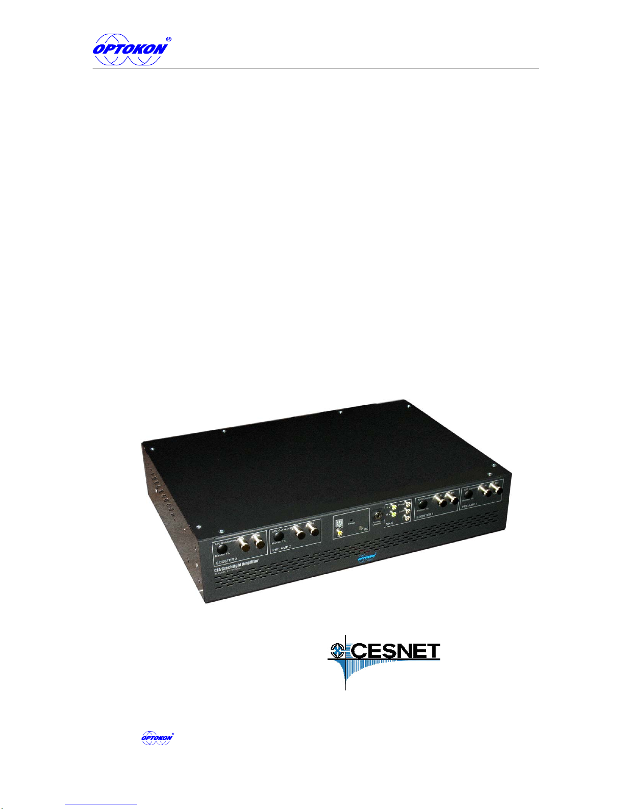
CLA - CZECHLIGHT AMPLIFIER
DEVICES
USER MANUAL
(PLEASE READ IT BEFORE USE)
Manufactured under the licence of
Revision 2.4
Page 2

EDFA optical amplifier – user manual
2
is the registered trademark of OPTOKON, a.s. Other names and trademarks mentioned
herein may be the trademarks of their respective owners
Manufactured under the licence of
All rights reserved. No parts of this work may be reproduced in any form or by any means - graphic, electronic,
or mechanical, including photocopying, recording, taping or information storage and retrieval systems - without
the written permission of the publisher.
Products that are referred to in this document may be either trademarks and/or registered trademarks of the
respective owners. The publisher and the author make no claim to these trademarks.
While every precaution has been taken in the preparation of this document, the publisher and the author
assume no responsibility for errors or omissions, or for damages resulting from the use of information
contained in this document or from the use of programs and source code that may accompany it. In no event
shall the publisher and the author be liable for any loss of profit or any other commercial damage caused or
alleged to have been caused directly or indirectly by this document.
OPTOKON, a.s.
Cerveny Kriz 250
586 02 Jihlava
Czech Republic
tel. +420 564 040 111
fax +420 564 040 134
WWW.OPTOKON.COM
Page 3

EDFA optical amplifier – user manual
3
Contents
1 Description of CLA amplifier ............................................................................ 5
2 General Information ......................................................................................... 6
2.1 Safety precautions .................................................................................... 6
2.2 Optical interface connection: .................................................................... 6
2.3 Laser classification ................................................................................... 7
3 Packaging and standard accessories .............................................................. 9
4 Technical specification................................................................................... 10
5 Basic configuration......................................................................................... 12
6 Mechanical design ......................................................................................... 13
6.1 Front panel ............................................................................................. 13
6.2 Display (only version with display -D-) .................................................... 14
6.3 Monitoring port (1% of output No. 1 power) ............................................ 15
6.4 Rear panel .............................................................................................. 15
7 Starting operation........................................................................................... 16
8 Communication with the device ..................................................................... 17
9 Command line................................................................................................ 18
Keyboard and monitor................................................................................... 18
Console......................................................................................................... 18
9.1 Before Login to the CLA ......................................................................... 18
9.2 Login to the CLA ..................................................................................... 19
9.3 IP address setting ................................................................................... 19
9.4 FIREWALL.............................................................................................. 21
9.5 FIREWALL START ................................................................................. 21
9.6 FIREWALL STOP ................................................................................... 21
9.7 CLA Admin ............................................................................................. 21
10 Web administrator interface ....................................................................... 23
10.1 IP address setting ............................................................................... 23
10.2 Connection to the CLA ........................................................................ 23
10.3 Summary............................................................................................. 24
Summary EDFA parameters ......................................................................... 24
Summary System information ....................................................................... 25
Summary Device parameters........................................................................ 25
Summary Network settings ........................................................................... 26
Summary Firewall settings ............................................................................ 26
10.4 Amplifier .............................................................................................. 27
Normal mode................................................................................................. 27
Expert mode.................................................................................................. 29
10.5 Health.................................................................................................. 31
10.6 Network............................................................................................... 32
Network properties ........................................................................................ 32
Firewall.......................................................................................................... 33
10.7 SNMP.................................................................................................. 34
10.8 Postman.............................................................................................. 35
10.9 Log ...................................................................................................... 36
10.10 System ................................................................................................ 37
Account properties ........................................................................................ 37
Page 4

EDFA optical amplifier – user manual
4
Base device information................................................................................ 38
Date and Time............................................................................................... 38
Web interface secure .................................................................................... 39
10.11 Restore ............................................................................................... 39
Backup and Restore configuration ................................................................ 39
CLA Reboot................................................................................................... 40
Load default settings and restart ................................................................... 40
10.12 Logout ................................................................................................. 41
10.13 Display password (optionally).............................................................. 41
11 Display ....................................................................................................... 42
Main menu .................................................................................................... 42
Main menu -> Overview ................................................................................ 42
Main menu -> Health..................................................................................... 42
Main menu -> Alarms .................................................................................... 43
Main menu -> Parameters............................................................................. 43
Main menu -> Parameters -> EDFA 1........................................................... 44
Main menu -> Parameters -> EDFA 1 S1...................................................... 44
Main menu -> Settings .................................................................................. 45
Main menu -> Settings -> EDFA settings ...................................................... 45
Main menu -> Settings -> EDFA settings -> EDFA 1 .................................... 46
Main menu -> Settings -> EDFA settings -> EDFA 1 S1 (Standard mode) ... 46
Main menu -> Settings -> EDFA settings -> Expert / Standard mode ........... 47
Main menu -> Settings -> Network settings................................................... 47
Main menu -> Settings -> Network settings -> Set display password............ 48
Main menu -> Screensaver ........................................................................... 48
Main menu -> Help and About ...................................................................... 48
12 Detailed EDFA Command set .................................................................... 49
13 EDFA education and Application note........................................................ 59
13.1 EDFA education .................................................................................. 59
What`s mean under term “EDFA”.................................................................. 59
EDFA block scheme...................................................................................... 59
EDFA Operational modes ............................................................................. 60
Operational mode settings example.............................................................. 60
13.2 Application note................................................................................... 61
14 Alarms ........................................................................................................ 62
15 Contacts: .................................................................................................... 63
Page 5

EDFA optical amplifier – user manual
5
1 Description of CLA amplifier
The CLA is a family of low noise, high performance EDFA designed to support cost
effective and turnkey amplification solutions for fiber optic networks. The CLA EDFA includes
2 in 1 Pre Amp and Booster EDFA. The electronic control board permits the separate control
of the 2 EDFAs.
Different control modes are available:
AGC (automatic gain control)
APC (automatic power control)
ACC (automatic current control) on each stage
Features:
Low noise figures
Wide wavelength range
Low power consumption
Microcomputer control system, including remote control
RS232 , Ethernet, USB interfaces, optionally GSM/GPRS, Wi-Fi
100-230V AC and/or 48V DC PSUs available
Multi channel amplification (e.g. long-haul DWDM)
Single channel amplification (e.g. CATV)
Booster / In-line / Preamp / CATV
LED signalization
Page 6

EDFA optical amplifier – user manual
6
2 General Information
2.1 Safety precautions
To ensure a high level of operator safety during installation, commissioning and operating
the equipment, as well as ensuring that the equipment remains undamaged, it is necessary
to consider the following general warnings.
Installation, commissioning, operation and service are only allowed to be
carried out by an authorised person:
Only a person trained in the safety of fiber optical systems can handle and
operate the equipment
The test equipment is intended for / to be used (safe extra low voltage) in this
environment only.
Use only standard or optional accessories supplied by your distributor
Use only the equivalent connector types to those built into the instrument in
order to avoid damage to the instrument components.
During storage and operation the equipment must be kept clean
Do not cover the ventilation holes
The PC ON/OFF switch located on the front controls the microcomputer
operation only. For total deactivation of the device use both switches located
at the rear
After a power outage the device will automatically restart at the previous
status
2.2 Optical interface connection:
Take note of the safety rules for lasers class 3b
Use only the relevant optical connectors
Optical connectors must be clean
Visual check of optical connectors using a 400x magnification microscope must
be performed before connection
In case the connectors are not perfectly clean – please clean them according to
the procedure described in the technical specification for the relevant
connectors
It is recommended to terminate the unused ports, specially CATV ve rsion, with
appropriate, terminators defined for max output power.
Please note, the integrated protective dust cap is not designed to eliminate
light emissions from output port.
Page 7

EDFA optical amplifier – user manual
7
2.3 Laser classification
A laser is a light source that can be dangerous to the people exposed to it. Even low power
lasers can be hazardous to eyesight. A person exposed to laser radiation (especially
invisible radiation) may be unaware that damage is occurring. Some lasers are so powerful
that even the diffuse reflection from a surface can be hazardous to the eye. Laser radiation
predominantly causes eye injury via thermal effects on the retina. A transient increase of
only 10 °C can destroy retinal photoreceptors
Lasers have been classified by wavelength and maximum output power into four classes
and a few subclasses since the early 1970s. The classifications categorize lasers according
to their ability to produce damage in exposed people, from class 1 (no hazard during
normal use) to class 4 (severe hazard for eyes and skin). There are two classification
systems, the "old system" used before 2002, and the "revised system" being phased in
since 2002. The latter reflects the greater knowledge of lasers that has been accumulated
since the original classification system was devised, and permits certain types of lasers to
be recognized as having a lower hazard than was implied by their placement in the original
classification system. The revised system is part of the revised IEC 60825 standard. From
2007, the revised system is also incorporated into the US-oriented ANSI Laser Safety
Standard (ANSI Z136.1). Since 2007, labeling according to the revised system is accepted
by the FDA on laser products imported into the US. The old and revised systems can be
distinguished by the 1M, 2M and 3R classes used only in the revised system and the 2A
and 3A classes used only in the old system. Class numbers were designated using Roman
numerals (I–IV) in the US under the old system and Arabic numerals (1–4) in the EU. The
revised system uses Arabic numerals (1–4) in all jurisdictions.
The classification of a laser is based on the concept of accessible emission limits (AEL) that
are defined for each laser class. This is usually a maximum power (in W) or energy (in J)
that can be emitted in a specified wavelength range and exposure time. For infrared
wavelengths above 4 μm, it is specified as a maximum power density (in W/m2). It is the
responsibility of the manufacturer to provide the correct classification of a laser, and to
equip the laser with appropriate warning labels and safety measures as prescribed by the
regulations. Safety measures used with the more powerful lasers include key-controlled
operation, warning lights to indicate laser light emission, a beam stop or attenuator, and
an electrical contact that the user can connect to an emergency stop or interlock
Below, the main characteristics and requirements for the classification system from 2002
are listed, along with typical required warning labels. Additionally, classes 2 and higher
must have the triangular warning label shown here and other labels are required in specific
cases indicating laser emission, laser apertures, skin hazards, and invisible wavelengths
Class 1
A class 1 laser is safe under all conditions of normal use. This means the maximum
permissible exposure (MPE) cannot be exceeded. This class includes high-power lasers
within an enclosure that prevents exposure to the radiation and that cannot be opened
without shutting down the laser. For example, a continuous laser at 600 nm can emit up to
0.39 mW, but for shorter wavelengths, the maximum emission is lower because of the
potential of those wavelengths to generate photochemical damage. The maximum
emission is also related to the pulse duration in the case of pulsed lasers and the degree of
spatial coherence.
Page 8

EDFA optical amplifier – user manual
8
Class 1M
A Class 1M laser is safe for all conditions of use except when passed through magnifying
optics such as microscopes and telescopes. Class 1M lasers produce large-diameter beams,
or beams that are divergent. The MPE for a Class 1M laser cannot normally be exceeded
unless focusing or imaging optics are used to narrow the beam. If the beam is refocused,
the hazard of Class 1M lasers may be increased and the product class may be changed. A
laser can be classified as Class 1M if the total output power is below class 3B but the
power that can pass through the pupil of the eye is within Class 1.
Class 2
A Class 2 laser is safe because the blink reflex will limit the exposure to no more than 0.25
seconds. It only applies to visible-light lasers (400–700 nm). Class-2 lasers are limited to 1
mW continuous wave, or more if the emission time is less than 0.25 seconds or if the light
is not spatially coherent. Intentional suppression of the blink reflex could lead to eye injury.
Many laser pointers are class 2.
Class 2M
A Class 2M laser is safe because of the blink reflex if not viewed through optical
instruments. As with class 1M, this applies to laser beams with a large diameter or large
divergence, for which the amount of light passing through the pupil cannot exceed the
limits for class 2.
Class 3R
A Class 3R laser is considered safe if handled carefully, with restricted beam viewing. With
a class 3R laser, the MPE can be exceeded, but with a low risk of injury. Visible continuous
lasers in Class 3R are limited to 5 mW. For other wavelengths and for pulsed lasers, other
limits apply.
Class 3B
A Class 3B laser is hazardous if the eye is exposed directly, but diffuse reflections such as
from paper or other matte surfaces are not harmful. Continuous lasers in the wavelength
range from 315 nm to far infrared are limited to 0.5 W. For pulsed lasers between 400 and
700 nm, the limit is 30 mJ. Other limits apply to other wavelengths and to ultrashort
pulsed lasers. Protective eyewear is typically required where direct viewing of a class 3B
laser beam may occur. Class-3B lasers must be equipped with a key switch and a safety
interlock.
Class 4
Class 4 lasers include all lasers with beam power greater than class 3B. In addition to
posing significant eye hazards, with potentially devastating and permanent eye damage as
a result of direct beam viewing, diffuse reflections are also harmful to the eyes within the
distance called the Nominal Hazard Zone. Class 4 lasers are also able to cut or burn skin.
In addition, these lasers may ignite combustible materials, and thus represent a fire risk, in
some cases. Class 4 lasers must be equipped with a key switch and a safety interlock.
Page 9

EDFA optical amplifier – user manual
9
3 Packaging and standard accessories
Standard accessories
1x CLA amplifier, type according to request
2x Unit Holders (rack mount kit)
2x Power supply cable
2x Key
1x UTP cable
1x User Manual
Page 10

EDFA optical amplifier – user manual
10
4 Technical specification
Basic parts
1 or 2 EDFA modules, each contain 1 or 2 amplifiers, in total from 1 to 4
amplifiers
dual power supply units (PSU)
single board PC based microcomputer
Design
standard 2U rack case, size 430 x 300 x 88 mm (W x D x H)
standard 1U rack case, size 435 x 540 x 44 mm (W x D x H)
dual PSUs for redundancy
PSU versions of 100-230 V AC or 48 V DC, maximum consumption 150 W, typical
consumption 50 W
Control
Based on (OS) Linux operating system
Available interfaces
wired: RS-232, Ethernet
wireless: GSM/GPRS/UMTS, Wi-Fi, BlueTooth
Tools for remote management
command line interface (CLI) via SSH, SNMP
critical warnings are sent via e-mail, SNMP Traps can be generated
all important operational parameters are monitored (input and output powers,
alarms, laser diode currents, temperatures, voltages, fan speeds,...)
Basic CLA types
CLA types for amplification of high channel counts (with flat gain characteristics)
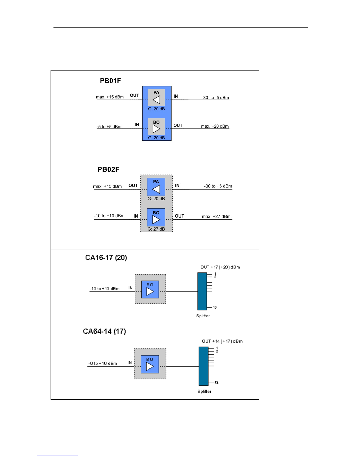
PB01F: low noise preamplifier and booster (20 dBm)
PB02F: low noise preamplifier and high power booster (27 dBm)
DI01F: dual inline amplifier
CLA types for single or low channel counts (without flat gain)
PB01: low noise preamplifier and booster (19 dBm)
PB02: low noise preamplifier and high power booster (27 dBm)
DI01: dual inline amplifier
CLA types for CATV application
CA16: 16 output ports CATV amplifier
CA64: 64 output ports CATV amplifier
Booster, inline and preamplifiers
EDFA modules may be selected to best fit your applications
Further CLA types can be tailored to exactly meet your requirements, concerning
different applications and channel counts.
Page 11
EDFA optical amplifier – user manual
11
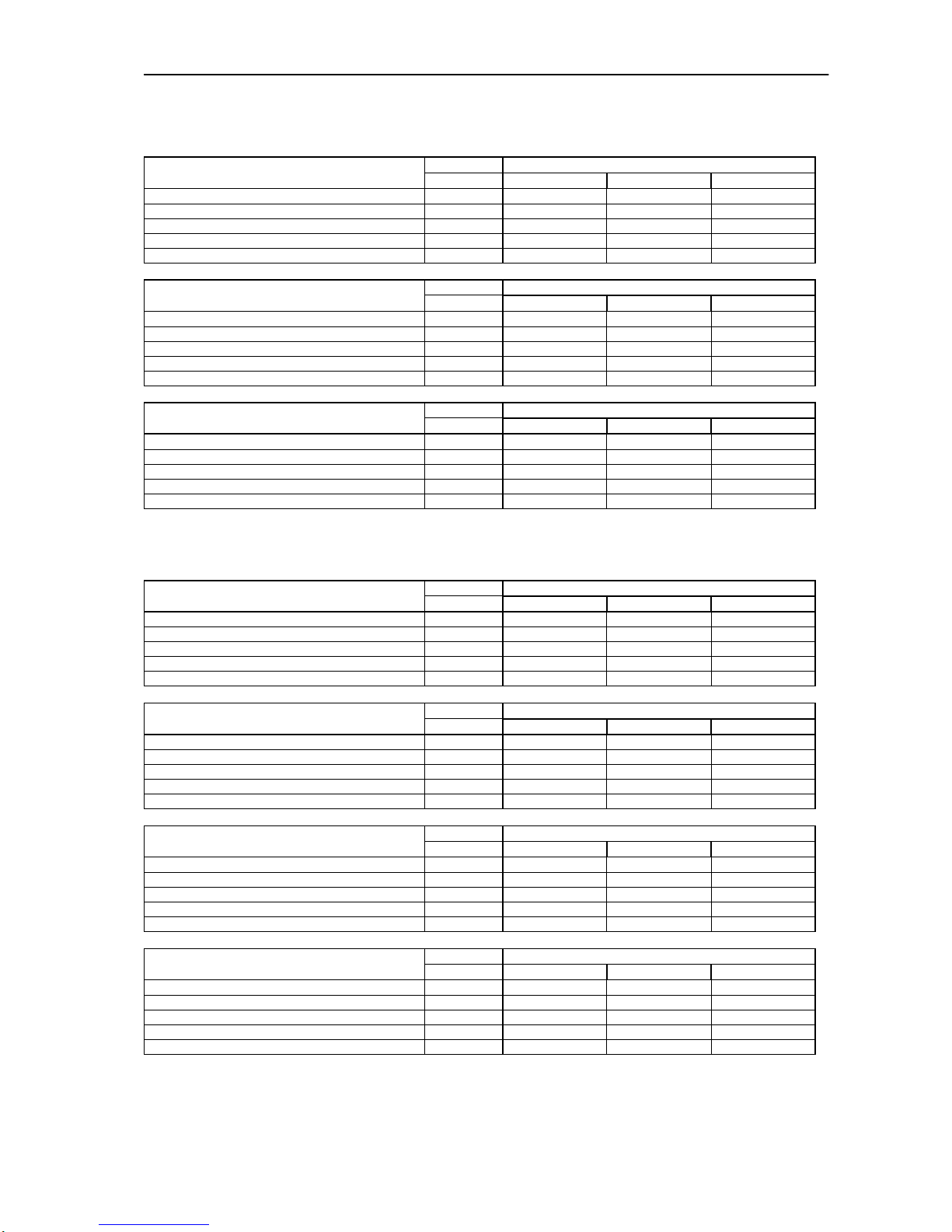
Optical characteristics of multi-channel amplifiers (with flat gain
characteristics)
Unit Specifications
Pre and In-line Flat Gain Amplifier
Parameters
MIN TYP MAX
Signal Wavelength nm 1535 1565
Input optical power dBm -30 -5
Nominal Gain dB 20
Saturated output power (only signal) dBm + 15
Noise figure dB 4.3 4.8
Unit Specifications Booster Flat Gain Amplifier 20 dBm
Parameters
MIN TYP MAX
Signal Wavelength nm 1535 1565
Input optical power dBm -5 0 5
Nominal Gain dB 20
Saturated output power (only signal) dBm + 20
Noise figure dB 6
Unit Specifications Booster Flat Gain Amplifier 27 dBm
Parameters
MIN TYP MAX
Signal Wavelength nm 1535 1565
Input optical power dBm -10 0 10
Nominal Gain dB 27
Saturated output power (only signal) dBm + 27
Noise figure dB 6
Optical characteristics of single channel amplifiers (without flat gain
characteristics)
Unit Specifications PreAmplifier
Parameters
MIN TYP MAX
Signal Wavelength nm 1535 1565
Input optical power dBm -40 -20
Nominal Gain dB 35
Saturated output power (only signal) dBm + 5
Noise figure dB 4 4.5
Unit Specifications In-line Amplifier
Parameters
MIN TYP MAX
Signal Wavelength nm 1535 1565
Input optical power dBm -30 -5
Nominal Gain dB 30
Saturated output power (only signal) dBm + 15
Noise figure dB 4.3 4.8
Unit Specifications Booster Amplifier 20 dBm
Parameters
MIN TYP MAX
Signal Wavelength nm 1535 1565
Input optical power dBm -5 0 5
Nominal Gain dB 20
Saturated output power (only signal) dBm + 20
Noise figure dB 6
Unit Specifications Booster Gain Amplifier 27 dBm
Parameters
MIN TYP MAX
Signal Wavelength nm 1535 1565
Input optical power dBm -10 0 10
Nominal Gain dB 27
Saturated output power (only signal) dBm + 27
Noise figure dB 6
Optical parameters are predefined values; parameters can be customized on demand.
Page 12
EDFA optical amplifier – user manual
12
5 Basic configuration
Block diagram
Page 13
EDFA optical amplifier – user manual
13
6 Mechanical design
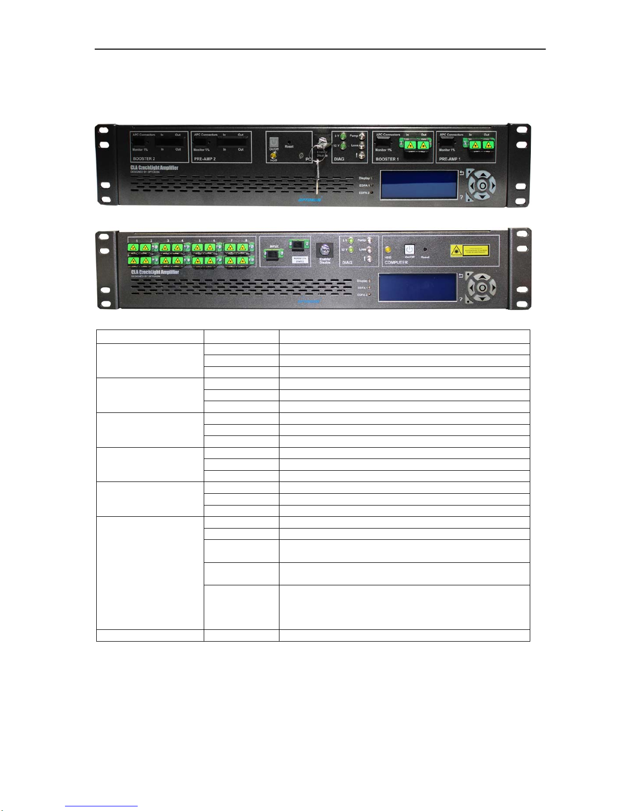
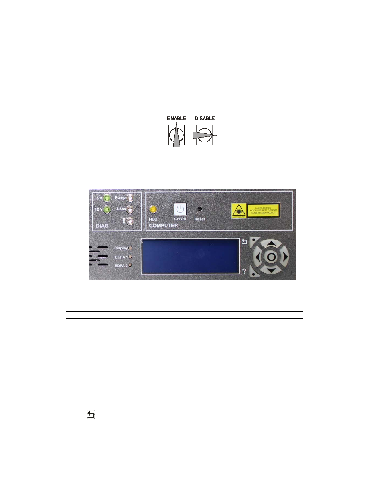
6.1 Front panel
CLA-PB01F-NSC-D-AC
CLA-CA16-20-NSC-M-D-AC
Block on the panel Legend Description
IN Pre-Amplifier 1 Input
OUT Pre-Amplifier 1 Output
PRE-AMP 1
Monitor 1% Monitor of Pre-Amplifier 1 input (optionally)
IN Booster Amplifier 1 Input
OUT Booster Amplifier 1 Output
BOOSTER 1
Monitor 1% Monitor of Booster Amplifier 1 input (optionally)
IN Pre-Amplifier 2 Input
OUT Pre-Amplifier 2 Output
PRE-AMP 2
Monitor 1% Monitor of Pre-Amplifier 2 input (optionally)
IN Booster Amplifier 1 Input
OUT Booster Amplifier 1 Output
BOOSTER 2
Monitor 1% Monitor of Booster Amplifier 1 input (optionally)
ON/OFF ON/OFF button PC
Reset Reset button PC
COMPUTER
HDD HDD LED PC
5V Green LED indicates 5V
12V Green LED indicates 12V
Pump
Blue LED indicates active pump diode – the amplified
optical signal is at the output ports
Loss
Yellow LED indicates LOSS of input/output power alarm
(chapter 13)
DIAG.
!
RED LED indicates EDFA critical alarm –
temperature of pumping diodes or module is out of
range, the pumping current exceeds limit for end of
life current (chapter 13)
KEY Enable/Disable Amplifier ENABLE/DISABLE
WARNING:
Use only APC connectors (chapter 2.2)
Optical connector must be clean (chapter 2.2)
In case of active RED LED (EDFA alarm) - switch KEY to the Disable
position.
Page 14
EDFA optical amplifier – user manual
14
NOTE:
The EDFA units contain internal memory, they can work independently of
PC function
Green LEDs 5V and 12V indicate internal power supply voltage
Yellow LED indicates EDFA LOSS alarm. The limits shall be set - by
commands LI, LO, see chapter 8, 9, 10)
Key switch position:
Enable or disable EDFA function. Enable – Pump diode ON, Disable – Pump
diode OFF. This setting has effect to ADI alarm (chapter 13)
6.2 Display (only version with display -D-)
Legend Description
Display If LED blinks, the Display module is function
EDFA 1 Present active EDFA unit
Don`t light – the EDFA unit without alarms, don´t active the pump
diode
Green light – the EDFA unit without alarms, active the pump diode
Red light – the EDFA unit report some alarms
(e.g. ADI, LI or LO alarm, see in chapter 13)
EDFA 2 Present active EDFA unit
Don`t light – the EDFA unit without alarms, don´t active the pump
diode
Green light – the EDFA unit without alarms, active the pump diode
Red light – the EDFA unit report some alarms
(e.g. ADI, LI or LO alarm, see in chapter 13)
?
Quick help
One step back
Page 15
EDFA optical amplifier – user manual
15
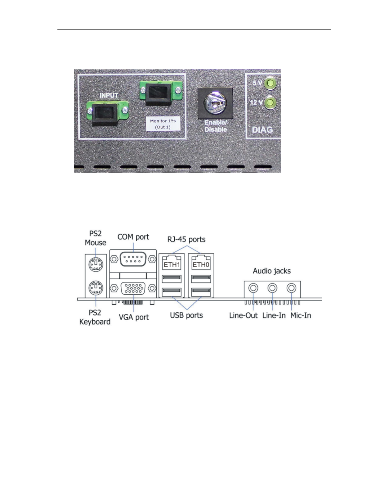
6.3 Monitoring port (1% of output No. 1 power)
6.4 Rear panel
Page 16

EDFA optical amplifier – user manual
16
7 Starting operation
Switching on procedure - step by step
Please check the completeness of the product during unpacking
Mount the unit holder – rack mount installation kit on both sides of the amplifier
box
Install the CLA box into the rack
Connect the power supply cable into any power supply socket on the rear panel
Connect the UPS cable into second power supply socket
When you need to change the setting of the optical amplifier – connect to the
CLA according to the description in Chapter 7.
Switch both switches on the power supply sockets ON.
After switching ON – the CLA will start the operation
Initialization of the CLA module starts independently of the PC function.
After finishing all initialization processes, the CLA settings can be changed
according to the description in Chapter 8, 9, 10.
Page 17

EDFA optical amplifier – user manual
17
8 Communication with the device
Two available communications with the device:
Command line – chapter 8
Web interface (user friendly) – chapter 9
Optionally - Display module with control keyboard – chapter 10
Page 18

EDFA optical amplifier – user manual
18
9 Command line
Communication via command line is not very user friendly and user needs know
basic command for Linux OS.
Use command line for basic Ethernet configuration only!
If user can´t work in Linux OS, we advice use Web interface!
For access to the device via command line use:
a) Keyboard & Monitor (ports on the motherboard)
b) Optional console (serial port on the motherboard, 115200, N, 1)
Keyboard and monitor
Switch OFF PC by PC ON/OFF button or switch both switches on the power
supply sockets OFF
Connect the keyboard and the monitor into the corresponding sockets on the
rear panel.
Switch ON CLA by switches on the power supply units or switch ON PC by PC
ON/OFF button
The access to the CLA modules is established through PC station now.
Console
Use Lap-Link Cable (CLA accessories) and connect it to the corresponding
socket at the rear panel of CLA.
Connect the Lap-Link cable to the your computer
Run Hyperterminal software
Hyperterminal is standard software component of each operating system Windows 98, XP, Vista
Run Hyperterminal by command “hypertrm”
Set Hyperterminal configuration:
Bits per second 115200
Data bits 8
Parity None
Stop bits 1
Flow control None
Press button “Enter”
9.1 Before Login to the CLA
Before login to the CLA is necessary know that all changes made in file
system are stored in the RAM memory only. To save the changes of settings
in the file system of CLA you have to execute the command
savechanges
NOTE: if you don´t use command “savechanges”, all your changes will be lost after restart PC.
Page 19

EDFA optical amplifier – user manual
19
9.2 Login to the CLA
After the PC is switched on you can login to your CLA system. Type login and
password
Factory setting of login:
Login: root
Password: optokon
NOTE: for change of password use command “passwd”
After login to the CLA, system displays the MOTD message “Message Of The
Day”
Message Description Parameter
Serial Number:
Serial number of device
SERIAL
Device:
Type of device
DEVICE_TYPE
CLDDistro ver.:
Software distribution version
VERSION
Location:
Location of the CLA
LOCATION
Line:
Trace from to
LINE
Admin:
Administrator name
ADMIN
Administrator email
ADMIN_EMAIL
Administrator phone
ADMIN_PHONE
To change the default MOTD the following procedure shall be used:
Edit file /etc/motd.sheet
Run file /etc/init.d/cld-motd
Display new MOTD cat /etc/motd
9.3 IP address setting
For change or setting of IP address use file /etc/network/interfaces.
In this file you can set IP addresses of all network cards
Default Ethernet setting:
NET_IP 192.168.0.10
NET_MASK 255.255.255.0
NET_GATEWAY 192.168.0.1
ifconfig eth0
Example of file for functionally interface eth1 with static IP address:
allow-hotplug eth0
auto eht0
iface eth0 inet static
address 192.168.123.123
netmask 255.255.255.0
gateway 192.168.123.255
NOTE: the attribute “#“ means commentary
Page 20

EDFA optical amplifier – user manual
20
You can use also JOE editor for settings ETH0 as below
joe /etc/network/interfaces
For JOE editor HELP press
ctrl-k h
For SAVE and EXIT JOE editor press
ctrl-k x
For EXIT without SAVE JOE editor press
ctrl-c
To apply the change to the system the execute command shall be used
/etc/init.d/networking restart
WARNING: User has to heed for remote execute this command. After running this
command the network interface card is not available and if any mistake is in the
configuration file the network connection will not work.
Page 21
EDFA optical amplifier – user manual
21
9.4 FIREWALL
The FIREWALL is running on the CLA permanently and all communication is
disabled. To make the changes the firewall configuration file shall be used:
/etc/czech-light/firewall.conf
The file contains simple table with IP addresses which allow communication
with the CLA only via Ethernet 0 (eth0).
NOTE: the attribute “#“ means commentary
9.5 FIREWALL START
After firewall configuration enable firewall system with help command
/etc/init.d/firewall start
9.6 FIREWALL STOP
In some cases is important stop firewall. For example in the case where user
set firewall with bad configuration and after this configuration he can`t connect to
the CLA. For stopping the firewall system use following command
/etc/init.d/firewall stop
9.7 CLA Admin
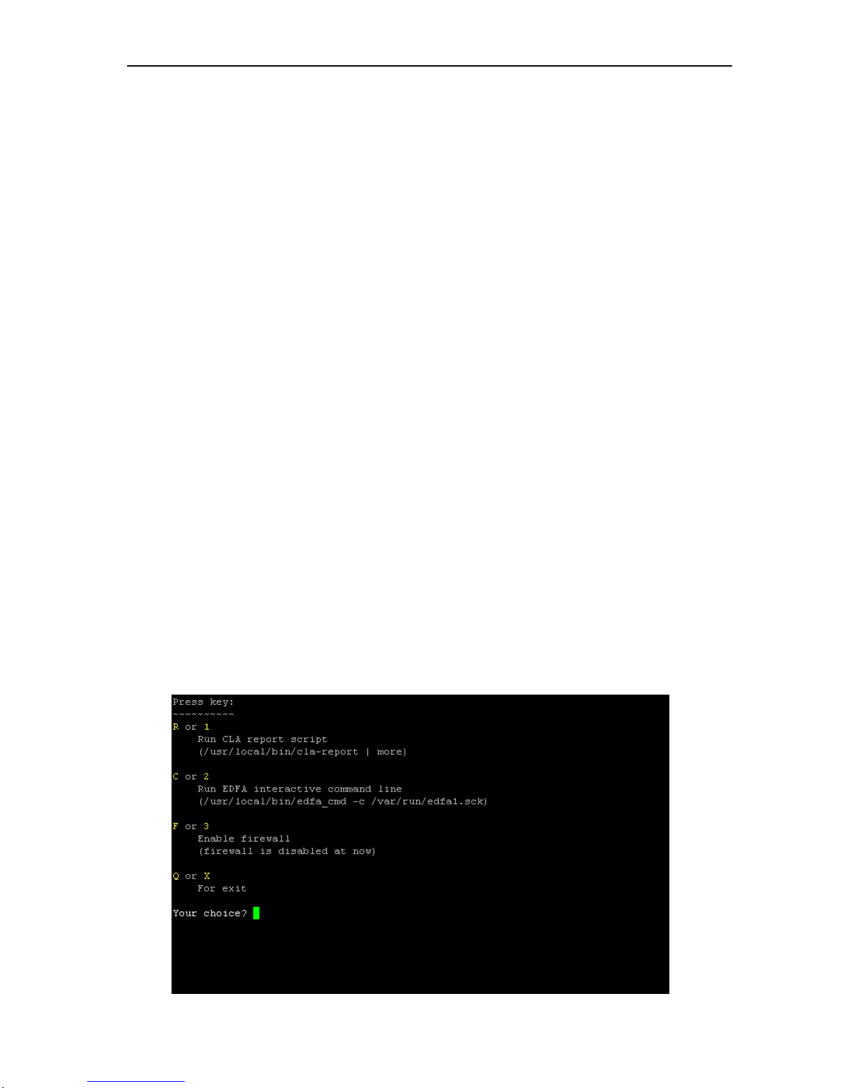
The CLA Admin is console for configuration of the EDFA unit. For running type
command:
cla-admin
Page 22
EDFA optical amplifier – user manual
22
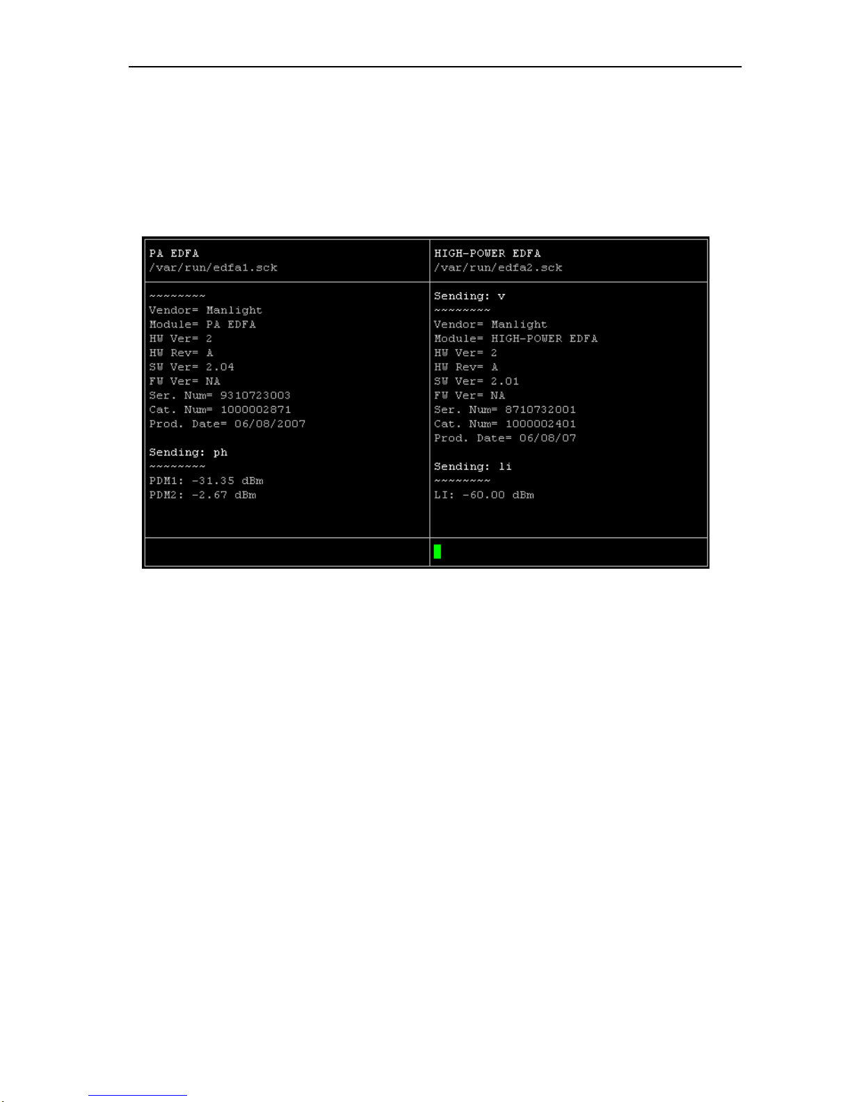
Point 1 CLA report script:
CLA report is an application to display the main parameters of all EDFA units
in the CLA device. This is the best tool for first monitoring of actual CLA status.
Point 2 Run EDFA interactive command line:
Run terminal for configuration of the EDFA unit. The detailed commands for
configuration of the EDFA unit are placed in chapter 11.
Point 3 FIREWALL:
This choose allows enable or disable firewall system.
Point 4 Quit:
Exit from administrative console
Page 23

EDFA optical amplifier – user manual
23
10 Web administrator interface
10.1 IP address setting
The CLA device contains default setting for ETH0
NET_IP 192.168.0.10
NET_MASK 255.255.255.0
NET_GATEWAY 192.168.0.1
For connection set on your PC IP address e.g. 192.168.0.11 with same mask
255.255.255.0
Use for connection UTP cable (CLA accessories) to the CLA and to your PC.
10.2 Connection to the CLA
Run a web browser (Internet Explorer, Opera, Mozilla etc.) and use https
protocol.
Default address for connection to the CLA:
https://192.168.0.10/
Note: The certificate will not be valid probably. User can load its certificate later via web
interface (chapter 9.10 System).
Available two login accounts:
Administrator Standard USER
Username: admin Username: user (1)
Password: claadmin (2) Password: clauser (2)
Available area:
SUMMARY
AMPLIFIER
HEALTH
NETWORK
SNMP
POSTMAN
LOG
SYSTEM
RESTORE
Available area:
SUMMARY
*1 User account is disabled – enable user account by web interface (chapter 9.10 System).
*2 Password is changeable by web interface (chapter 9.10 System).
Page 24
EDFA optical amplifier – user manual
24
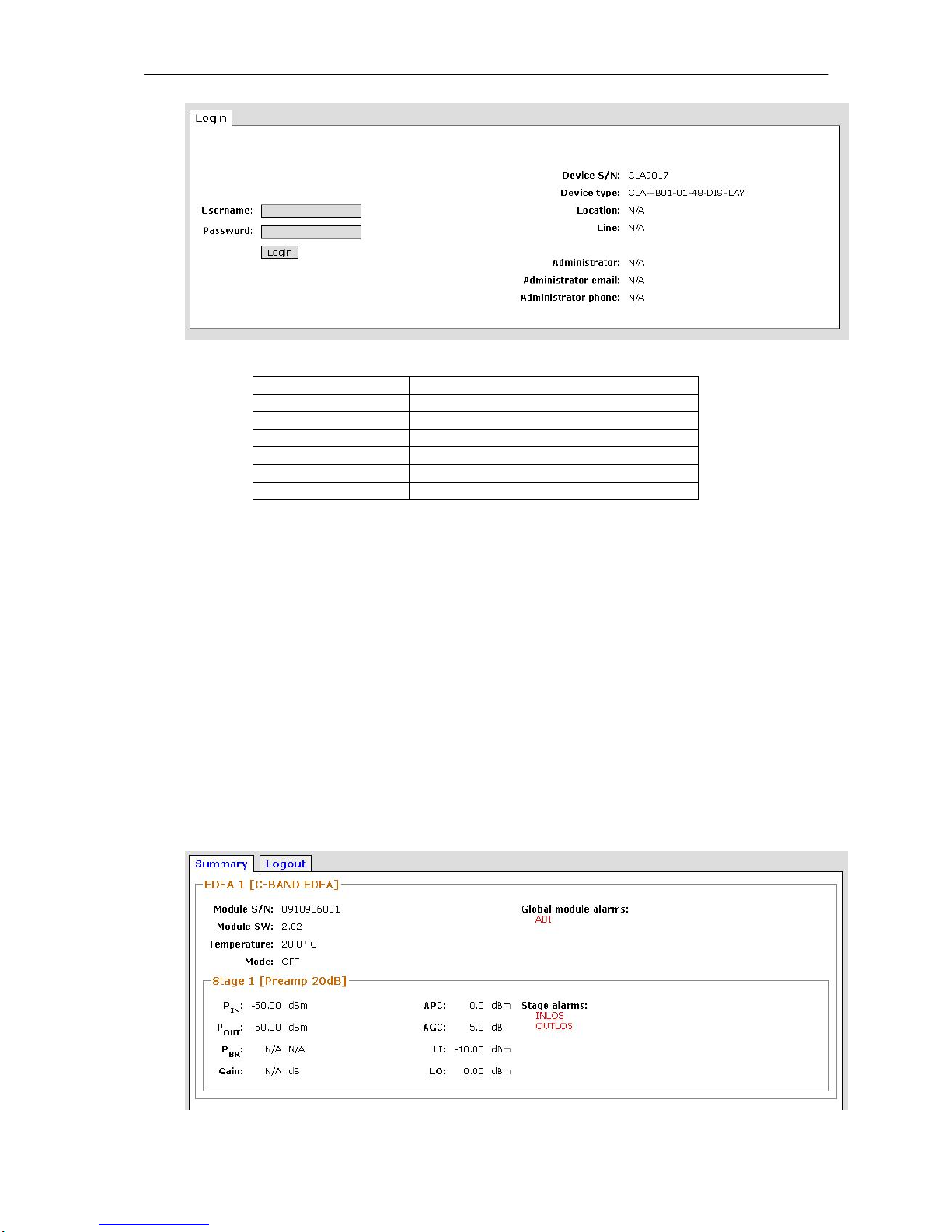
Picture 1 - Login to the CLA
Device S/N
Serial number of the CLA
Device type
Type of the CLA
Location
Location or Placing to the CLA (e.g. City)
Line
Name of optical trace
Administrator
Administrator name
Administrator email
Email to Administrator
Administrator phone
Phone to Administrator
Table 1 - Login to the CLA
These basic parameters are changeable by web interface (chapter 9.10
System)
10.3 Summary
This component part is available by admin and user account.
The summary component part contains basic status of optical amplifier. This
component part enable READ basic parameters only.
EDFA unit parameters – SN, Pin, Pou, Temperatures, ALARMS
System information – CLA SN, Type, etc.
Device parameters – Voltage, Fan speed
Network settings
Firewall settings
Summary EDFA parameters
Picture 2 - Summary EDFA parameters
Page 25
EDFA optical amplifier – user manual
25
Module S/N
Serial number of EDFA unit
Module SW
Software version of EDFA unit
Temperature
EDFA unit case temperature
Mode
Operational EDFA unit mode (chapter 9.4)
Global module alarms
Global CLA alarms
Pin
Input optical level [dBm]
Pout
Output optical level [dBm]
Pbr
Back reflection on output connector [dBm]
Gain
Actual gain [dB]
APC
APC mode configuration (chapter 9.4)
AGC
AGC mode configuration (chapter 9.4)
LI
Threshold value of Loss input alarm [dBm]
LO
Threshold value of Loss output alarm [dBm]
Stage alarms
EDFA unit alarm for each stage (chapter 9.4)
Table 2 - Summary EDFA parameters
Summary System information
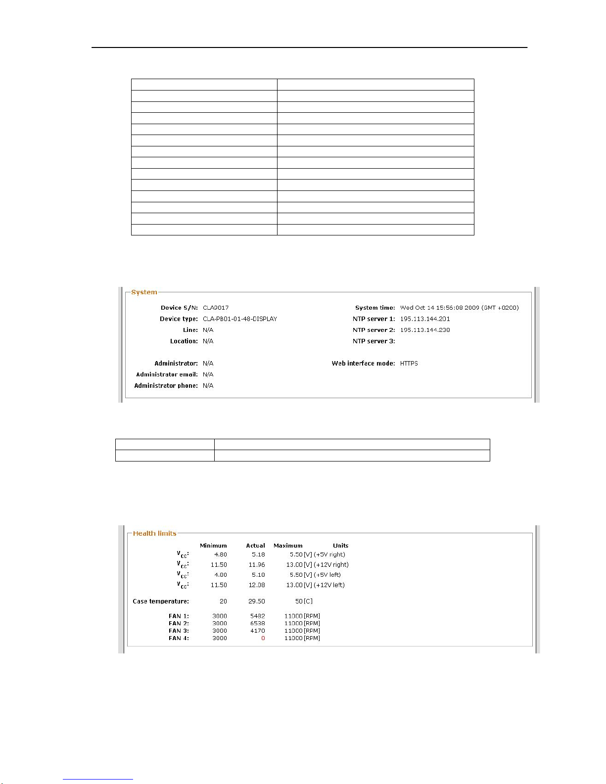
Picture 3 - Summary System information
Web interface mode
Choice web interface mode, HTTPS, HTTP, etc. (chapter 9.10)
Others items
See in chapter 9.2 Table 1
Table 3 - Summary System information
System information changeable in part System (chapter 9.10)
Summary Device parameters
Picture 4 - Summary Device parameters
Page 26
EDFA optical amplifier – user manual
26
Minimum
Threshold value for alarm (chapter 9.4)
Actual
Actual measured value
Maximum
Threshold value for alarm (chapter 9.4)
VCC
Output voltage form power supply units [V]
Case temperature
CLA case temperature
FAN 1
Right power supply unit – Fan speed
FAN 2
Left power supply unit – Fan speed
FAN 3
Internal FAN for EDFA units cooling
FAN 4
Unassigned
Table 4 - Summary Device parameters
Summary Network settings
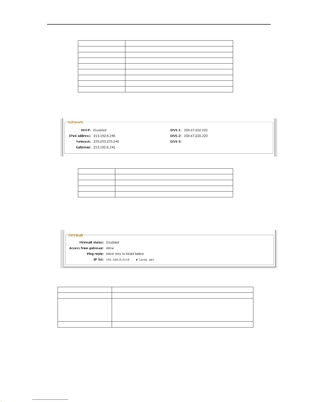
Picture 5 - Summary Network settings
DHCP
Enabled or Disabled IP address for DHCP server
IPv4 address
Fixed IP address version 4
Netmask
Mask of Subnet
Gateway
Gateway IP address
DNS
DNS server IP address
Table 5 - Summary Network settings
Network configuration in part Network (chapter 9.6)
Summary Firewall settings
Picture 6 - Summary Firewall settings
Firewall status
Enabled or Disabled Firewall function
Access from gateway
Allow or Denied access from gateway
Ping reply
Allow ping to the device
Allow only to listed below
Allow for all
Denied
IP list
List of allowed IP address for connection to the CLA
Table 6 - Summary Firewall settings
Firewall configuration in part Network (chapter 9.6)
Page 27
EDFA optical amplifier – user manual
27
10.4 Amplifier
This component part is available by admin account only.
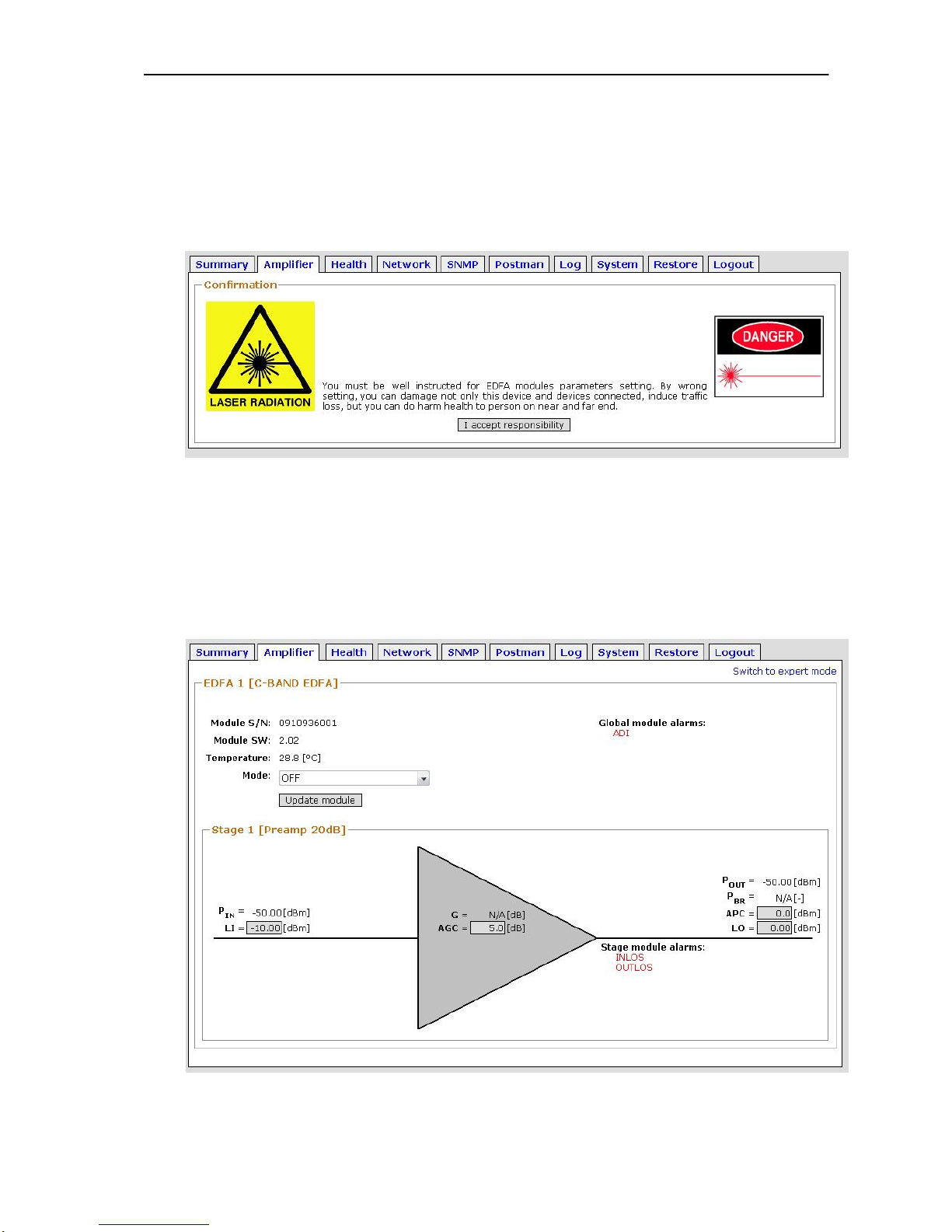
Administrator must accept responsibility before changing of optical parameters.
Before adjustable of EDFA unit, read chapter 2.
Picture 7 - Accept responsibility
The component part “Amplifier” allows change optical parameters of EDFA unit
and include two modes for setting Normal mode and Expert mode (for skilled
person only).
Switching between Normal and Expert mode is placed in upper right corner of
this component part.
Normal mode
Picture 8 - Normal mode
Page 28
EDFA optical amplifier – user manual
28
MODE
Choice of actual mode
OFF mode
AGC mode
APC mode
LI
Threshold value for Loss input alarm
AGC
Setting APC mode / Set constant output power
APC
Setting AGC mode / Set constant gain
LO
Threshold value for Loss output alarm
Table 7 - Normal mode - adjustable values
For accept your changes must click to button “Update module”
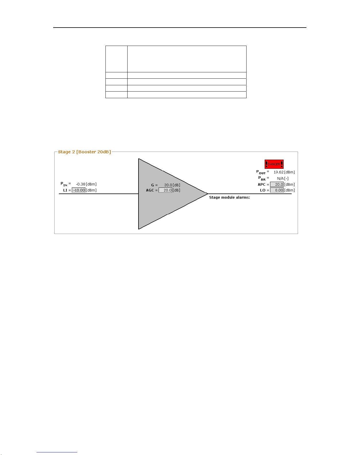
NOTE: if optical output level is higher than +10dBm is displayed by EDFA unit
logo “!DANGER!”. This is only warning report about high optical output level.
Picture 9 – DANGER report
Page 29
EDFA optical amplifier – user manual
29
Expert mode
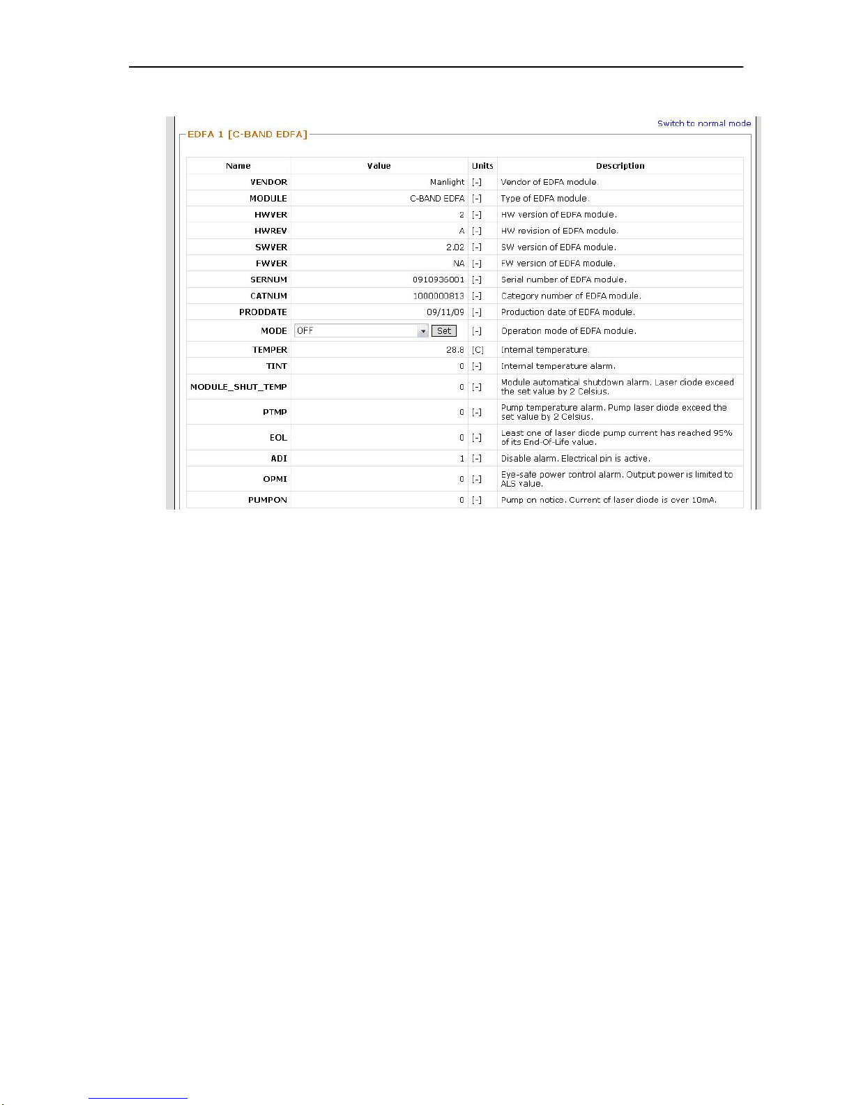
Picture 10 - Expert mode generally
Administrator can change operation mode of EDFA module in this part. For
accept the change click to “Set” button.
Other parameters are for reading only and their meaning are wrote in the
column “Description”.
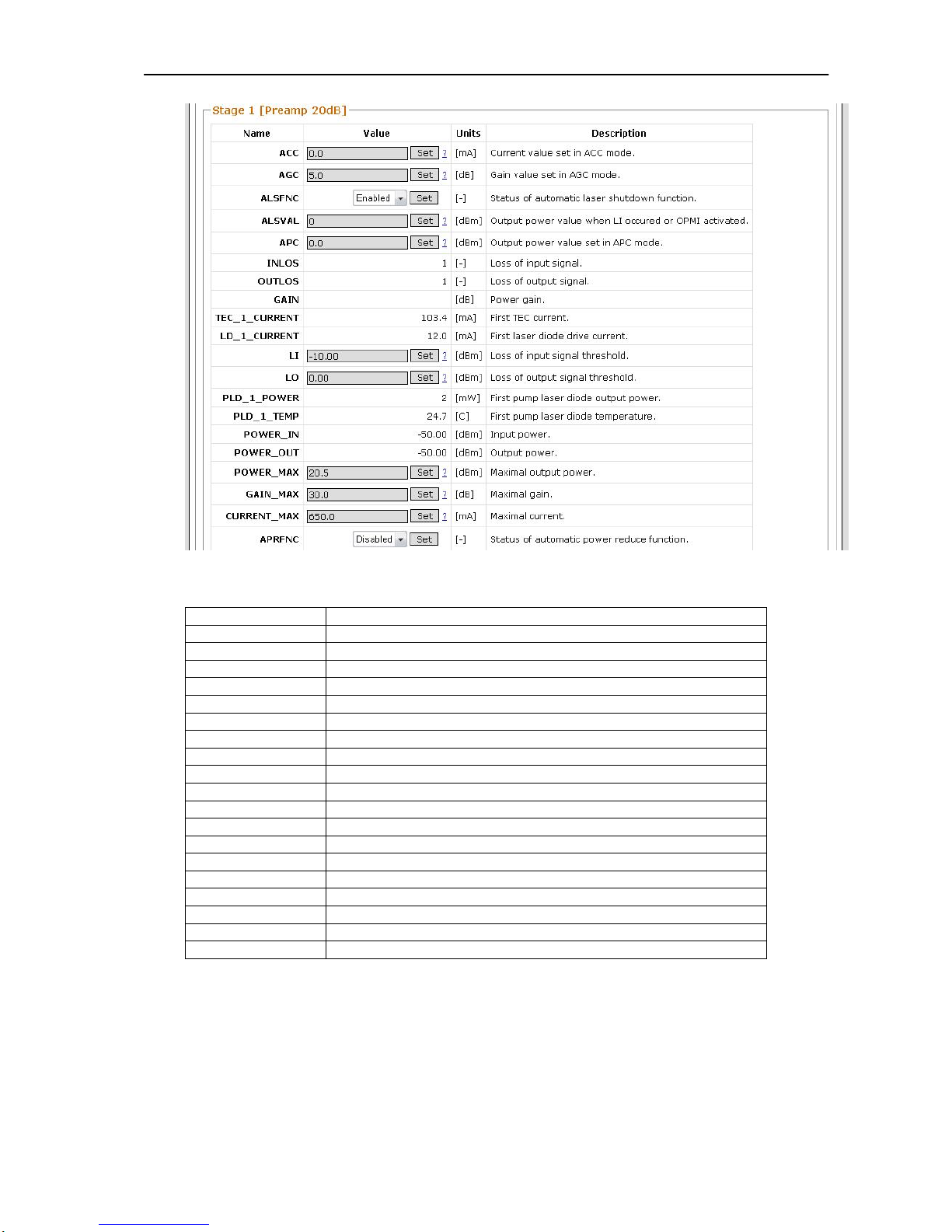
All others parameters of expert mode adjustable in next part called “Stage X”
(picture 10).
Page 30
EDFA optical amplifier – user manual
30
Picture 11 - Expert mode setting
ACC
Setting ACC mode / setting current of Pump diode [mA]
AGC
Setting AGC mode / setting constant Gain [dB]
ALSFNC
Enabled or Disabled Laser shutdown function
ALSVAL
Setting output power value when Loss input alarm is active [dBm]
APC
Setting APC mode / setting constant Output power [dBm]
INLOS
Loss of input alarm – 1 Active / 0 Not active
OUTLOS
Loss of output alarm – 1 Active / 0 Not active
GAIN
Actual gain report [dB]
TEC_1_CURRENT
Temperature control current [mA]
LD_1_CURRENT
First pump diode current [mA]
LI
Setting threshold value Loss of input alarm [dBm]
LO
Setting threshold value Loss of output alarm [dBm]
PLD_1_POWER
Output power from pump diode [mW]
PLD_1_TEMP
Pump diode Temperatures [°C]
POWER_IN
Input optical power [dBm]
POWER_OUT
Output optical power [dBm]
POWER_MAX
Set maximal output power [dBm] – protect EDFA unit
GAIN_MAX
Set maximal gain [dB] – protect EDFA unit
CURRENT_MAX
Set maximal pump diode current [mA] – protect EDFA unit
APRFNC
Enable or Disable Auto power reduce function
Table 8 - Expert mode
Page 31
EDFA optical amplifier – user manual
31
10.5 Health
This component part is available by admin account only.
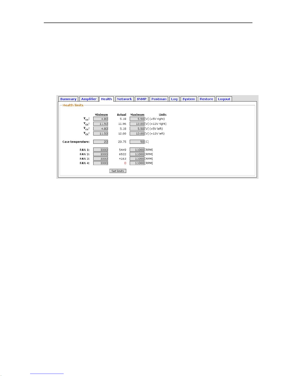
Health component is adopted from standard PCs BIOS systems. The Health
involves voltage values of power supply units and fans speed only. Admin can set
alarm thresholds (Minimum and Maximum). If an actual value is out of range,
alarm is activated and it can be send as warning mail to administrator (this function
is adjustable in part “Postman”.
Picture 12 - Health limits
Note: For disabling fans speed alarms type to minimum value “-1”.
Page 32
EDFA optical amplifier – user manual
32
10.6 Network
This component part is available by admin account only.
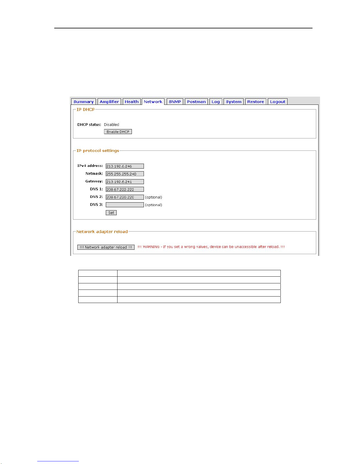
Administrator can in the part Network set network properties and firewall
Network properties
Picture 13 - Network properties
DHCP status
Enable or Disable read IP address from DHCP server
IPv4 address
Fixed IP address
Netmask
Mask of subnet
Gateway
IP address of Gateway
DNS
IP address of Domain Name Server
Table 9 - Network properties
NOTICE: For accept network change click to button “Network adapter reload”
WARNING: Check your new changes in network properties. If you set a wrong
values, device can`t accessible after reload.
Page 33
EDFA optical amplifier – user manual
33
Firewall
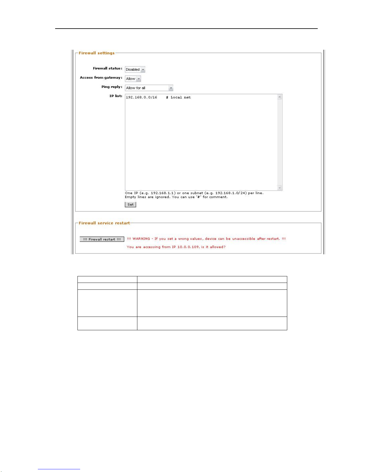
Picture 14 – Firewall
Firewall status
Enable or Disable Firewall function
Access from gateway
Allow or Denied access from gateway to the device
Ping reply
Allow or Denied ping to the device
Allow only to listed below
Allow for all
Denied
IP list
To this part type all IP address, which can connect to the
device by Enable firewall
Table 10 – Firewall
For accept change in IP list click to button “Set”
NOTICE: For accept changes in firewall system click to button “Firewall restart”
WARNING: Check your new changes in Firewall application. If you set a wrong
values, device can`t accessible after Firewall restart.
Page 34
EDFA optical amplifier – user manual
34
10.7 SNMP
This component part is available by admin account only.
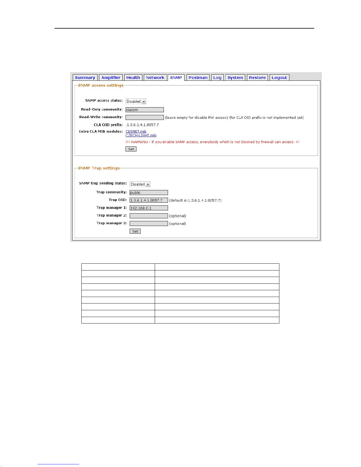
Picture 15 – SNMP
SNMP access setting
Enable or Disable SNMP function
Read-Only community
Name for Read Only community
Read-Write community
Read Write community isn`t implemented yet
CLA OID prefix
Is permanent
Extra CLA MIB modules
Permanent EXTRA CLA MIB modules
SNMP trap sending status
Enable or Disable trap sending
Trap community
Type of trap community
Trap OID
Trap number OID
Trap manager 1
IP address of Trap server
Picture 16 – SNMP
Page 35
EDFA optical amplifier – user manual
35
10.8 Postman
This component part is available by admin account only.
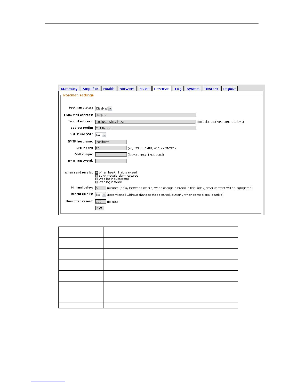
The postman service can send warning email according to administrator
settings. Administrator can Enabled or Disabled this service and can set when
send warning mails etc.
Picture 17 – Postman
Postman status
Enable or Disable Postman function
From mail address
Mail address of the device
To mail address
Where send warning emails
Subject prefix
Subject email
SMTP use SSL
Yes or No using SSL for SMTP
SMTP hostname
Name for SMTP
SMTP port
SMTP port
SMTP login
Login for access to SMTP server
SMTP password
Password for access to SMTP server
When send emails
Cases when send warning emails
Minimal delay
Minimal delay between warning emails. If a change occurred,
next warning email content will be updated
Resend emails
Enable or Disable resending next warning email if same defect
occurred again
How often resend
Delay between resending warning email with same defect
Table 11 – Postman
Page 36
EDFA optical amplifier – user manual
36
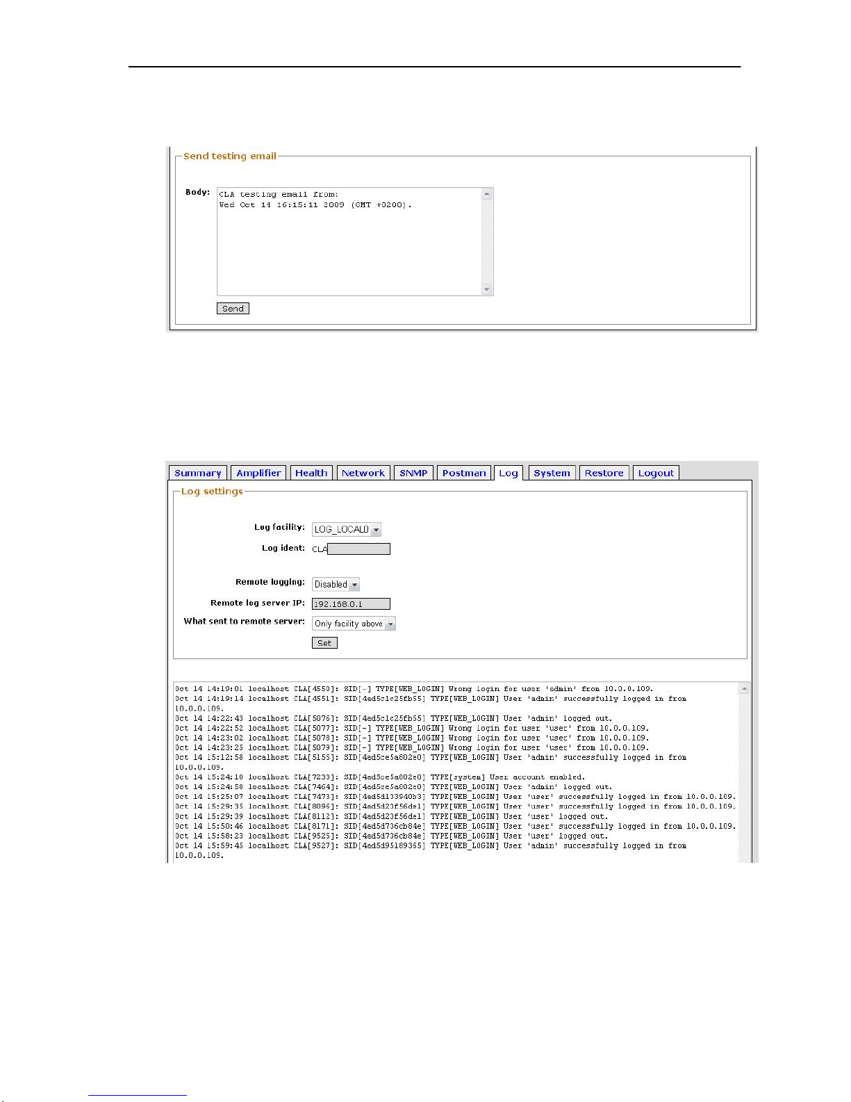
After setting Postman properties can send “Testing email” and verify Postman
function. To email body can write your text.
Picture 18 - Postman testing mail
10.9 Log
This component part is available by admin account only.
This component part allows Log record system settings and read login records.
Picture 19 – Log
Page 37
EDFA optical amplifier – user manual
37
10.10 System
This component part is available by admin account only.
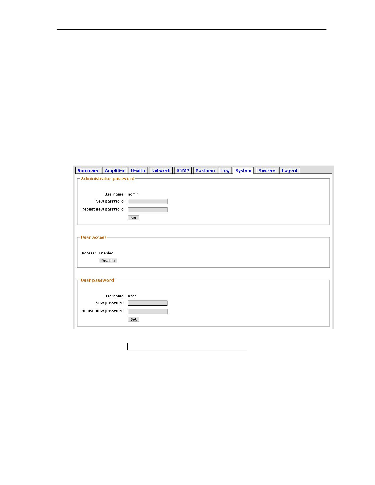
The component part System allows change following properties
Admin and User password
Basic device information
Date and Time
Web interface secure properties
Account properties
Only Administrator can change Administrator`s and User`s passwords. In this
part can enable or disable User account also.
Picture 20 - System – accounts
Access
Enable or disable User account
Table 12 - System accounts
Page 38
EDFA optical amplifier – user manual
38
Base device information
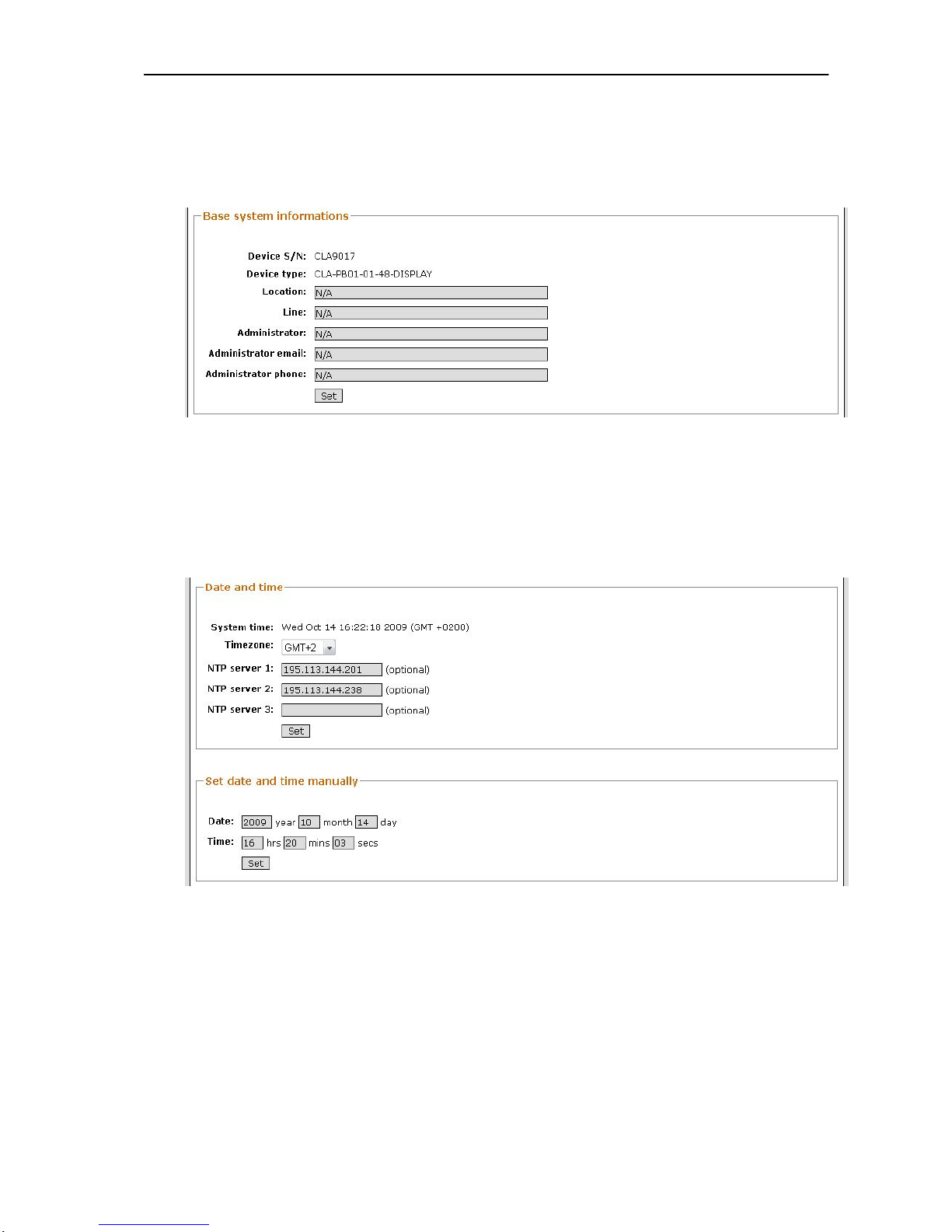
In this part are placed basic information about the device. These information are
displayed by login to the device.
Picture 21 - System - Device information
All items are descript in Table 1, chapter 9.2
Date and Time
In this part can choose source of Date and Time – timeserver or manually
settings.
Picture 22 - System - Date & Time
Page 39
EDFA optical amplifier – user manual
39
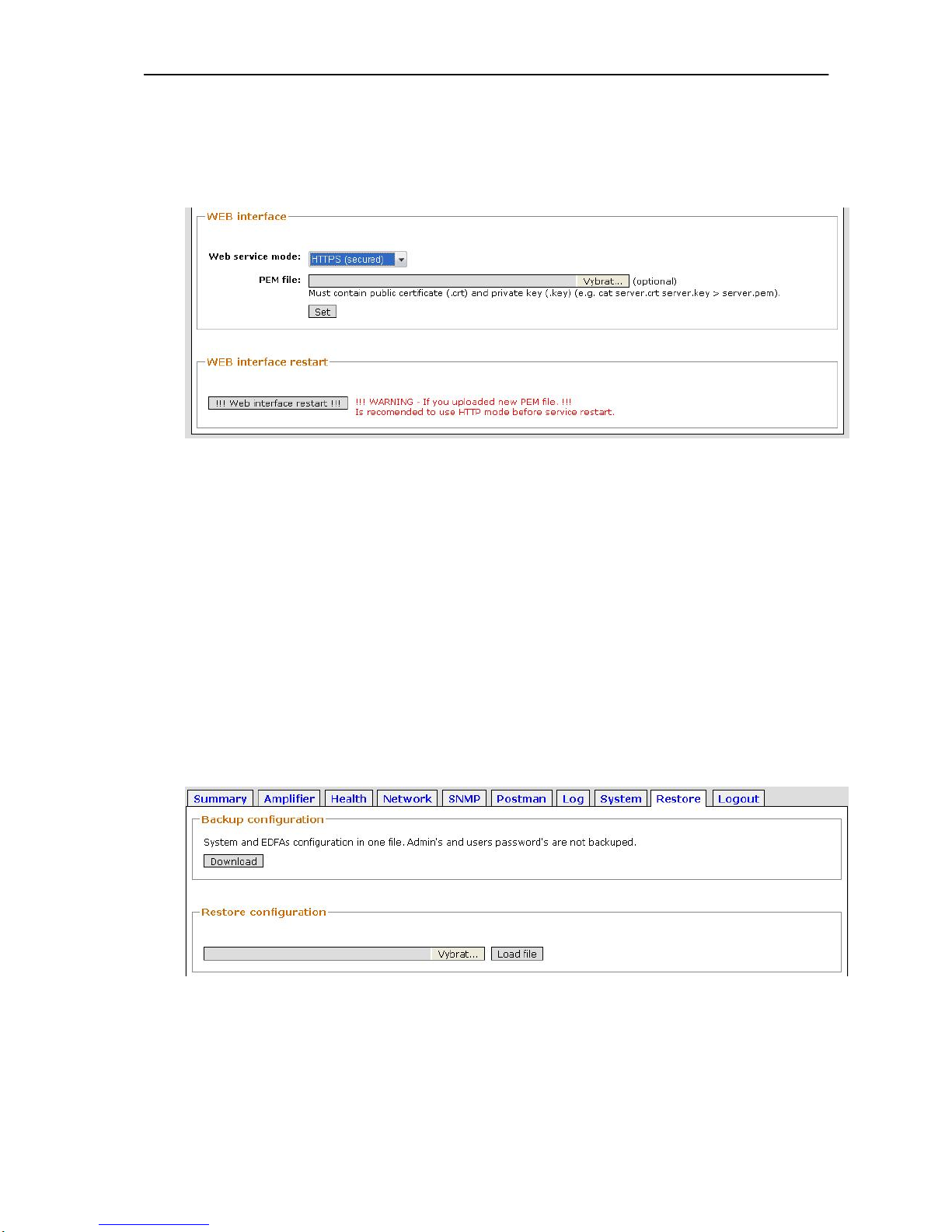
Web interface secure
This part allows chose web service mode HTTPS or HTTP and choose your
certificate (public or private) for HTTPS service.
Picture 23 - System - Web interface secure
NOTICE: for accept your changes click to button “Web interface restart”.
WARNING: Is recommended to use HTTP mode before service restart!
10.11 Restore
This component part is available by admin account only.
Restore component part is in service for setting the device and its components
to default status or for backup settings
Backup and Restore configuration
Administrator can store device configuration to one file and conversely can
same file use for loading of backup device configuration.
Picture 24 – Restore, Backup configuration
Page 40
EDFA optical amplifier – user manual
40
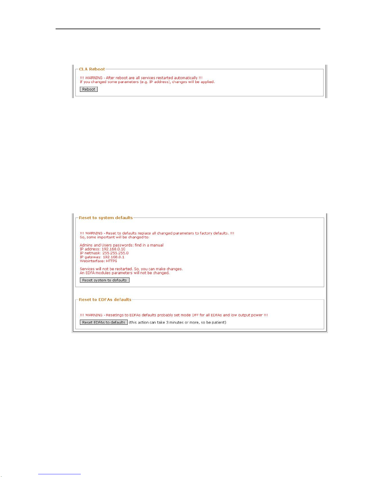
CLA Reboot
Reboot service provides restart of PC motherboard.
Picture 25 - Restore - CLA reboot
NOTICE: this procedure can take about 3 minutes.
WARNING: If you changed some parameters (e.g. IP address or Firewall etc),
your changes will be applied after restart.
Load default settings and restart
This procedure can be separate to two groups:
Load default settings of the DEVICE and restart
o EDFA unit settings will not be changed.
Load default settings of the EDFA unit and restart
o DEVICE settings will not be changed.
Picture 26 - Restore - System and EDFA defaults
NOTICE: Each restart procedure can take about 3 minutes. Same as CLA
reboot.
WARNING: Resetting to default setting probably set EDFA unit to OFF mode!
Page 41
EDFA optical amplifier – user manual
41
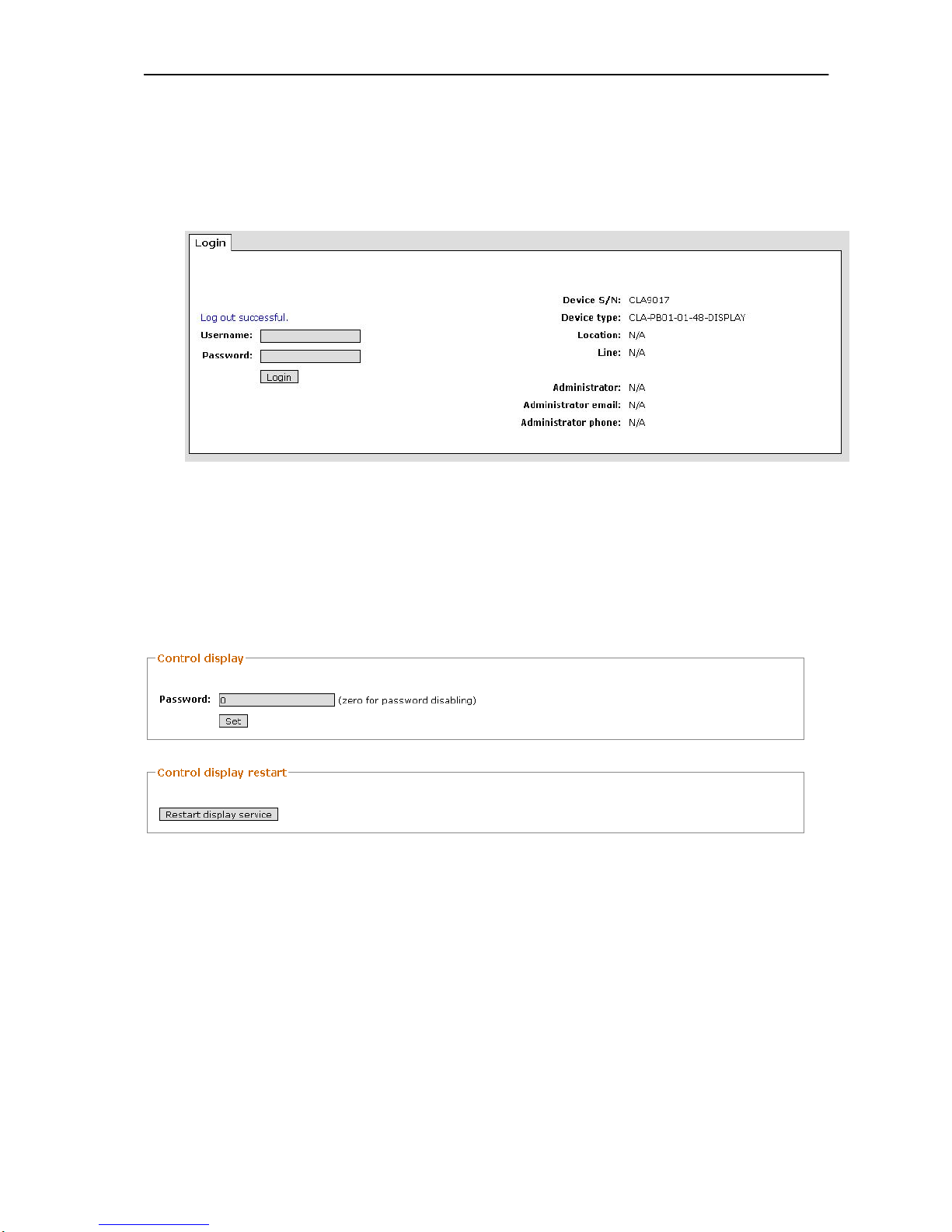
10.12 Logout
Please, provide correct logout from CLA web interface after ending your work.
The Web interface is switched after correct logout procedure to login window and
reply by web interface is “Log out successful”
Picture 27 – Logout
10.13 Display password (optionally)
In the item SYSTEM is available change of display password. After your
change you must click to Restart display service.
If the display password is 0 (zero), the password function is doesn`t function
on the display module.
Page 42

EDFA optical amplifier – user manual
42
11 Display
Main menu
The Main menu contains basic items according this screenshot. The user can
choose each item via buttons UP/DOWN. For enter to item use the middle button
(character “O”)
Ma i n me n u
Over vi ew
He a l t h
Al a r ms
Parameters
Settings
Scr eensaver
Hel p and About
Main menu -> Overview
Overview menu contains only report about the basic EDFA status.
EDFA 1
MODE : 0
TEMPER : 25.2C
EDFA 1 S1 - Pr eamp 16dB
AGC : 20.00dB
APC : 15.00dBm
POWER_I N : - 50. 00dBm
POWER_OUT: - 50. 00dBm
EDFA 1 means the first EDFA module inside the CLA
EDFA 2 means the second EDFA module inside the CLA
EDFA 1 S1 means the first stage in EDFA 1 (Pre-amp or Booster)
EDFA 1 S2 means the second stage in EDFA 1 (Pre-amp or Booster)
Example:
CLA PB01F
EDFA 1 S1 – Pre-amplifier
EDFA 1 S2 – Booster amplifier
CLA PB02F
EDFA 1 S1 – Pre-amplifier
EDFA 2 S1 – Booster amplifier
Main menu -> Health
Item Health contains same information as in Bios of PC (Voltage status on the
power supply units, temperatures, fan speed)
Page 43

EDFA optical amplifier – user manual
43
Vol t ages
VOLT_R05V: 5. 05V
VOLT_R12V: 11. 98V
VOLT_L05V: 5. 02V
VOLT_L12V: 11. 98V
Temper at ur es
TEMP_CHI P: 29. 00C
Fan r ounds
VOLT_L12V: 11. 98V
Temper at ur es
TEMP_CHI P: 29. 00C
Fan r ounds
FAN_FAN1 : 6452RPM
FAN_FAN2 : 6683RPM
FAM_FAN3 : 4415RPM
FAN_FAN4 : 0RPM
Main menu -> Alarms
Item Alarms contains report about alerts on the EDFA units. Alarms see in
chapter 13.
Al e r t s
EDFA 1 S1 - Pr eamp 16dB
INLOS
OUT L OS
EDFA 1 S2 - Boost er 20dB
INLOS
OUT L OS
If don`t exist alarms, the display screen information “No alarms found”.
No al ar ms f ound.
Main menu -> Parameters
Item Parameters enable see technical and optical parameters of the EDFA units.
Page 44

EDFA optical amplifier – user manual
44
Vi ew st at us
EDFA 1
EDFA 1 S1 - Pr eamp 16dB
EDFA 1 S2 - Boost er 20dB
Main menu -> Parameters -> EDFA 1
The item contains basic information about the EDFA unit. User can listed via
buttons UP/DOWN.
Vi e w EDFA 1
VENDOR : Manl i ght
MODULE : 2i n1 EDFA
HWVER : 2
HWREV : A
SWVER : 2.05
Vi e w EDFA 1
FWVER : NA
SERNUM : 8811881188
CATNUM : 1000001234
PRODDATE : 05/ 17/ 10
MODE : 0
TEMPER : 25.8C
VENDOR - vendor
MODULE - model of the EDFA unit
HWVER - hardware version
HWREV - revision of hardware version
SWVER - software version
FWVER - firmware version
SERNUM - serial number of the EDFA unit
CATNUM - product number of the EDFA unit
PRODDATE - date of production
MODE - actual working mode (OFF, APC, AGC, ACC)
TEMPER - temperature inside case of the EDFA unit
Main menu -> Parameters -> EDFA 1 S1
The item contains report about electrical and optical parameters. User can listed
via buttons UP/DOWN.
Page 45

EDFA optical amplifier – user manual
45
Vi ew EDFA 1 - st age 1
ACC : 0.0mA
AGC : 20.0dB
ALSFNC : E
ALSVAL : -10.0dBm
APC : 15.0dBm¨
GAIN : -27.0dB
Vi ew EDFA 1 - st age 1
TEC_ 1 _ CURRENT : 2 5 . 3 mA
LD_1_CURRENT : 0. 6mA
LI : -30.0dBm
LO : -10.0dBm
PLD_ 1_ POWER : 0mW
PDL_1_TEMP : 24.9C
Vi ew EDFA 1 - st age 1
POWER_IN : -50.0dBm
POWER_OUT : -50.0dBm
POWER_MAX : 16.0dBm
GAIN_MAX : 35.0dB
CURRENT_MAX : 280. 0mA
Items are described in Chapter 9.4 - Table 8.
Main menu -> Settings
Item Settings enables change of the EDFA optical parameters, Network
parameters and change of display password.
Settings menu
EDFA settings
Net wor k set t i ngs
Set di spl ay passwor d
Main menu -> Settings -> EDFA settings
This item enables change of the EDFA optical parameters.
Page 46

EDFA optical amplifier – user manual
46
EDFA s e t t i n gs
EDFA 1
EDFA 1 S1 - Pr eamp 16dB
EDFA 1 S2 - Boost er 20dB
Change t o exper t mode
Main menu -> Settings -> EDFA settings -> EDFA 1
User can set actual the EDFA working mode.
Setting EDFA 1
MODE
Oper at i on mode of EDFA modul e
OF F
APC ( Aut omat i c power cont r ol )
AGC ( Aut omat i c gai n cont r ol )
The ACC mode is via the Display module denied.
The information about working mode in Chapter 12 - Table 13
Main menu -> Settings -> EDFA settings -> EDFA 1 S1 (Standard mode)
User can change settings of working mode and threshold for Loss IN or OUT alarm.
Set t i ng EDFA 1 - st age 1
APC
AGC
LI
LO
For editing the values use the Display module keyboard.
For changing of the position use buttons LEFT/FIGHT
For character browsing use buttons UP/DOWN
Page 47

EDFA optical amplifier – user manual
47
For confirm of your changes use the middle button
Example:
Type i n AGC i n dB:
20.
Gai n val ue set i n AGC mode
0
Main menu -> Settings -> EDFA settings -> Expert / Standard mode
This item enables change of level settings for the EDFA unit. The standard
mode enables only basic settings. The expert mode enables settings all available
parameters.
Example by EDFA 1 S1 (Expert mode):
Set t i ng EDFA 1 - st age 1
ACC
AGC
ALSFNC
ALSVAL
APC
Set t i ng EDFA 1 - st age 1
LI
LO
POWER_MAX
GAI N_ MAX
CURRENT _ MAX
Main menu -> Settings -> Network settings
In this part user can change of Network settings.
Net wor k set t i ngs
I P addr ess
Net wor k mask
Default gateway
Rest ar t net wor ki ng
I CMP pi ng
For editing the values use the Display module keyboard.
Page 48

EDFA optical amplifier – user manual
48
For changing of the position use buttons LEFT/FIGHT
For character browsing use buttons UP/DOWN
After user changing of network adaptor must be restarted the network adaptor.
Net wor k r est ar t :
Net wor ki ng was r est ar t ed!
Now click to back button.
Main menu -> Settings -> Network settings -> Set display password
The settings of the CLA and EDFA unit can be protected via display password.
If you need protect your CLA settings set the password with four digits. The
password can contain only numbers.
If you need turn display password off, set the password “0” (zero).
If you forgot your password, you can turn display password off via web
interface see in Chapter 9.13.
Type i n a new passwor d:
0
Main menu -> Screensaver
This choose turn Screensaver on. The screensaver is started after about one
minute from last pressing of button.
Main menu -> Help and About
This item contains the main help and short information about version of FW
display and about creators.
The GAME
If you want to shorten the time during waiting, you can play a small game on
the display module.
Choose Main menu -> Help and About, press quick help button and run.
Page 49

EDFA optical amplifier – user manual
49
12 Detailed EDFA Command set
ACC{sp}[1,2]{sp}<value>{cr} Set Pump Currents in mA in ACC mode
Set the pump currents in mA in ACC mode.
Example usage:
ACC{sp}1{sp}200{cr}
Reply is:
ACC{sp}1{sp}200.0{cr}
the laser 1 is supplied at 200 mA.
ACC{sp}[1,2,A]{cr} Report Pump Currents in mA in ACC mode
Report the pump currents in mA in ACC mode.
Example usage:
ACC{sp}1{cr}
Reply is:
LASER1:{sp}200.0{sp}mA{cr}
the laser 1 current is 200 mA.
Example usage:
ACC{sp}A{cr}
Reply is:
ALL:{sp}200.0{sp}700.0{cr}
AGC{cr} Report the gain set in AGC mode.
Example usage:
AGC{cr}
Reply is:
AGC{sp}1:{sp}30{sp}dB{cr}
AGC{sp}2:{sp}17{sp}dB{cr}
Page 50

EDFA optical amplifier – user manual
50
AGC{sp}[1,2]{sp}<value>{cr} Set the gain in AGC OADM mode for each stage.
Example usage:
AGC{sp}1{sp}18{cr}
Reply is:
AGC{sp}1{sp}18{cr}
the gain for stage 1 in AGC OADM mode is set to 18 dB.
ALS{sp}[1,2]{sp} [E;D] {cr} Set the automatic laser shutdown function.
Set the automatic laser shutdown function to enable or disable when the loss of input alarm .
Set the output power value for each stage when the loss of input alarm or OPMI is activated.
Example usage:
ALS{sp}1{sp}E{cr}
Reply is:
ALS{sp}1{sp}E{cr}
set the automatic laser shutdown function for stage 1 to enable. If the input power goes below the
Loss of input value, the electronic will shutdown the laser diodes and then the output power will
be less than 0 dBm
Example usage:
ALS{sp}2{sp}D{cr}
Reply is:
ALS{sp}2{sp}D{cr}
set the automatic laser shutdown function for stage 2 to disable. If the input power stage 2 goes
below the Loss of input value stage 2, the output power stage 2 will stay at its previous value.
ALS {sp}[1,2]{cr} Report the automatic laser shutdown function.
Example usage:
ALS{sp}1{cr}
Reply is:
ALS{sp}1:{sp}ENABLE{cr}
Report the automatic laser shutdown function for stage 1 is enable.
Example usage:
ALS{sp}2{cr}
Reply is:
ALS{sp}2:{sp}DISABLE{cr}
Page 51

EDFA optical amplifier – user manual
51
Report the automatic laser shutdown function for stage 2 is disable.
AM{sp}[O,C,P,G]{cr} Change the operation mode.
Change the operation mode of the EDFA between the 4 modes : ACC, APC, AGC, OFF.
Example usage:
AM{sp}O{cr}
Change the operation of the EDFA module to off mode. In OFF mode, the
laser diode driving current are set to 0 mA, alarms are disabled, and TEC are
enabled.
Reply is:
AM{sp}O{cr}
AM{sp}C{cr}
Change the operation of the EDFA module to current constant mode (ACC
mode).
Reply is:
AM{sp}C{cr}
AM{sp}P{cr}
Change the operation of the EDFA module to output power constant mode
(APC mode).
Reply is:
AM{sp}P{cr}
AM{sp}G{cr}
Change the operation of the EDFA module to constant gain mode (AGC
mode).
Reply is:
AM{sp}G{cr}
Page 52

EDFA optical amplifier – user manual
52
AM{cr} Reports the EDFA Mode.
Example usage:
AM{cr}
Reply is:
AM:{sp}O{cr}
EDFA operates in OFF mode. In OFF mode, the laser diode driving current
are set to 0 mA, alarms are disabled, and TEC are enabled.
or Reply is:
AM:{sp}G{cr}
EDFA operates in AGC mode.
or Reply is:
AM:{sp}C{cr}
EDFA operates in ACC mode.
APC{sp}[1,2]{sp}<value>{cr} Set the output power in APC mode for each stage.
Example usage:
APC{sp}1{sp}11{cr}
Reply is:
APC{sp}1{sp}11{cr}
the output power for stage 1 in APC mode is set to 11 dBm.
APC{cr} Report the output power in APC mode for each stage.
Example usage:
APC{cr}
Reply is:
APC{sp}1:{sp}10 dBm{cr}
APC{sp}2:{sp}17 dBm{cr}
the output power for stage 1 in APC mode is set to 10 dBm, the output power
for stage 2 in APC mode is set to 17 dBm.
Page 53

EDFA optical amplifier – user manual
53
AS{cr} EDFA Module Status Request
Reports any problems with the EDFA module:
Reply is:
STATUS:{sp}ADI{sp}OPMI{sp}PTMP{sp}PI{cr}
GA{sp}[1,2]{cr} Reports Amplifier Gain in dB for each stage (ASEcorrected)
Example usage:
GA{sp}1{cr}
Reply is:
GAIN STAGE 1:{sp}18{sp}dB{cr}
The amplifier gain stage 1 is 18 dB.
In AGC OADM mode, GA 1 value should the same as AGC 1 set value, and
GA 2 value should the same as AGC 2 set value.
Indicator Parameters Description
STAGE 1 IN LOS
STAGE 2 IN LOS
Loss of input signal alarm
stage 1 and stage 2
The loss of input power will send an
alarm on the RS232 port when
sending alarm status command and on
the electric connector (TTL signal).
The value of the input power alarm
threshold is settable and may be
disabled.
STAGE 1 OUT LOS
STAGE 2 OUT LOS
Loss of output signal alarm
stage 1 and stage 2
The loss of output power will send an
alarm on the RS232 port (when
sending alarm status command), and
on the electric connector (TTL signal).
This feature may announce a possible
EDFA problem. The value of the loss
of output power alarm threshold is
settable and may be disabled.
TINT Internal Temperature Alarm TINT indicates that the EDFAs internal
case temperature is out of limits.
PTMP Pump temperature alarm This feature sends an alarm if one or
several laser diode exceed the set
value by 2° C.
PUMP BIAS Pump bias current alarm This feature sends an alarm if one or
several laser diode currents exceed 95
% of end of life current.
ADI Disable Alarm ADI indicates that the disable electrical
input pin is active. In DI state, the laser
diode power supply is turned off by a
transistor. The TEC power supply stay
turned on.
OPMI Eye-safe Power Control Input
(mute)
When active, the output power for
each stage is set to mute power (ALS
values)
Page 54

EDFA optical amplifier – user manual
54
HA{sp}[1,2,A]{cr} Report TEC currents.
Example usage:
HA{sp}1{cr}
Reply is in the form:
LASER1:{sp}500{sp}mA{cr}
Signifying that the TEC 1 consumes 500 mA.
Example usage:
HA{sp}A{cr}
Reply is in the form:
ALL:{sp}500{sp}2000{sp}mA{cr}
Signifying that the TEC 1 consumes 1000 mA, TEC 2 consumes 2000 mA
IT{cr} Get Internal temperature (case temperature)
Example usage:
IT{cr}
Reply is in the form:
TINT:{sp}30.3{sp}C{cr}
The range for the internal case temperature is : 2.0 C – 65.0 C.
LC{sp}[1,2,A]{cr} Get Pump Laser Diode Drive Current
Example usage:
LC{sp}1{cr}
Reports pump laser drive current for pump laser diode 1.
Reply is:
LASER1:{sp}280.4{sp}mA{cr}
If the requested pump laser diode is not fitted into the EDFA module, then the
reply is:
FWC{cr}
Example usage (for all lasers):
LC{sp}A{cr}
Reports pump laser drive current for all lasers.
Reply is:
ALL:{sp}280.4{sp}521.6{sp}mA{cr}
Page 55

EDFA optical amplifier – user manual
55
LI{sp}[1,2]{sp}<value>{cr} Set Loss of Input power Signal alarm
threshold for each stage
Set the Loss of input power Signal alarm threshold. Note that a LI event on a stage should mute
the output power stage only if ALS is enabled..
Example usage:
LI{sp}1{sp}-25{cr}
Set LI alarm threshold stage 1 to -25.0 dBm
Reply is:
LI{sp}1{sp}-25{cr}
Example usage:
LI{sp}2{sp}-20{cr}
Set LI alarm threshold stage 2 to -20.0 dBm
Reply is:
LI{sp}2{sp}-20{cr}
LI{cr} Get Loss of Input Power Signal alarm threshold for each stage
Example usage:
LI{cr}
Get the value of the Loss of Input power Signal alarm threshold for
Reply is:
LI{sp}1:{sp}-20.0{sp}dBm{cr}
LI{sp}2:{sp}0.0{sp}dBm{cr}
Indicating that LI stage 1 =-20 dBm and LI stage 2 =0 dBm
LO{sp}[1,2]{sp}<value>{cr} Set Loss of Output power Signal alarm
threshold for each stage
Set the Loss of output power Signal alarm threshold. Note that a LO event should not disable the
EDFA.
Page 56

EDFA optical amplifier – user manual
56
Example usage:
LO{sp}1{sp}10{cr}
Set LO alarm threshold stage 1 to 10 dBm
Reply is:
LO{sp}1{sp}10{cr}
Example usage:
LO{sp}2{sp}20{cr}
Set LO alarm threshold stage 2 to 20.0 dBm
Reply is:
LO{sp}2{sp}20{cr}
LO{cr} Get Loss of Output Power Signal alarm threshold for each stage
Example usage:
LO{cr}
Get the value of the Loss of Output Power Signal alarm threshold.
Reply is:
LO{sp}1:{sp}10.0{sp}dBm{cr}
LO{sp}2:{sp}20.0{sp}dBm{cr}
Indicating that LO stage 1 =10 dBm and LO stage 2 =20 dBm
LP{sp}[1,2,A]{cr} Get Pump Laser Output Power
Example usage:
LP{sp}1{cr}
Reports pump laser output power for pump laser diode 1.
Reply is:
LASER1:{sp}180.4{sp}mW{cr}
If the requested pump laser diode is not fitted into the EDFA module, then the
reply is:
FWC{cr}
LP{sp}A{cr}
Reports pump laser output power for all pump lasers.
Reply is:
ALL:{sp}100.5{sp}120.5{sp}mW{cr}
Page 57

EDFA optical amplifier – user manual
57
LT{sp}[1,2,A]{cr} Get TEC Temperature
Example usage:
LT{sp}1{cr}
Requests TEC temperature of pump laser 1
Reply is in the form:
LASER1:{sp}25.5{sp}C{cr}
Signifying that the pump laser 1 has a temperature of 25.5 C.
Example usage:
LT{sp}A{cr}
Requests TEC temperature of all pump laser.
Reply is in the form:
ALL:{sp}25.2{sp}25.0{sp}C{cr}
The range for the TEC temperature is: 15.0 C to 35.0 C.
PH{cr} Get the Optical Powers in the EDFA Module
Example Usage:
PH{cr}
Reply is in the form shown, where PDM1 is the input power stage 1, PDM2 is
the output power stage 1 before the VOA, PDM3 is the input power stage 2,
PDM4 is the output power stage 2.
PDM1:{sp}-8.2{sp}dBm{cr}
PDM2:{sp}10.0{sp}dBm{cr}
PDM3:{sp}6.4{sp}dBm{cr}
PDM4:{sp}20.5{sp}dBm{cr}
TS{sp}[1,2]{sp}<value>{cr} Set TEC Temperature.
This command is used to set the TEC. The TEC temperature has a fixed value internally (say
25 C).
Example usage:
TS{sp}1{sp}25{cr}
Sets the operating set point to 25 C.
Reply is in the form:
TS{sp}1{sp}25{cr}
The TEC temperature has a settable value. An error will be generated if the
settable value is below the minimum temperature and if the settable value is
above the maximum temperature. Available on prototypes and series.
The range for the TEC temperature is: 15.0 C to 35.0 C.
Page 58

EDFA optical amplifier – user manual
58
TS{sp}[1,2,A]{cr} Get TEC Temperature.
Example usage:
TS{sp}1{cr}
Reports the minimum submount temperature, the operating set point, and the
maximum submount temperature of laser diode 1.
Reply is in the form:
LASER1:{sp}25.0{sp}C{cr}
Signifying that the laser 1 has a submount temperature of 25 C.
Example usage:
TS{sp}A{cr}
Reports the operating set point temperature of all laser diodes.
Reply is in the form:
ALL:{sp}25.0{sp}25.0{sp}C{cr}
The range for the TEC temperature is: 15.0 C to 35.0 C.
V{cr} Vendor/Device
Get the vendor/device and the software release version. The answer is in the form : vendor (8
digits), vendor’s module name, amplifier version, Hardware version, software version, firmware
version, serial number (10 digits), vendor’s part number (11 digits), module serial number (10
digits), date of production (DD/MM/YYYY)
Example usage :
V{cr}
Reply is in the form:
Vendor{sp}={sp}HIGHWAVE{cr}
Module{sp}={sp}2in1{sp}EDFA{cr}
AW{sp}Ver{sp}={sp}1{cr}
HW{sp}Rev{sp}={sp}A{cr}
SW{sp}Ver{sp}={sp}1.01{cr}
FW{sp}Ver{sp}={sp}1.01{cr}
Ser{sp}Num{sp}={sp}1010350001{cr}
Cat{sp}Num{sp}={sp}1*4922{cr}
Prod{sp}Date{sp}={sp}12/12/2003{cr}
Page 59
EDFA optical amplifier – user manual
59
13 EDFA education and Application note
If you never work with optical amplifier and especially with EDFA optical
amplifier, please, read this chapter before using.
13.1 EDFA education
You get knowledge in this chapter some basic information about EDFA system
of amplification, what`s mean under term “EDFA” and basic EDFA block scheme
and its function.
What`s mean under term “EDFA”
EDFA is acronym for Erbium Doped Fiber Amplifier. This principle don`t need
convert the optical signal to the electric signal. The amplification is provided in the
special optical fiber which is doped by Erbium element. The Erbium doped fiber is
used as gain medium. The optical signal comes into Erbium Doped Fiber together
and is mixed with next energy in form pump signal and input signal is amplified
trough interaction with the doping ions. Erbium element is used because Erbium
ions can be efficiently pumped with a laser at wavelength 980nm or 1480. The
Gain is in 1550nm wavelength region.
EDFA optical amplifier can be used for amplification at C-Band only!
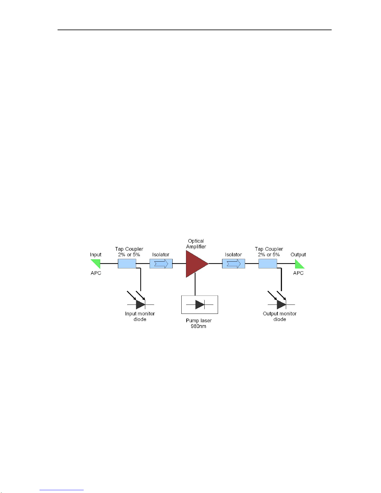
EDFA block scheme
Picture 28 - EDFA block scheme
APC connector are using by all EDFA optical amplifier. The output optical level
is often very high and high optical level can damage connector with help effect of
back reflection.
Each EDFA involves isolator for protection against reverse connection
Each Inputs and Outputs are monitored by monitor diodes for better settings of
optical properties and for feedback control electronic.
Various EDFA units can involve more than one pump laser diodes. By these
pump diodes are measured values like current, temperature, current temperature
control etc. These measured values are same as values from monitor diodes
connect to control electronic for control operational modes APC and AGC.
Page 60

EDFA optical amplifier – user manual
60
EDFA Operational modes
Each EDFA unit can work in four operational modes. These modes were
created for independent work of optical amplifier on the optical trace. User have to
set properties of each operational mode only and control electronic control gain or
output power according to user`s settings.
EDFA unit can work in the following four operational modes:
Operational mode Description
OFF
Pump diodes are shutdown.
The EDFA unit don`t amplify
APC
Amplifier Power Control
User set constant output optical level
AGC
Amplifier Gain Control
User set constant gain
ACC
Amplifier Current Control
User set constant
Table 13 - EDFA operational modes
Operational mode settings example
Example 1
Conditions:
Pin = -5 dBm AGC = 15 dB
Results:
Pout = +10 dBm
Example 2
Conditions:
Pin = -10 dBm AGC = 15 dB
Result:
Pout = +5 dBm
Example 3
Conditions:
Pin = -5 dBm APC = 15 dB
Result:
Pout = +15 dBm
Example 4
Conditions:
Pin = -10 dBm APC = 15 dB
Result:
Pout = +15 dBm
Page 61
EDFA optical amplifier – user manual
61
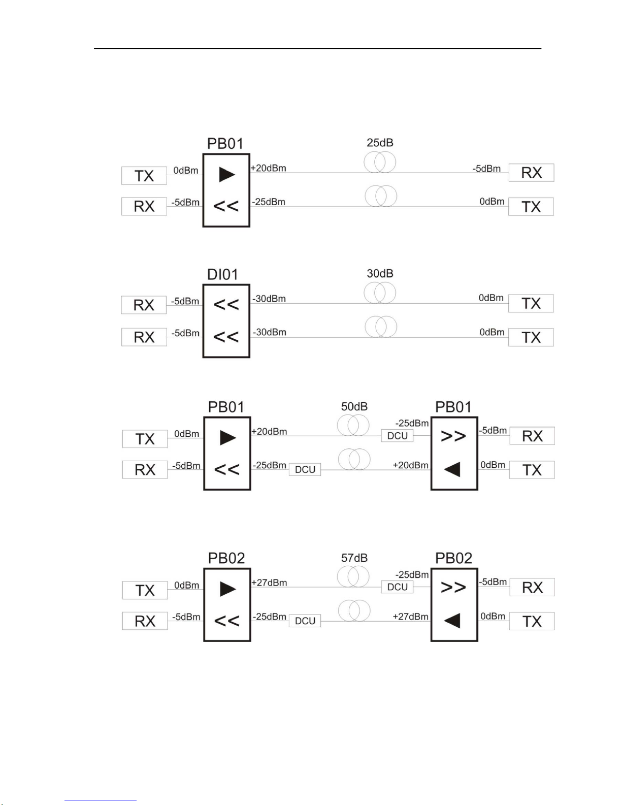
13.2 Application note
This chapter shows some examples connection and using some models of
OPTOKON Amplifiers.
Picture 29 - Application note
Note: “►” Booster Amplifier
“>>” Pre-Amplifier
PBxx – Pre-Amplifier and Booster
DIxx – Dual Inline Amplifier
DCU – Dispersion Compensation Unit
Page 62

EDFA optical amplifier – user manual
62
14 Alarms
Name Full name Description
TINT Internal temperature alarm Indicate that the EDFA`s internal
case temperature is out of limits
MODULE_SHUT_TEMP Module automatically shutdown
alarm
The alarm is activated if any single
pump laser diode temperatures
exceed the set value by 2 Celsius
and control electronic automatically
shutdown pump laser diodes.
PTMP Pump temperature alarm The alarm is activated if any single
pump laser temperature is higher
than the software maximum alarm
or less than the software minimum
alarm.
EOL End of life of pump diode alarm The alarm is activated if any single
pump laser current reaches 95% of
its End Off Life value.
The values are noted in “Active
Report Unit” document.
ADI Amplifier Disable alarm The signal present that that the
laser pump diodes power supply is
turned off. The amplifier don`t
amplify now.
The Temperature control power
supply stay turned on.
OPMI Eye-safe Power Control alarm When active, the output power is
set to mute power according to ALS
function. (default 0dBm)
PUMPON Pump diode ON This signal isn`t alarm. This signal
only report that Laser Pump diodes
are active and optical amplifier
amplify input signal.
INLOSS Loss of input alarm The input signal is lower than loss
of input alarm threshold. Alarm
threshold is settable and may be
disabled (set LI to -50.00dBm)
OUTLOSS Loss of output alarm The output signal is lower than loss
of output alarm threshold. Alarm
threshold is settable and may be
disabled (set L0 to -50.00dBm)
Table 14 - Alarms
Page 63

EDFA optical amplifier – user manual
63
15 Contacts:
OPTOKON, a.s.
Červený Kříž 250,
Jihlava,586 02
Czech Republic
OPTOKON, a.s.
Prague office
Venušina 1149/3
104 00, Praha 10
Czech Republic
Phone: +420 602 421 029
E-mail: [email protected]
Internet: WWW.OPTOKON.COM
 Loading...