

opto engineering COE HR AS-X, COE-260, COE-290 User Manual
COE-260 & COE-290
GigE Camera
USER MANUAL
V1.0
CAMERAS
COE HR AS-X series

1
User Manual
About this Manual
This Manual is applicable to COE HR AS-X series GigE cameras.
The Manual includes instructions for using and managing the product. Pictures, charts, images and all other information
hereinafter are for description and explanation only. The information contained in the Manual is subject to change, without
notice, due to firmware updates or other reasons. Please find the latest version in the company website.
Please use this user manual under the guidance of professionals.
Legal Disclaimer
TO THE MAXIMUM EXTENT PERMITTED BY APPLICABLE LAW, THE PRODUCT DESCRIBED, WITH ITS HARDWARE,
SOFTWARE AND FIRMWARE, IS PROVIDED "AS IS", WITH ALL FAULTS AND ERRORS, AND OUR COMPANY MAKES NO
WARRANTIES, EXPRESS OR IMPLIED, INCLUDING WITHOUT LIMITATION, MERCHANTABILITY, SATISFACTORY
QUALITY, FITNESS FOR A PARTICULAR PURPOSE, AND NON-INFRINGEMENT OF THIRD PARTY. IN NO EVENT WILL
OUR COMPANY, ITS DIRECTORS, OFFICERS, EMPLOYEES, OR AGENTS BE LIABLE TO YOU FOR ANY SPECIAL,
CONSEQUENTIAL, INCIDENTAL, OR INDIRECT DAMAGES, INCLUDING, AMONG OTHERS, DAMAGES FOR LOSS OF
BUSINESS PROFITS, BUSINESS INTERRUPTION, OR LOSS OF DATA OR DOCUMENTATION, IN CONNECTION WITH THE
USE OF THIS PRODUCT, EVEN IF OUR COMPANY HAS BEEN ADVISED OF THE POSSIBILITY OF SUCH DAMAGES.
REGARDING TO THE PRODUCT WITH INTERNET ACCESS, THE USE OF PRODUCT SHALL BE WHOLLY AT YOUR OWN
RISKS. OUR COMPANY SHALL NOT TAKE ANY RESPONSIBILITIES FOR ABNORMAL OPERATION, PRIVACY LEAKAGE
OR OTHER DAMAGES RESULTING FROM CYBER ATTACK, HACKER ATTACK, VIRUS INSPECTION, OR OTHER INTERNET
SECURITY RISKS; HOWEVER, OUR COMPANY WILL PROVIDE TIMELY TECHNICAL SUPPORT IF REQUIRED.
SURVEILLANCE LAWS VARY BY JURISDICTION. PLEASE CHECK ALL RELEVANT LAWS IN YOUR JURISDICTION BEFORE
USING THIS PRODUCT IN ORDER TO ENSURE THAT YOUR USE CONFORMS THE APPLICABLE LAW. OUR COMPANY
SHALL NOT BE LIABLE IN THE EVENT THAT THIS PRODUCT IS USED WITH ILLEGITIMATE PURPOSES.
IN THE EVENT OF ANY CONFLICTS BETWEEN THIS MANUAL AND THE APPLICABLE LAW, THE LATER PREVAILS.
Warning
This is a class A product. In a domestic environment this product may cause radio interference in which case the user may be
required to take adequate measures.
Safety Instruction
These instructions are intended to ensure that the user can use the product correctly to avoid danger or property loss.
The precaution measure is divided into ‘Warnings’ and ‘Cautions’:
Warnings: Serious injury or death may be caused if any of these warnings are neglected.
Cautions: Injury or equipment damage may be caused if any of these cautions are neglected.
Warnings Follow these safeguards to prevent
serious injury or death.
Cautions Follow these precautions to prevent
potential injury or material damage.
Warnings:
Please adopt the power adapter which can meet the safety extra low voltage (SELV) standard. And source with 12 VDC
(depending on models) according to the IEC60950-1 and Limited Power Source standard.
To reduce the risk of fire or electrical shock, do not expose this product to rain or moisture.
This installation should be made by a qualified service person and should conform to all the local codes.
Please install blackouts equipment into the power supply circuit for convenient supply interruption.
Please make sure that the ceiling can support more than 50(N) Newton gravities if the camera is fixed to the ceiling.

2
If the product does not work properly, please contact your dealer or the nearest service center. Never attempt to
disassemble the camera yourself. (We shall not assume any responsibility for problems caused by unauthorized repair or
maintenance.)
Cautions:
Make sure the power supply voltage is correct before using the camera.
Do not drop the camera or subject it to physical shock.
Do not touch sensor modules with fingers. If cleaning is necessary, use a clean cloth with a bit of ethanol and wipe it
gently. If the camera will not be used for an extended period of time, put on the lens cap to protect the sensor from dirt.
Do not aim the camera lens at the strong light such as sun or incandescent lamp. The strong light can cause fatal damage
to the camera.
The sensor may be burned out by a laser beam, so when any laser equipment is being used, make sure that the surface of
the sensor not be exposed to the laser beam.
Do not place the camera in extremely hot, cold temperatures (the operating temperature should be between -0°C to
50°C), dusty or damp environment, and do not expose it to high electromagnetic radiation.
To avoid heat accumulation, ensure there is good ventilation to the device.
Keep the camera away from water and any liquids.
While shipping, pack the camera in its original, or equivalent, packing materials. Or packing the same texture.
Improper use or replacement of the battery may result in hazard of explosion. Please use the manufacturer
recommended battery type.

3
Part Number
Part number
Description
COE-260-M-10GIGE-100-IR
CMOS, Python 25K, APS−H, 5120x5120, 4.5pix, F mount, M58x0.75 FD11.48
COE-290-x-GIGE-110-yy-B
CCD, KAI-29050, 35mm, 6576x4384, 4.5pix,F mount, M58x0.75 FD11.48, GIGE
COE-290-M-GIGE-110-IR-A
CCD, KAI-29050, 35mm, 6576x4384, 4.5pix,F mount, M58x0.75 FD11.48, GIGE
COE-290-M-GIGE-110-IR-I-N
CCD, KAI-29050, 35mm, 6576x4384, 4.5pix, M58x0.75 FD11.48, GIGE
How to Order
X
M = Monochrome
C = Color
YY
Glass/Infrared cut filter supported

4
Table of Contents
Chapter 1 Overview
................................................................................................................................................................... 6
1.1 Introduction............................................................................................................................. 6
1.2 Main Features .......................................................................................................................... 6
1.3 Camera Physical Interfaces ....................................................................................................... 6
1.3.1 Rear Panel Introduction ................................................................................................................................ 6
1.3.2 Power and I/O Interface Introduction ........................................................................................................... 7
1.3.3 Installation Accessories ................................................................................................................................. 8
Chapter 2 Camera Installation and Configuration
................................................................................................................... 9
2.1 Installing the Camera ............................................................................................................... 9
2.2 Network Configuration ............................................................................................................. 9
2.2.1 Local Network Configuration ........................................................................................................................ 9
2.2.2 Camera IP Configuration ............................................................................................................................. 11
2.3 Camera Configuration ............................................................................................................ 12
2.3.1 Setting via Attribute Tree ............................................................................................................................ 12
Chapter 3 Functions
................................................................................................................................................................. 15
3.1 Device Control ....................................................................................................................... 15
3.1.1 Name Modification ..................................................................................................................................... 15
3.2 Image Format and Frame Rate ................................................................................................ 16
3.2.1 Camera Data Format ................................................................................................................................... 16
3.2.2 Frame Rate .................................................................................................................................................. 16
3.2.3 ROI Setting .................................................................................................................................................. 17
3.3 Image Acquisition and Transmission ....................................................................................... 17
3.3.1 Internal Trigger Mode ................................................................................................................................. 18
3.3.2 External Trigger Signal and Working Mode ................................................................................................. 18
3.4 Strobe Output ........................................................................................................................ 20
3.5 Acquisition Mode under External Trigger ................................................................................ 22
3.6 Counter Control ..................................................................................................................... 23
3.7 Imaging Parameter Setting ..................................................................................................... 24
3.7.1 Exposure Time ............................................................................................................................................ 24
3.7.2 Gain Control ................................................................................................................................................ 24
3.7.3 White balance ............................................................................................................................................. 25
3.7.4 Area Setting of Auto Functions ................................................................................................................... 25
3.7.5 Look Up Table (LUT) .................................................................................................................................... 26
3.7.6 Gamma Correction ...................................................................................................................................... 26
3.7.7 Brightness, Hue and Saturation .................................................................................................................. 27
3.7.8 Image Reverse ............................................................................................................................................. 28
3.7.9 Test pattern ................................................................................................................................................. 28
3.8 I/O Electric Feature ................................................................................................................ 30
3.8.1 Line0 Opto-isolated Input Circuit ................................................................................................................ 30
3.8.2 Line1 Opto-isolated Output Circuit ............................................................................................................. 31
3.8.3 Line2 Configurable Bi-direction I/O Circuit ................................................................................................. 32
3.8.4 RS-485 ......................................................................................................................................................... 34
3.9 Transport Layer Control .......................................................................................................... 34
3.9.1 DHCP and Persistent IP................................................................................................................................ 34

5
3.9.2 Efficient Bandwidth and Setting .................................................................................................................. 35
3.10 User Parameter and Preference Setting ................................................................................... 36
3.10.1 Parameters Saving and Loading .................................................................................................................. 36
3.10.2 Embedded Information ............................................................................................................................... 36
3.11 Firmware Updating ................................................................................................................ 38
Chapter 4 Revision History
...................................................................................................................................................... 40
Chapter 5 Trouble Shooting
..................................................................................................................................................... 41
5.1 Indicator Status Definition ...................................................................................................... 41
5.2 Indicator Status Description ................................................................................................... 41
5.3 FAQ ....................................................................................................................................... 42

6
Chapter 1 Overview
1.1 Introduction
The COE camera is an image capturing device capable of real-time transmission of uncompressed image through a gigabit
Ethernet interface. Remote image capturing and camera control, for example, the operating mode and the image parameters
adjustment, are supported by client software.
1.2 Main Features
The gigabit Ethernet interface provides the bandwidth of 1 Gbps and reaches the maximum transmission distance of
100 meters.
128 MB onboard memory stores images for burst transmission and retransmission.
Supports AEC (automatic exposure control), LUT, Gamma Correction, etc..
Use hardware external trigger or software trigger to synchronize several cameras or cameras with external devices.
Supports image capturing with different exposure modes.
Compatible with GigE Vision Protocol (V1.2) and third-party software.
RS232 and RS485
Note:
The functions in this manual are for reference only and may differ from the devices.
1.3 Camera Physical Interfaces
The dimensions of the COE camera are shown below.
Figure 1-1 M58-Mount without Fan
20
2-M2 4
74
74
60
4-M3 5
60
24.5
24.5
11.38
53.88
84.88
OPTICAL DISTANCE
46.5
-0.15
+0.05
4-M3 3
Φ58
113
Unit: mm
Figure 1-2 F-Mount with Fan
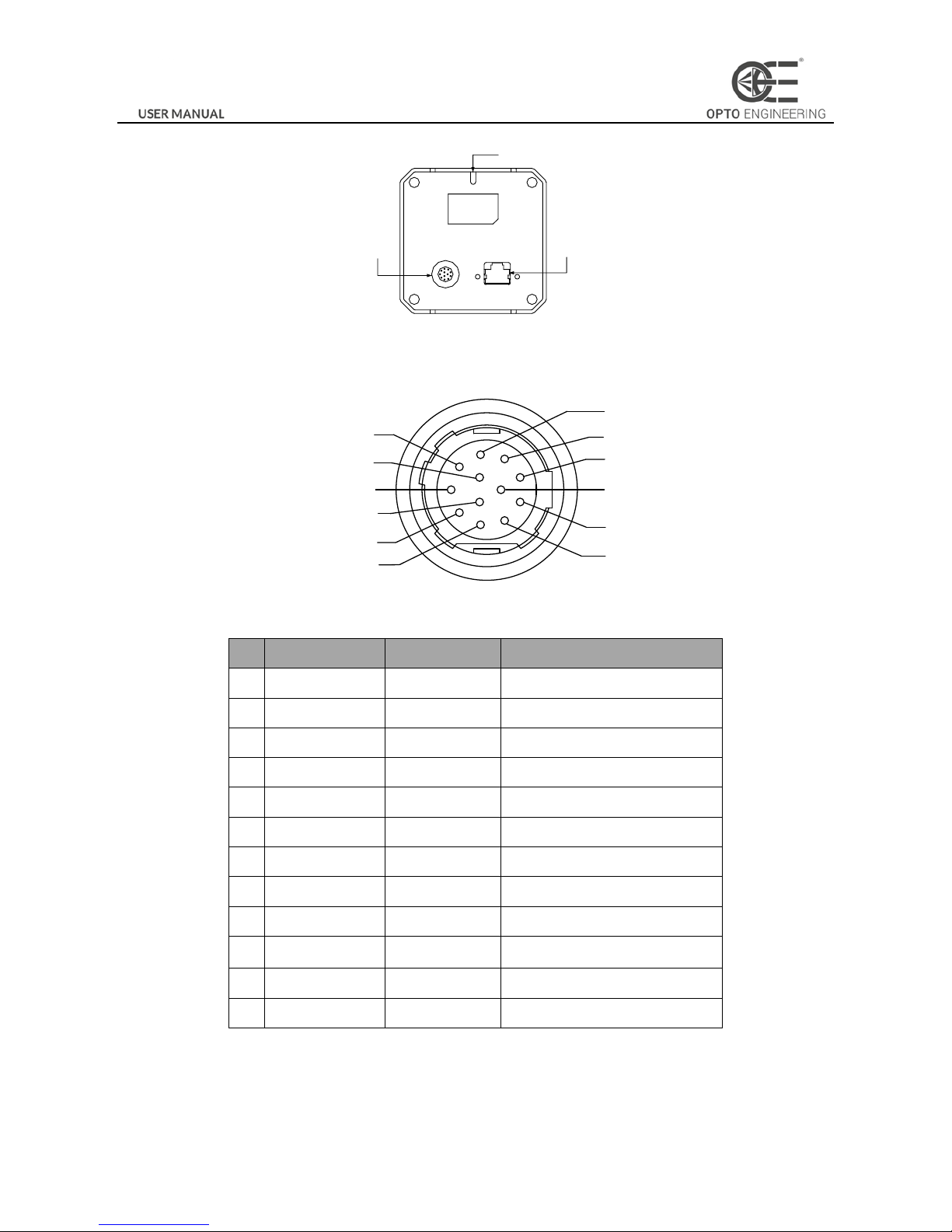
1.3.1 Rear Panel Introduction
The rear panel of the COE camera is shown in the figure below.
7
Indicator (LED)
RJ45 gigabit
Ethernet interface
I/O Interface
Figure 1-3 Rear Panel
1.3.2 Power and I/O Interface Introduction
The description of the 12-pin power and I/O connector is shown in the table below.
1
2
3
4
5
6
7
8
9
10
11
12
Figure 1-4 Power and I/O Interface
Table 1-1 Description
No.
Signal
I/O Type
Description
1
GND
Input
Power ground
2
DC_PWR
Input
DC 12V
3
TX485+
Output
TX485+
4
TX485-
Output
TX485-
5
GND_IO
Input
Isolated ground
6
RX485+
Input
RX485+
7
RX485-
Input
RX485-
8
232_RXD
Input
RS232_TXD
9
232_TXD
Output
RS232_TXD
10
GPIO2
Input/output
Can be configured as input or
output
11
OPTO_OUT0
Output
Opto-isolated output
12
OPTO_IN0
Input
Opto-isolated iuput
Note:
The cable color here specifically refers to the cable provided by our company.

8
1.3.3 Installation Accessories
Prepare the installation accessories listed below before you install the COE camera.
Table 1-2 Accessory List
No.
Accessory Name
Number
Description
1
Camera
1
The COE camera.
2
Power I/O cable
1
The 12-pin cable (included) or extension cable (not included).
3
Power adapter
1
12V DC power adapter (Min. 1.5 A)
4
Ethernet cable with
proper length
1
CAT-5e or CAT-6 Ethernet cable
5
Lens (Optional)
1
M58 Lens or F lens
6
Adapter Ring
(Optional)
1
Adapter ring is necessary when switching the lens.

Chapter 2 Camera Installation and Configuration
2.1 Installing the Camera
Steps:
1. Unpack the camera package and install the lens (optional) to the camera body by rotating the lens clockwise.
2. Fix the camera to the desired position.
3. Use CAT-5e or CAT-6 network cable to connect the camera with a switch or a network card.
4. Choose a power supply method.
Direct supply: Use the supplied cord with a 12-pin power and I/O interface to connect the camera to a power
adapter (DC 12V for the camera).
Note:
The machine vision network camera adopts a gigabit network interface. To guarantee the bandwidth for real-time image
transmission, you need to use a CAT-5e or CAT-6 network cable.
2.2 Network Configuration
Purpose:
Before using the camera, you need to configure the IP address of the camera. The IP addresses of the camera and the local
computer should belong to the same network segment. You can use the ping command on the local computer to test the
network connectivity.
Before you start:
Download the OECS control client from OPTO-E.COM website in the specific series download page. Refer to the
User
Manual of OECS Client Software
for details.
2.2.1 Local Network Configuration
Steps:
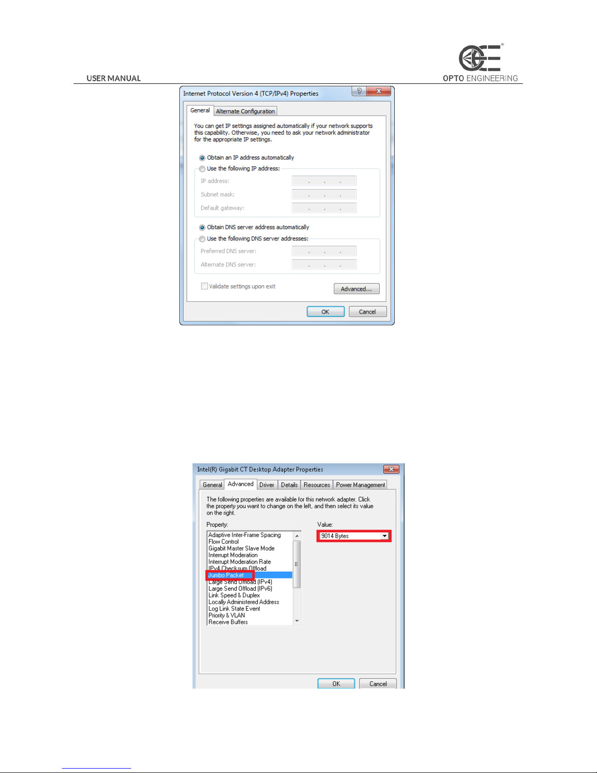
1. Click Start -> Control Panel -> Network and Internet -> Network and Sharing Center -> Change adapter settings,
select the network connection and click Properties.
2. Double click the TCP protocol, and you can set select Obtain an IP address automatically.
3. (Optional) You can also select Use the following IP address, and set the IP address as the same subnet with the
camera.
10
Figure 2-1 IP Address Setting
4. Click OK to save the settings.
5. You also need to enable the jumbo frame of the NIC. For different operating systems, the path to setting the jumbo
frame may be different. Here we take Windows 7 as an example.
1) Click Start -> Control Panel -> Device Manager -> Network adapters, double click the NIC to enter its properties
interface.
2) Click Advanced tab.
3) Select Jumbo Packet from the property list and select the value as 9KB MTU.
4) Click OK to save the settings.
Figure 2-2 Jumbo Packet Settings
11
Note:
Jumbo packet is not supported by some types of NIC. We recommend you to use the NIC which supports jumbo packet for
better image transmission.
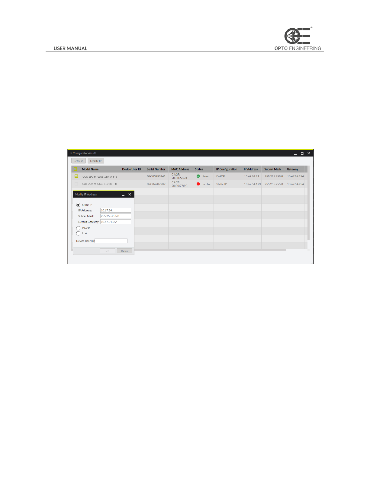
2.2.2 Camera IP Configuration
You can use the client software to complete network configuration for the camera.
Steps:
1. Double click the “OECS IP Configurator.exe” to open the configuration tool. You can find the tool in the installation
directory.
2. Select the camera to configure.
Figure 2-3 Camera Network Parameters Setting (1)
3. You can view the camera status and modify the settings.
If the camera status is Free, the camera is available and you can edit its IP address.
If the camera status is In Use, it means the client software or other processes are accessing the camera. You need
to stop the live view and disconnect the camera, or terminate other processes to access the camera.
If the camera status is Not Reachable, the network of the camera is exceptional and you should check the camera
network settings.
Note:
The camera status may be In Use if the camera IP address is conflicted with other devices. Please make sure the IP address is
not busy before setting the camera IP address.
4. If the camera status is Free, you can edit its IP address.
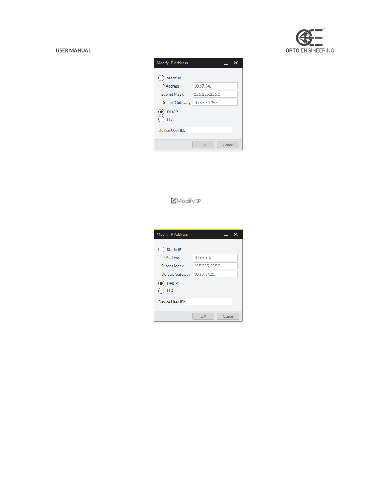
1) Select the IP type as Static IP, DHCP, or LLA.
12
Figure 2-4 Camera Network Parameters Setting (2)
If you set the IP type as Static IP, you can set the IP address, subnet mask, and default gateway.
You can also edit the the camera name in Device User ID field.
Click Save to save the settings.
2) Select the camera to be edited and click button.
3) In the pop-up window, you can edit the IP address of the camera. For Static IP type, you can also edit the subnet
mask and default gateway.
Figure 2-5 Camera Network Parameters Setting (3)
4) Click OK to save the settings.
2.3 Camera Configuration
Note:
Configure the camera via the control client. There are two methods available: setting via the attribute tree or via the menu
bar.
2.3.1 Setting via Attribute Tree
The software can read the XML file of camera attributes and display it in tree format.
Steps:
1. Double click the OECS icon to open the client software. The main user interface and the description of the client

13
software are shown in Figure 2-6 and Table 2-1.
Figure 2-6 Main User Interface of the Client Software
Table 2-1 Description of the Main User Interface
No.
Area Name
Description
1
Menu Bar
Function modules including File, View, Camera, Settings, Tools, and
Help.
2
Control Toolbar
The control toolbar.
3
Device List Panel
Display the GigE Vision camera and USB3 Vision camera, and provide
icons for connecting/disconnecting camera, start/stop acquisition, and
refreshing device list.
4
Interface and Device
Information Panel
Display the network interface information and the device information.
5
Live View Area
View the live video of the selected COE camera.
6
Feature Panel
View and configure features of the selected camera, and perform
other operations such as importing, exporting, and saving features.
Note:
For detailed information, refer to the
User Manual of OECS Control Client
.
2. Double click the camera in Device List Panel.
3. Click the Feature Tree tab to enter the camera attribute page.
Note:
You can switch the user level as Beginner, Expert or Guru which displays different camera attributes. For Guru Level, it
provides the most comprehensive camera attributes for professional use. Here we take Guru Level as an example.
 Loading...