

Page 1
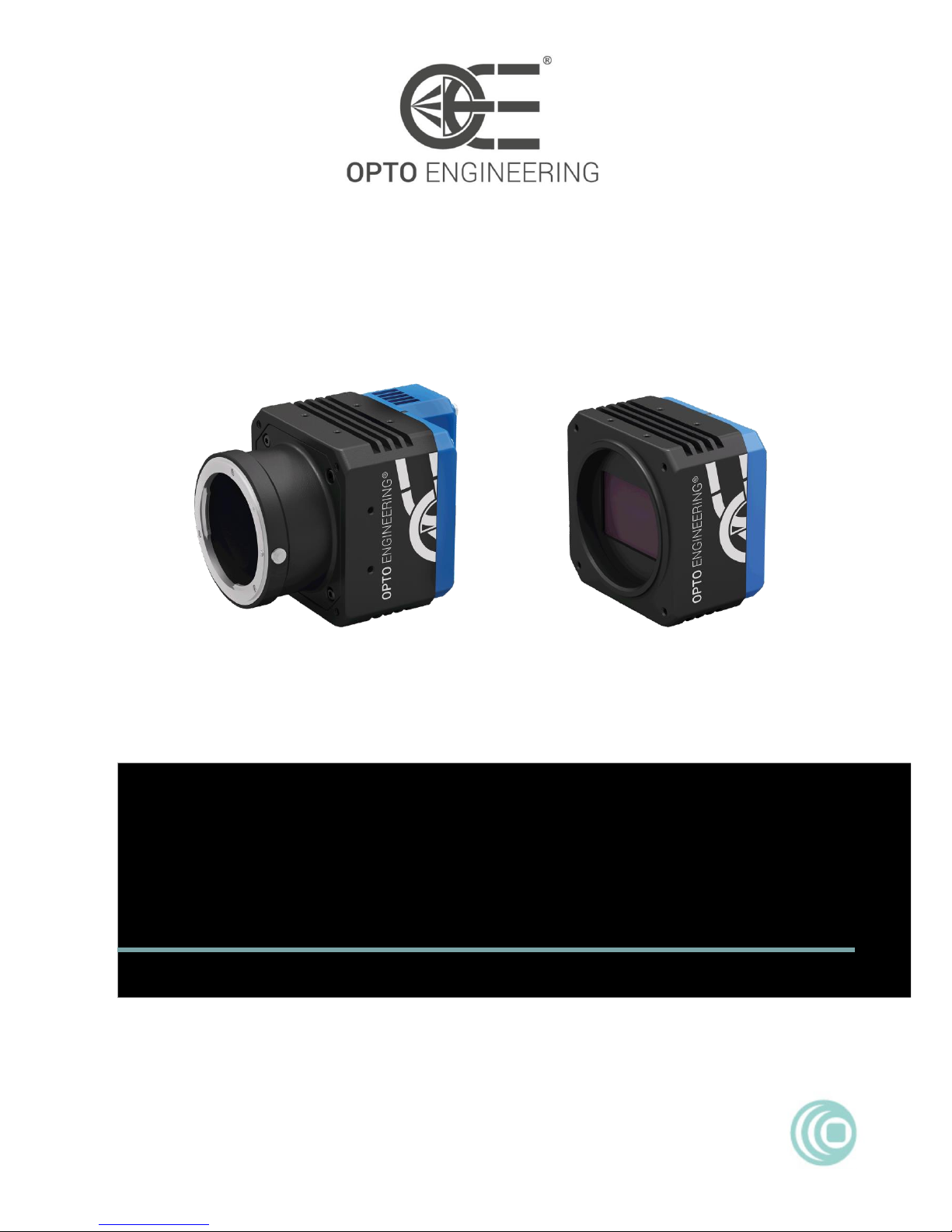
COE-260 & COE-290
GigE Camera
USER MANUAL
V1.0
CAMERAS
COE HR AS-X series
Page 2

1
User Manual
About this Manual
This Manual is applicable to COE HR AS-X series GigE cameras.
The Manual includes instructions for using and managing the product. Pictures, charts, images and all other information
hereinafter are for description and explanation only. The information contained in the Manual is subject to change, without
notice, due to firmware updates or other reasons. Please find the latest version in the company website.
Please use this user manual under the guidance of professionals.
Legal Disclaimer
TO THE MAXIMUM EXTENT PERMITTED BY APPLICABLE LAW, THE PRODUCT DESCRIBED, WITH ITS HARDWARE,
SOFTWARE AND FIRMWARE, IS PROVIDED "AS IS", WITH ALL FAULTS AND ERRORS, AND OUR COMPANY MAKES NO
WARRANTIES, EXPRESS OR IMPLIED, INCLUDING WITHOUT LIMITATION, MERCHANTABILITY, SATISFACTORY
QUALITY, FITNESS FOR A PARTICULAR PURPOSE, AND NON-INFRINGEMENT OF THIRD PARTY. IN NO EVENT WILL
OUR COMPANY, ITS DIRECTORS, OFFICERS, EMPLOYEES, OR AGENTS BE LIABLE TO YOU FOR ANY SPECIAL,
CONSEQUENTIAL, INCIDENTAL, OR INDIRECT DAMAGES, INCLUDING, AMONG OTHERS, DAMAGES FOR LOSS OF
BUSINESS PROFITS, BUSINESS INTERRUPTION, OR LOSS OF DATA OR DOCUMENTATION, IN CONNECTION WITH THE
USE OF THIS PRODUCT, EVEN IF OUR COMPANY HAS BEEN ADVISED OF THE POSSIBILITY OF SUCH DAMAGES.
REGARDING TO THE PRODUCT WITH INTERNET ACCESS, THE USE OF PRODUCT SHALL BE WHOLLY AT YOUR OWN
RISKS. OUR COMPANY SHALL NOT TAKE ANY RESPONSIBILITIES FOR ABNORMAL OPERATION, PRIVACY LEAKAGE
OR OTHER DAMAGES RESULTING FROM CYBER ATTACK, HACKER ATTACK, VIRUS INSPECTION, OR OTHER INTERNET
SECURITY RISKS; HOWEVER, OUR COMPANY WILL PROVIDE TIMELY TECHNICAL SUPPORT IF REQUIRED.
SURVEILLANCE LAWS VARY BY JURISDICTION. PLEASE CHECK ALL RELEVANT LAWS IN YOUR JURISDICTION BEFORE
USING THIS PRODUCT IN ORDER TO ENSURE THAT YOUR USE CONFORMS THE APPLICABLE LAW. OUR COMPANY
SHALL NOT BE LIABLE IN THE EVENT THAT THIS PRODUCT IS USED WITH ILLEGITIMATE PURPOSES.
IN THE EVENT OF ANY CONFLICTS BETWEEN THIS MANUAL AND THE APPLICABLE LAW, THE LATER PREVAILS.
Warning
This is a class A product. In a domestic environment this product may cause radio interference in which case the user may be
required to take adequate measures.
Safety Instruction
These instructions are intended to ensure that the user can use the product correctly to avoid danger or property loss.
The precaution measure is divided into ‘Warnings’ and ‘Cautions’:
Warnings: Serious injury or death may be caused if any of these warnings are neglected.
Cautions: Injury or equipment damage may be caused if any of these cautions are neglected.
Warnings Follow these safeguards to prevent
serious injury or death.
Cautions Follow these precautions to prevent
potential injury or material damage.
Warnings:
Please adopt the power adapter which can meet the safety extra low voltage (SELV) standard. And source with 12 VDC
(depending on models) according to the IEC60950-1 and Limited Power Source standard.
To reduce the risk of fire or electrical shock, do not expose this product to rain or moisture.
This installation should be made by a qualified service person and should conform to all the local codes.
Please install blackouts equipment into the power supply circuit for convenient supply interruption.
Please make sure that the ceiling can support more than 50(N) Newton gravities if the camera is fixed to the ceiling.
Page 3
2
If the product does not work properly, please contact your dealer or the nearest service center. Never attempt to
disassemble the camera yourself. (We shall not assume any responsibility for problems caused by unauthorized repair or
maintenance.)
Cautions:
Make sure the power supply voltage is correct before using the camera.
Do not drop the camera or subject it to physical shock.
Do not touch sensor modules with fingers. If cleaning is necessary, use a clean cloth with a bit of ethanol and wipe it
gently. If the camera will not be used for an extended period of time, put on the lens cap to protect the sensor from dirt.
Do not aim the camera lens at the strong light such as sun or incandescent lamp. The strong light can cause fatal damage
to the camera.
The sensor may be burned out by a laser beam, so when any laser equipment is being used, make sure that the surface of
the sensor not be exposed to the laser beam.
Do not place the camera in extremely hot, cold temperatures (the operating temperature should be between -0°C to
50°C), dusty or damp environment, and do not expose it to high electromagnetic radiation.
To avoid heat accumulation, ensure there is good ventilation to the device.
Keep the camera away from water and any liquids.
While shipping, pack the camera in its original, or equivalent, packing materials. Or packing the same texture.
Improper use or replacement of the battery may result in hazard of explosion. Please use the manufacturer
recommended battery type.
Page 4
3
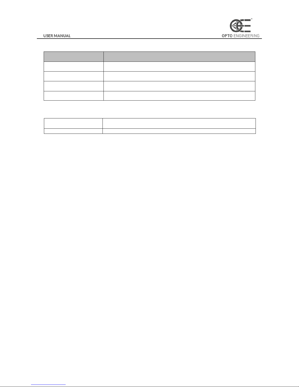
Part Number
Part number
Description
COE-260-M-10GIGE-100-IR
CMOS, Python 25K, APS−H, 5120x5120, 4.5pix, F mount, M58x0.75 FD11.48
COE-290-x-GIGE-110-yy-B
CCD, KAI-29050, 35mm, 6576x4384, 4.5pix,F mount, M58x0.75 FD11.48, GIGE
COE-290-M-GIGE-110-IR-A
CCD, KAI-29050, 35mm, 6576x4384, 4.5pix,F mount, M58x0.75 FD11.48, GIGE
COE-290-M-GIGE-110-IR-I-N
CCD, KAI-29050, 35mm, 6576x4384, 4.5pix, M58x0.75 FD11.48, GIGE
How to Order
X
M = Monochrome
C = Color
YY
Glass/Infrared cut filter supported
Page 5

4
Table of Contents
Chapter 1 Overview
................................................................................................................................................................... 6
1.1 Introduction............................................................................................................................. 6
1.2 Main Features .......................................................................................................................... 6
1.3 Camera Physical Interfaces ....................................................................................................... 6
1.3.1 Rear Panel Introduction ................................................................................................................................ 6
1.3.2 Power and I/O Interface Introduction ........................................................................................................... 7
1.3.3 Installation Accessories ................................................................................................................................. 8
Chapter 2 Camera Installation and Configuration
................................................................................................................... 9
2.1 Installing the Camera ............................................................................................................... 9
2.2 Network Configuration ............................................................................................................. 9
2.2.1 Local Network Configuration ........................................................................................................................ 9
2.2.2 Camera IP Configuration ............................................................................................................................. 11
2.3 Camera Configuration ............................................................................................................ 12
2.3.1 Setting via Attribute Tree ............................................................................................................................ 12
Chapter 3 Functions
................................................................................................................................................................. 15
3.1 Device Control ....................................................................................................................... 15
3.1.1 Name Modification ..................................................................................................................................... 15
3.2 Image Format and Frame Rate ................................................................................................ 16
3.2.1 Camera Data Format ................................................................................................................................... 16
3.2.2 Frame Rate .................................................................................................................................................. 16
3.2.3 ROI Setting .................................................................................................................................................. 17
3.3 Image Acquisition and Transmission ....................................................................................... 17
3.3.1 Internal Trigger Mode ................................................................................................................................. 18
3.3.2 External Trigger Signal and Working Mode ................................................................................................. 18
3.4 Strobe Output ........................................................................................................................ 20
3.5 Acquisition Mode under External Trigger ................................................................................ 22
3.6 Counter Control ..................................................................................................................... 23
3.7 Imaging Parameter Setting ..................................................................................................... 24
3.7.1 Exposure Time ............................................................................................................................................ 24
3.7.2 Gain Control ................................................................................................................................................ 24
3.7.3 White balance ............................................................................................................................................. 25
3.7.4 Area Setting of Auto Functions ................................................................................................................... 25
3.7.5 Look Up Table (LUT) .................................................................................................................................... 26
3.7.6 Gamma Correction ...................................................................................................................................... 26
3.7.7 Brightness, Hue and Saturation .................................................................................................................. 27
3.7.8 Image Reverse ............................................................................................................................................. 28
3.7.9 Test pattern ................................................................................................................................................. 28
3.8 I/O Electric Feature ................................................................................................................ 30
3.8.1 Line0 Opto-isolated Input Circuit ................................................................................................................ 30
3.8.2 Line1 Opto-isolated Output Circuit ............................................................................................................. 31
3.8.3 Line2 Configurable Bi-direction I/O Circuit ................................................................................................. 32
3.8.4 RS-485 ......................................................................................................................................................... 34
3.9 Transport Layer Control .......................................................................................................... 34
3.9.1 DHCP and Persistent IP................................................................................................................................ 34
Page 6

5
3.9.2 Efficient Bandwidth and Setting .................................................................................................................. 35
3.10 User Parameter and Preference Setting ................................................................................... 36
3.10.1 Parameters Saving and Loading .................................................................................................................. 36
3.10.2 Embedded Information ............................................................................................................................... 36
3.11 Firmware Updating ................................................................................................................ 38
Chapter 4 Revision History
...................................................................................................................................................... 40
Chapter 5 Trouble Shooting
..................................................................................................................................................... 41
5.1 Indicator Status Definition ...................................................................................................... 41
5.2 Indicator Status Description ................................................................................................... 41
5.3 FAQ ....................................................................................................................................... 42
Page 7

6
Chapter 1 Overview
1.1 Introduction
The COE camera is an image capturing device capable of real-time transmission of uncompressed image through a gigabit
Ethernet interface. Remote image capturing and camera control, for example, the operating mode and the image parameters
adjustment, are supported by client software.
1.2 Main Features
The gigabit Ethernet interface provides the bandwidth of 1 Gbps and reaches the maximum transmission distance of
100 meters.
128 MB onboard memory stores images for burst transmission and retransmission.
Supports AEC (automatic exposure control), LUT, Gamma Correction, etc..
Use hardware external trigger or software trigger to synchronize several cameras or cameras with external devices.
Supports image capturing with different exposure modes.
Compatible with GigE Vision Protocol (V1.2) and third-party software.
RS232 and RS485
Note:
The functions in this manual are for reference only and may differ from the devices.
1.3 Camera Physical Interfaces
The dimensions of the COE camera are shown below.
Figure 1-1 M58-Mount without Fan
20
2-M2 4
74
74
60
4-M3 5
60
24.5
24.5
11.38
53.88
84.88
OPTICAL DISTANCE
46.5
-0.15
+0.05
4-M3 3
Φ58
113
Unit: mm
Figure 1-2 F-Mount with Fan
1.3.1 Rear Panel Introduction
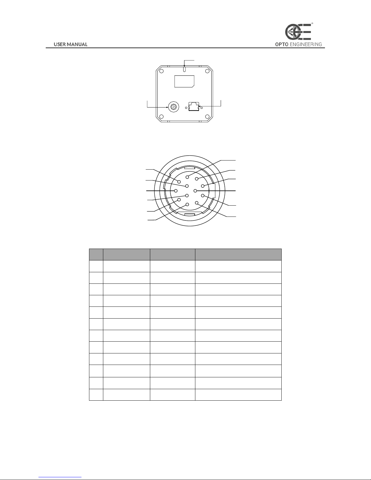
The rear panel of the COE camera is shown in the figure below.
Page 8
7
Indicator (LED)
RJ45 gigabit
Ethernet interface
I/O Interface
Figure 1-3 Rear Panel
1.3.2 Power and I/O Interface Introduction
The description of the 12-pin power and I/O connector is shown in the table below.
1
2
3
4
5
6
7
8
9
10
11
12
Figure 1-4 Power and I/O Interface
Table 1-1 Description
No.
Signal
I/O Type
Description
1
GND
Input
Power ground
2
DC_PWR
Input
DC 12V
3
TX485+
Output
TX485+
4
TX485-
Output
TX485-
5
GND_IO
Input
Isolated ground
6
RX485+
Input
RX485+
7
RX485-
Input
RX485-
8
232_RXD
Input
RS232_TXD
9
232_TXD
Output
RS232_TXD
10
GPIO2
Input/output
Can be configured as input or
output
11
OPTO_OUT0
Output
Opto-isolated output
12
OPTO_IN0
Input
Opto-isolated iuput
Note:
The cable color here specifically refers to the cable provided by our company.
Page 9

8
1.3.3 Installation Accessories
Prepare the installation accessories listed below before you install the COE camera.
Table 1-2 Accessory List
No.
Accessory Name
Number
Description
1
Camera
1
The COE camera.
2
Power I/O cable
1
The 12-pin cable (included) or extension cable (not included).
3
Power adapter
1
12V DC power adapter (Min. 1.5 A)
4
Ethernet cable with
proper length
1
CAT-5e or CAT-6 Ethernet cable
5
Lens (Optional)
1
M58 Lens or F lens
6
Adapter Ring
(Optional)
1
Adapter ring is necessary when switching the lens.
Page 10

Chapter 2 Camera Installation and Configuration
2.1 Installing the Camera
Steps:
1. Unpack the camera package and install the lens (optional) to the camera body by rotating the lens clockwise.
2. Fix the camera to the desired position.
3. Use CAT-5e or CAT-6 network cable to connect the camera with a switch or a network card.
4. Choose a power supply method.
Direct supply: Use the supplied cord with a 12-pin power and I/O interface to connect the camera to a power
adapter (DC 12V for the camera).
Note:
The machine vision network camera adopts a gigabit network interface. To guarantee the bandwidth for real-time image
transmission, you need to use a CAT-5e or CAT-6 network cable.
2.2 Network Configuration
Purpose:
Before using the camera, you need to configure the IP address of the camera. The IP addresses of the camera and the local
computer should belong to the same network segment. You can use the ping command on the local computer to test the
network connectivity.
Before you start:
Download the OECS control client from OPTO-E.COM website in the specific series download page. Refer to the
User
Manual of OECS Client Software
for details.
2.2.1 Local Network Configuration
Steps:
1. Click Start -> Control Panel -> Network and Internet -> Network and Sharing Center -> Change adapter settings,
select the network connection and click Properties.
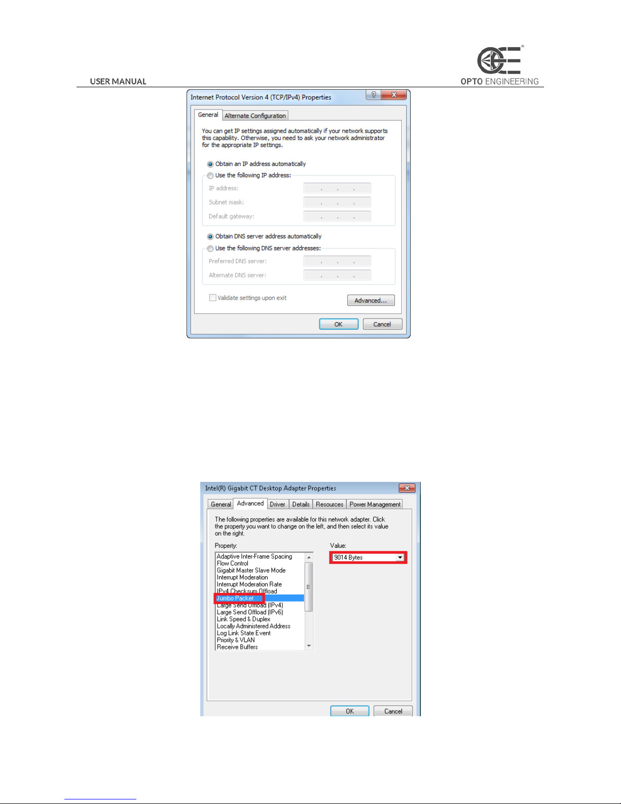
2. Double click the TCP protocol, and you can set select Obtain an IP address automatically.
3. (Optional) You can also select Use the following IP address, and set the IP address as the same subnet with the
camera.
Page 11
10
Figure 2-1 IP Address Setting
4. Click OK to save the settings.
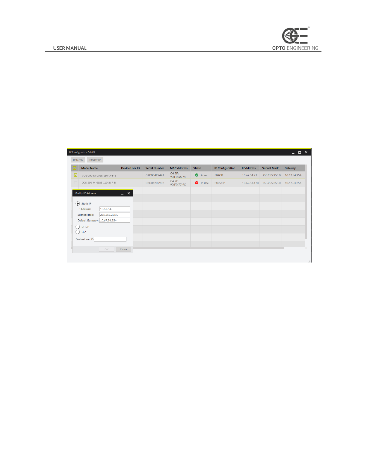
5. You also need to enable the jumbo frame of the NIC. For different operating systems, the path to setting the jumbo
frame may be different. Here we take Windows 7 as an example.
1) Click Start -> Control Panel -> Device Manager -> Network adapters, double click the NIC to enter its properties
interface.
2) Click Advanced tab.
3) Select Jumbo Packet from the property list and select the value as 9KB MTU.
4) Click OK to save the settings.
Figure 2-2 Jumbo Packet Settings
Page 12
11
Note:
Jumbo packet is not supported by some types of NIC. We recommend you to use the NIC which supports jumbo packet for
better image transmission.
2.2.2 Camera IP Configuration
You can use the client software to complete network configuration for the camera.
Steps:
1. Double click the “OECS IP Configurator.exe” to open the configuration tool. You can find the tool in the installation
directory.
2. Select the camera to configure.
Figure 2-3 Camera Network Parameters Setting (1)
3. You can view the camera status and modify the settings.
If the camera status is Free, the camera is available and you can edit its IP address.
If the camera status is In Use, it means the client software or other processes are accessing the camera. You need
to stop the live view and disconnect the camera, or terminate other processes to access the camera.
If the camera status is Not Reachable, the network of the camera is exceptional and you should check the camera
network settings.
Note:
The camera status may be In Use if the camera IP address is conflicted with other devices. Please make sure the IP address is
not busy before setting the camera IP address.
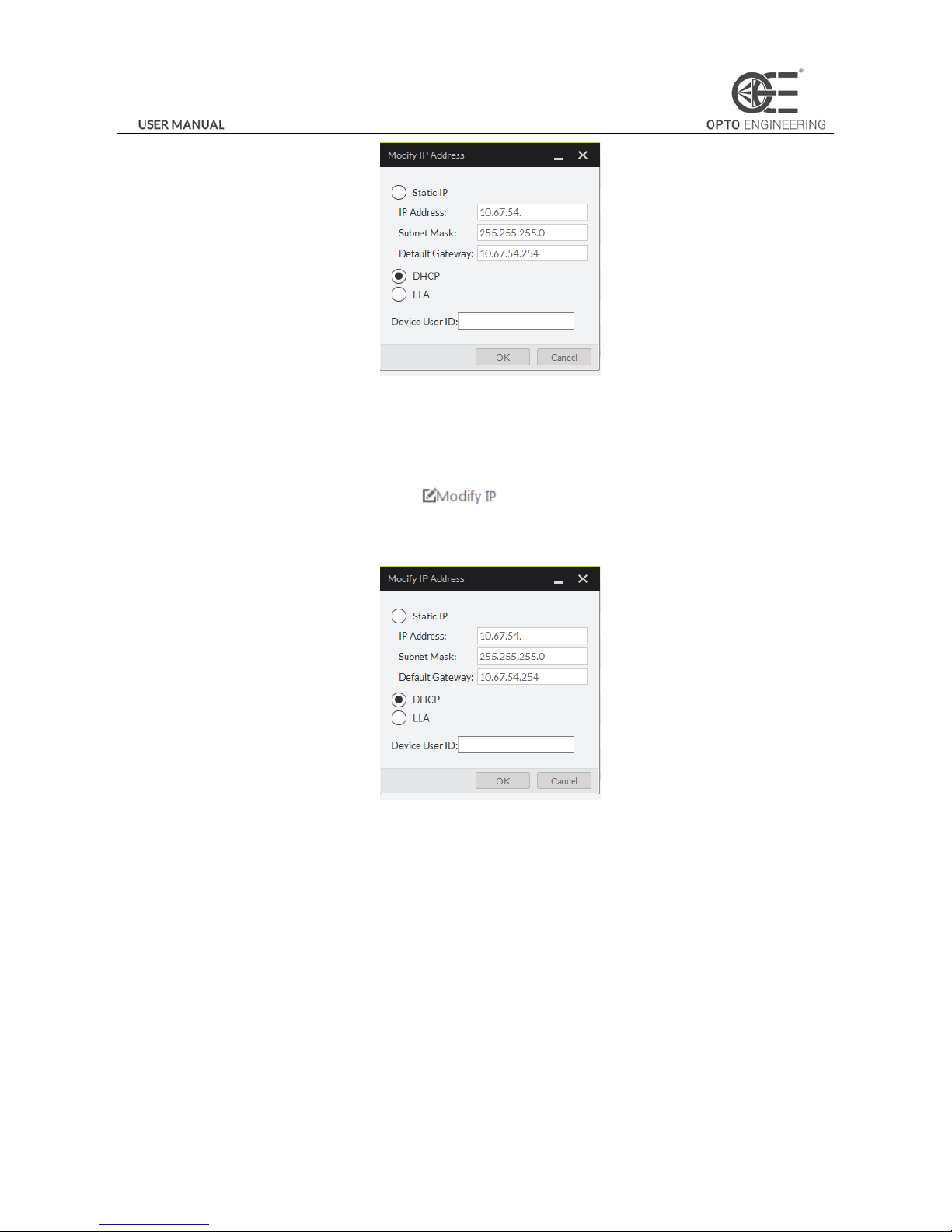
4. If the camera status is Free, you can edit its IP address.
1) Select the IP type as Static IP, DHCP, or LLA.
Page 13
12
Figure 2-4 Camera Network Parameters Setting (2)
If you set the IP type as Static IP, you can set the IP address, subnet mask, and default gateway.
You can also edit the the camera name in Device User ID field.
Click Save to save the settings.
2) Select the camera to be edited and click button.
3) In the pop-up window, you can edit the IP address of the camera. For Static IP type, you can also edit the subnet
mask and default gateway.
Figure 2-5 Camera Network Parameters Setting (3)
4) Click OK to save the settings.
2.3 Camera Configuration
Note:
Configure the camera via the control client. There are two methods available: setting via the attribute tree or via the menu
bar.
2.3.1 Setting via Attribute Tree
The software can read the XML file of camera attributes and display it in tree format.
Steps:
1. Double click the OECS icon to open the client software. The main user interface and the description of the client
Page 14

13
software are shown in Figure 2-6 and Table 2-1.
Figure 2-6 Main User Interface of the Client Software
Table 2-1 Description of the Main User Interface
No.
Area Name
Description
1
Menu Bar
Function modules including File, View, Camera, Settings, Tools, and
Help.
2
Control Toolbar
The control toolbar.
3
Device List Panel
Display the GigE Vision camera and USB3 Vision camera, and provide
icons for connecting/disconnecting camera, start/stop acquisition, and
refreshing device list.
4
Interface and Device
Information Panel
Display the network interface information and the device information.
5
Live View Area
View the live video of the selected COE camera.
6
Feature Panel
View and configure features of the selected camera, and perform
other operations such as importing, exporting, and saving features.
Note:
For detailed information, refer to the
User Manual of OECS Control Client
.
2. Double click the camera in Device List Panel.
3. Click the Feature Tree tab to enter the camera attribute page.
Note:
You can switch the user level as Beginner, Expert or Guru which displays different camera attributes. For Guru Level, it
provides the most comprehensive camera attributes for professional use. Here we take Guru Level as an example.
Page 15
14
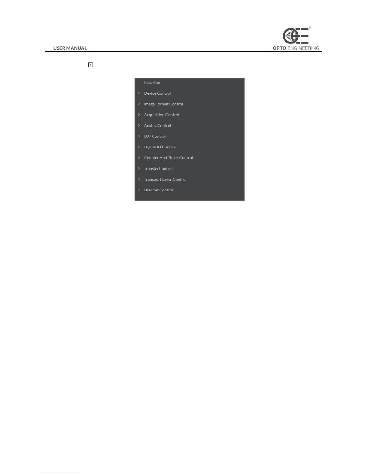
4. Click the icon before each attribute to view and edit the details.
Figure 2-7 Attribute Page
Device Control: In the Device Control attribute, you can view the camera details and modify the camera name.
Image Format Control: In the Image Format Control attribute, you can view the live view image width and height, pixel
size, etc. You can modify the image reverse status, test pattern and the embedded information, etc.
Acquisition Control: In the Acquisition Control attribute, you can set the trigger mode, trigger source, exposure details,
etc.
Analog Control: In the Analog Control attribute, you can adjust analog gain, black level, gamma, sharpness, AOI, etc.
LUT Control: In the LUT Control attribute, you can view the user lookup table and set the LUT index and value.
Digital IO Control: In the Digital IO Control attribute, you can manage the digital input and output.
Counter and Timer Control: In the Counter and Timer Control attribute, you can set the counter and timer function.
Transport Layer Control: In the Transport Layer Control attribute, you can set the parameters of transport layer of the
camera.
User Set Control: In the User Set Control attribute, you can save or load the parameter configuration set by users. You
can set the default parameter when running the software.
Note:
Functions and Attributes of COE cameras may be different among different camera models.
Page 16
15
Chapter 3 Functions
3.1 Device Control
3.1.1 Name Modification
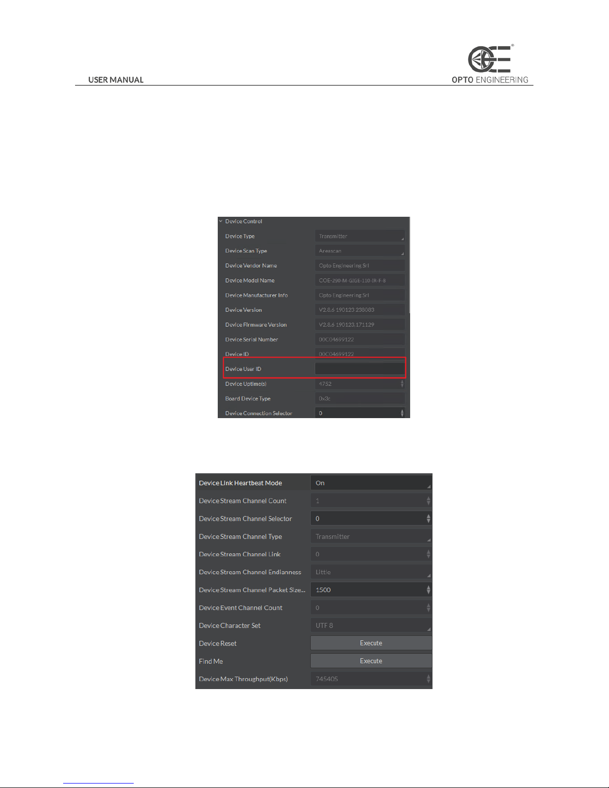
Run client software and click Device Control. You will see the device type, the version information, the device serial number
and so on. Input the device name in Device User ID as shown in Figure 3-1.
Figure 3-1 Device Name Modification
You can turn on the heartbeat detection mechanism, reset the device, and view the device temperature in Device Control, as
shown in Figure 3-2.
Figure 3-2 Device Information
Page 17
16
3.2 Image Format and Frame Rate
Support different image formats and customized image formats.
Note:
The following figures are for reference only. The actual format depends on the camera’s supported formats.
3.2.1 Camera Data Format
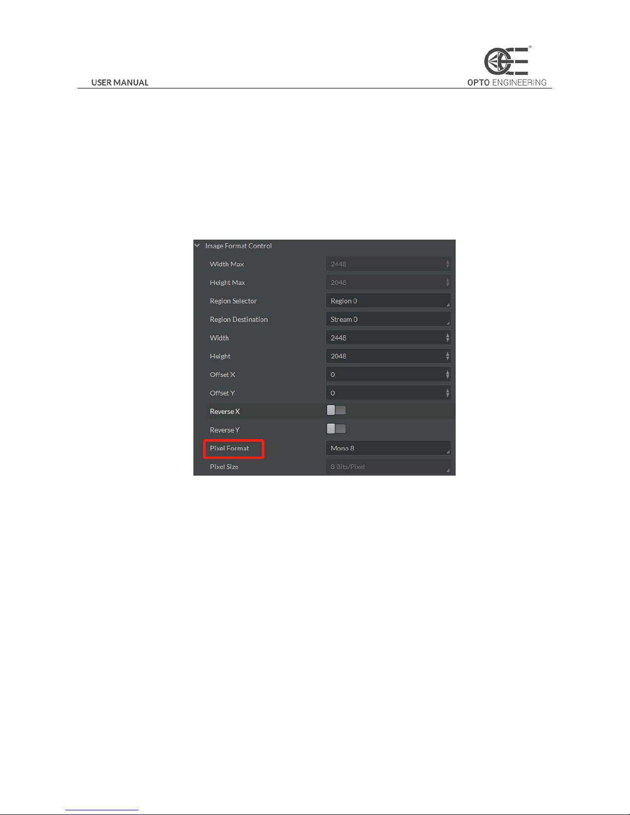
Click Image Format Control in the attribute list and select Pixel Format. You will find the supported pixel format. Choose the
appropriate data output format as shown in Figure 3-3 and finish the setting.
Figure 3-3 Frame Rate Setting
3.2.2 Frame Rate
The network transmission bandwidth, pixel format, and output ROI resolution decides the maximum camera frame rate.
Refer to the frame rate formula when setting ROI.
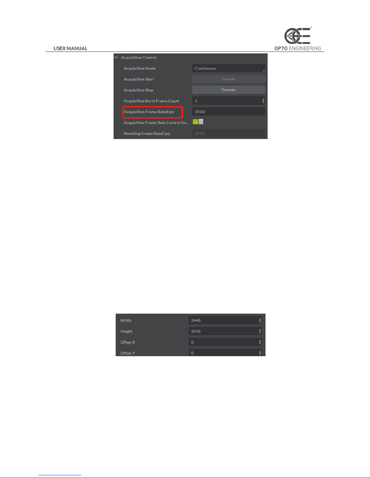
Click Acquisition Control in the attribute list and select Acquisition Frame Rate. Input available frame rate as shown in Figure
3-4 and finish setting.
Page 18
17
Figure 3-4 Frame Rate Setting
3.2.3 ROI Setting
The following three factors decide the maximum camera frame rate:
Frame Readout time: the shorter the image height, the less the readout time and the higher the frame rate are.
Exposure time: the less the exposure time, the higher the frame rate is.
Bandwidth: the wider the bandwidth, the higher the frame rate is.
The camera can output ROI images depending on your requirements. ROI setting can decrease the data transmission
bandwidth, and increase the camera frame rate. The following formulas show the frame rate corresponding to the ROI:
Fps1 = 1/(ROI height * T1 + ROI OffsetY * T2 + T3);
Fps2 = 1/Exp Time;
Fps3 = Bandwidth / PayloadSize;
Note:
The lowest frame rate within the three formulas is the Resulting Frame Rate.
Click Image Format Control and find Width, Height, Offset X, and Offset Y. Adjust the value of width, height, and offset X. The
value of Offset X and the Offset Y refer to the ROI starting point at the top left corner, and Offset Y is default as 0. The
following figure shows the ROI setting.
Figure 3-5 ROI Setting
Note:
For more information about bandwidth and Payload Size, refer to the chapter of Transmission Layer Control.
3.3 Image Acquisition and Transmission
Image acquisition mode is divided into internal trigger mode and external trigger mode. Internal trigger mode includes
continuous acquisition mode and single frame acquisition mode. External trigger mode includes software trigger mode and
Page 19
18
hardware external trigger mode.
Select On or Off in Trigger Mode to select either internal trigger mode or external trigger mode. (Off refers to the internal
trigger mode and On refers to the external trigger mode.)
3.3.1 Internal Trigger Mode
The Camera can output one image or several images continuously in the internal trigger mode.
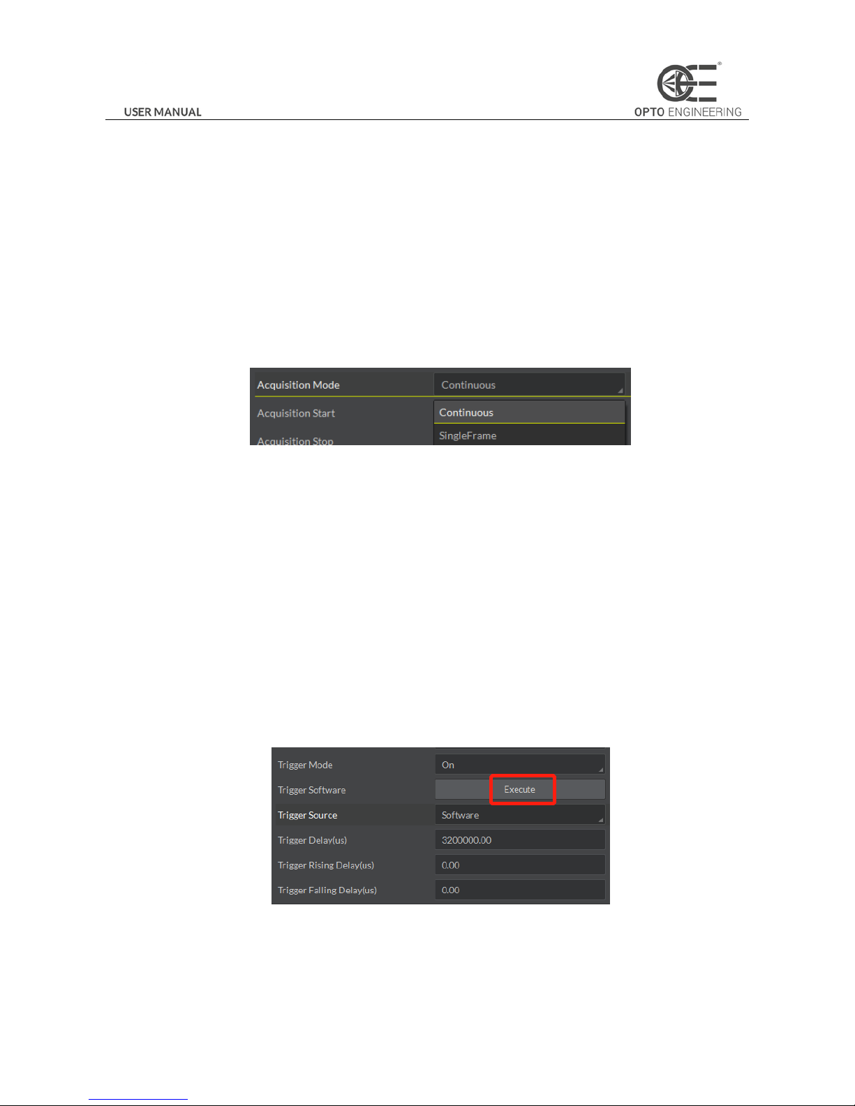
Click Acquisition Control in the attribute list. Select Acquisition Mode and you will see elements of Continuous and Single
Frame. Continuous refers to outputting images continuously based on the configured frame rate. Single Frame refers to
outputting only one image, as shown in Figure 3-6.
Figure 3-6 Internal Trigger Mode
3.3.2 External Trigger Signal and Working Mode
The signal for the camera to acquire external trigger signal includes the software trigger signal and t he signal from external
level.
Under the external trigger signal mode, the camera can output images according to single frame mode, burst mode, PWM
mode and any other working modes.
Software trigger mode
Support software trigger mode. When setting software trigger mode, the client software will send command to the camera to
capture and transfer images by gigabit network.
Click Acquisition Control in the attribute list and select Trigger Mode. Choose On to open trigger mode. Select Trigger Sourc e
and choose Software to switch to the software external trigger status. Click Execute in Trigger Software to trigger image
acquisition, as shown in Figure 3-7.
Figure 3-7 Software Trigger Mode Setting
Hardware external trigger mode
Select Trigger Source and Choose Hardware to switch to the hardware external trigger status.
Page 20
19
Available parameter setting of input signal from hardware external trigger:
(1) Trigger edge selection
Selecting Rising Edge/Falling Edge under the external signal is available.
(2) Trigger delay
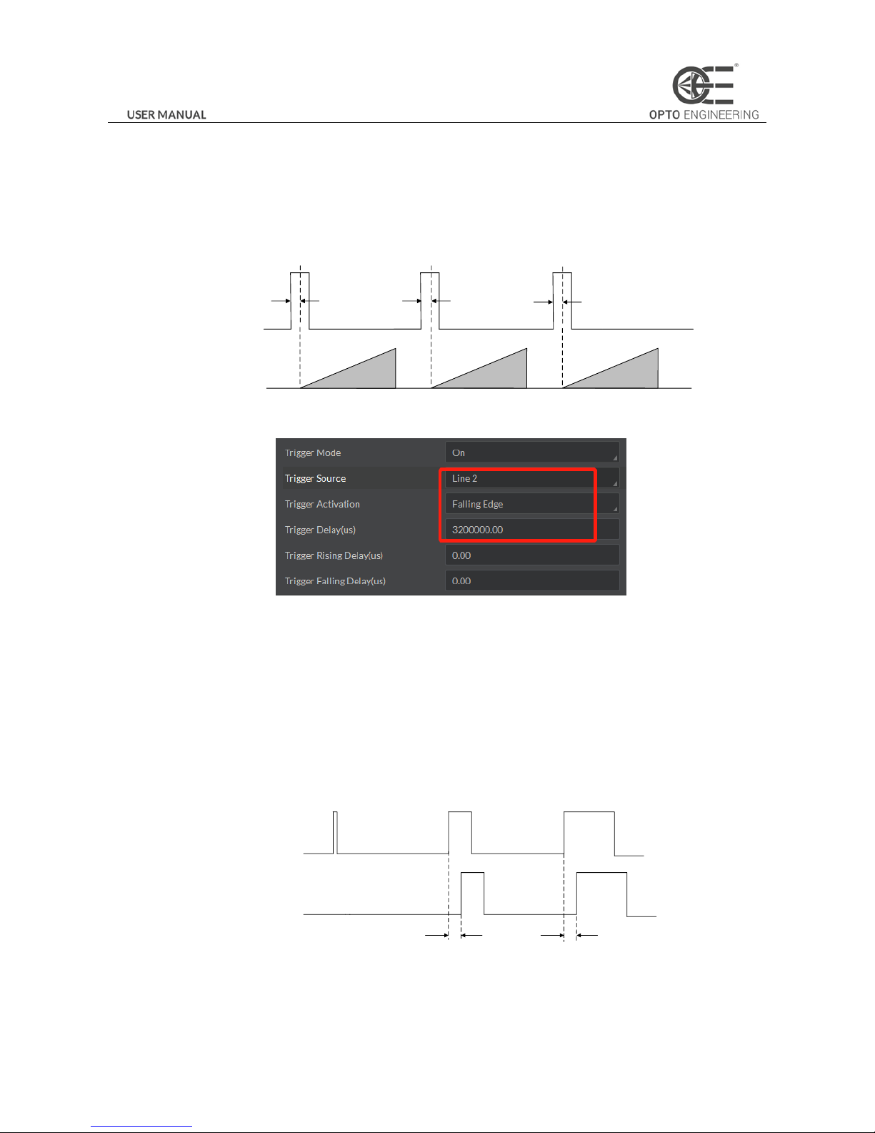
As shown in Figure 3-8, in order to integrate later, the camera can set delay time when receiving the trigger signal. As shown
in Figure 3-9, the delay time can be set through Trigger Delay. The range is from 0 to 32000000 and the unit is μs.
Sensor
exposure
Intergration1 Intergration2 Intergration3
Trigger_in1
Trigger
delay
Trigger_in2
Trigger
delay
Trigger_in3
Trigger
delay
Figure 3-8 Signal Delay Principle
Figure 3-9 Delay Time Setting
(3) Triggering Anti-jitter
The noise may exist in external trigger’s input signal and it may cause spurious triggering status if it goes into the camera.
Thus the debounce is necessary.
The debounce parameter can be set through Line Debouncer Time in the client software. The unit is μs. The timing sequence
map is shown in Figure 3-10. The camera will ignore the trigger signal if the debouncer time is longer than the triggering
signal time.
Trigger_in1 Trigger_in2 Trigger_in3
Trigger_in2 Trigger_in3
Before
debounce
After
debounce
Debouncer Time Debouncer Time
Figure 3-10 The Debounce of Triggering Input Signal Sequence Map
Page 21
20
3.4 Strobe Output
Strobe is external trigger output signal and is used for controlling external devices such as flashing light and so on. You can set
the Strobe polarity, duration, output delay and pre-trigger through the client software.
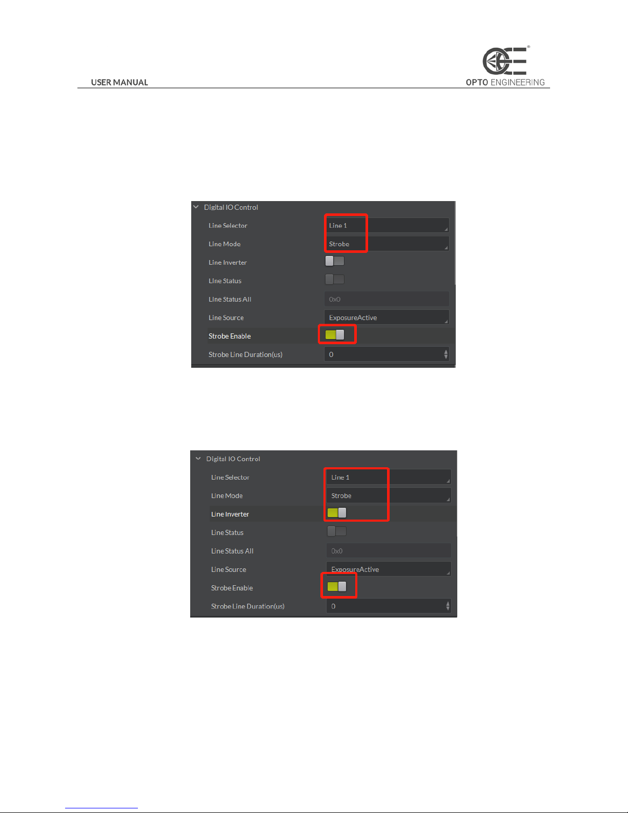
As shown in Figure 3-11, click Digital IO Control. Select Line Selector and choose output pin. Check Strobe Enabled and finish
setting.
Figure 3-11 Strobe Output Mode
Available Strobe parameter setting:
(1) Polarity setting
Tick Line Inverter to set polarity external trigger’s output signal, as shown in Figure 3-12.
Figure 3-12 Modifying Strobe Polarity
(2) Strobe valid time
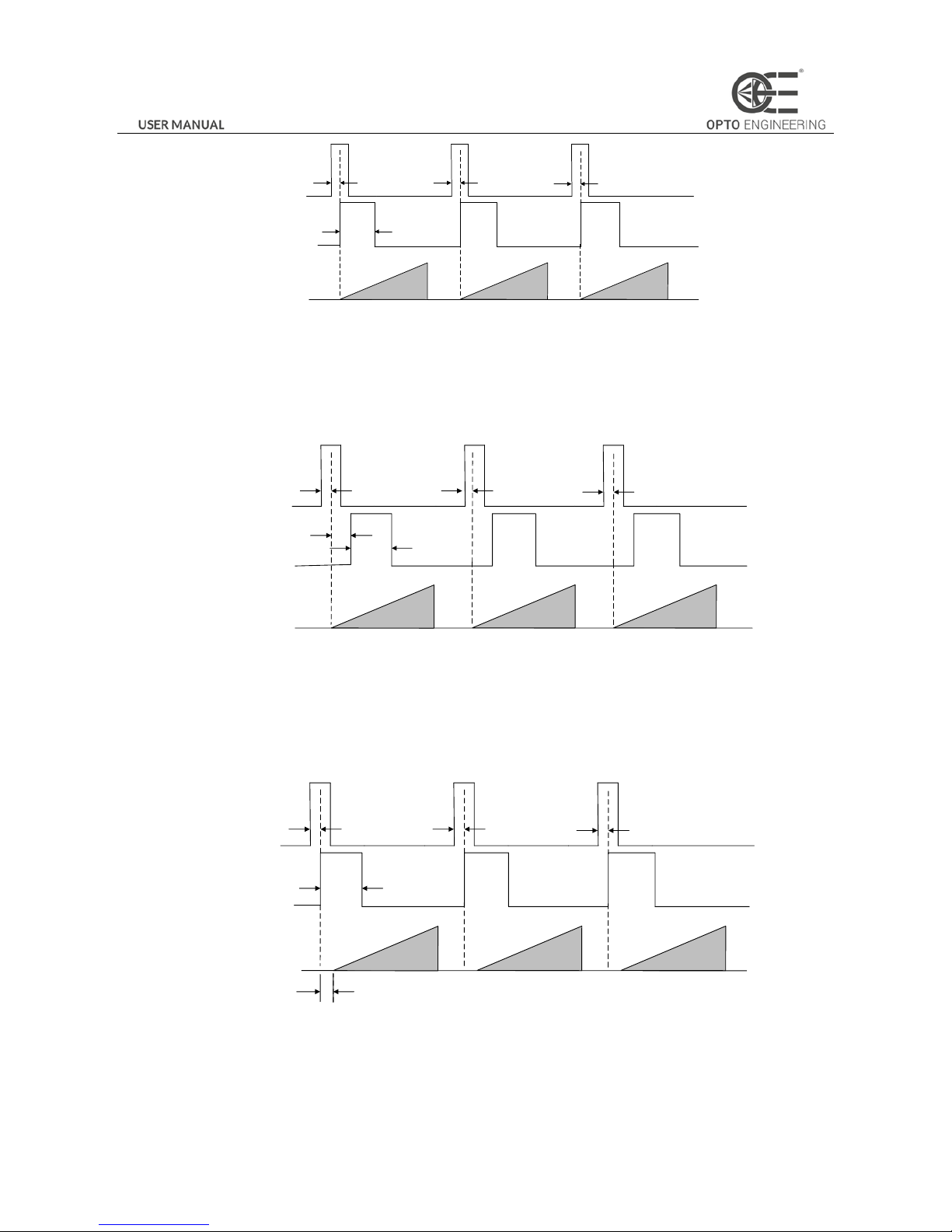
As shown in Figure 3-13, Strobe is set to high level. When exposure starts, Strobe will output immediately. Strobe Line
Duration value decides the Strobe duration: when the Strobe Line Duration value is 0, the Strobe duration is equal to the
exposure time; when the Strobe Line Duration value is not 0, the Strobe duration is equal to Strobe Line Duration value.
Page 22
21
Strobe
Trigger_in1
Sensor
exposure
Intergration1 Intergration2 Intergration3
Trigger
delay
Trigger_in2
Trigger
delay
Trigger_in3
Trigger
delay
Duration
Figure 3-13 Strobe Valid Electrical Level Duration
(3) Strobe output delay
The camera supports the function of Strobe signal output delay to satisfy special applications: as shown in Figure 3-14, when
exposure starts, the Strobe output is not valid immediately. Instead, the Strobe output will delay according to the setting in
Strobe Line Delay.
Strobe
Trigger_in1
Sensor
exposure
Intergration1 Intergration2 Intergration3
Strobe
delay
Trigger_in2
Trigger
delay
Trigger_in3
Trigger
delay
Duration
Trigger
delay
Figure 3-14 Strobe Output Delay Sequence Map
(4) Strobe pre-trigger
Support Strobe pre-trigger. Strobe signal is valid before the sensor exposure. This function can apply to the LED light that
takes time to be stable after starting. It is necessary for a stable light source when capturing images. Pre-trigger time can be
set through Strobe Line Pre Delay in the client as shown in Figure 3-15.
Strobe
Trigger_in1
Sensor
exposure
Intergration1 Intergration2 Intergration3
Trigger
delay
Trigger_in2
Trigger
delay
Trigger_in3
Trigger
delay
Duration
Strobe pre delay
Figure 3-15 Strobe Pre-trigger Sequence Map
Page 23
22
3.5 Acquisition Mode under External Trigger
The acquisition mode under external trigger includes single frame mode, burst mode and PWM mode. The relationship
among the input trigger signal, the Strobe output signal, the exposure time and readout time under different modes is as
follows:
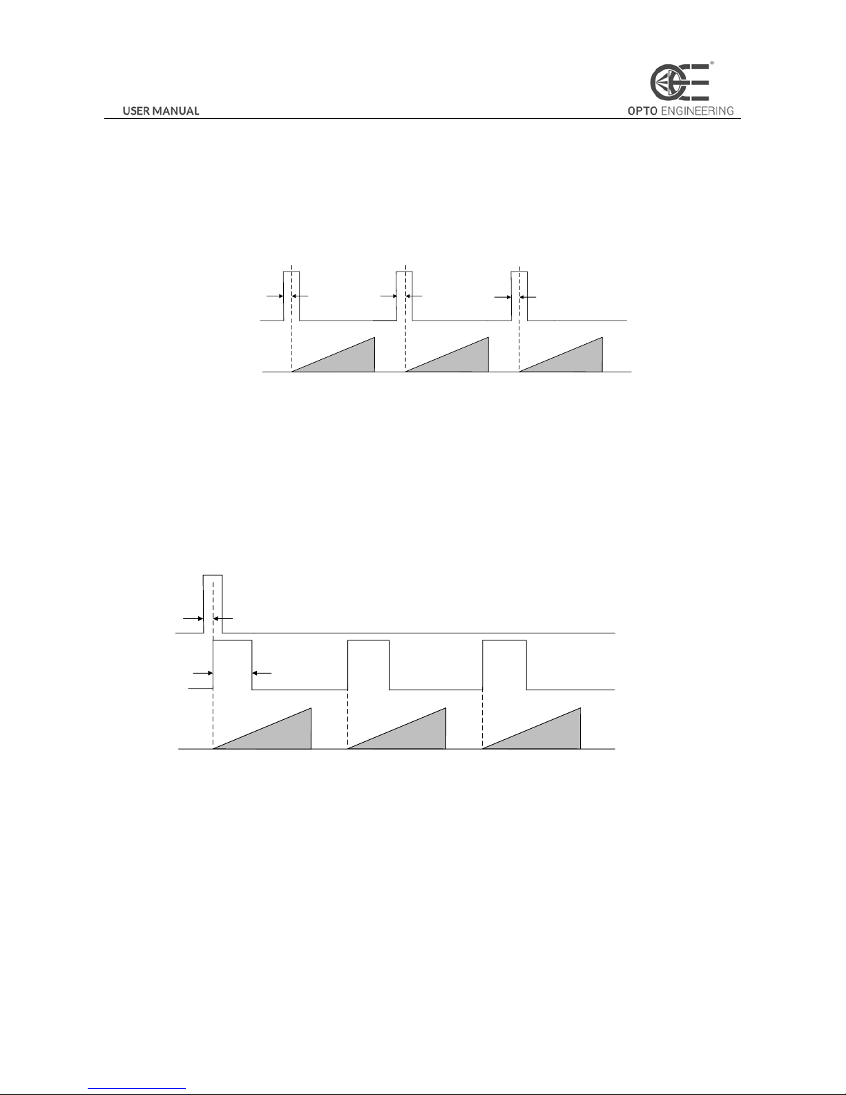
(1) Single frame mode
Expose only once when inputting one trigger signal.
Sensor
exposure
Intergration1 Intergration2 Intergration3
Trigger_in1
Trigger
delay
Trigger_in2
Trigger
delay
Trigger_in3
Trigger
delay
Figure 3-16 Single Frame Mode
The frame rate and exposure time decide to trigger the next frame or not when reading out camera data. If exposure is in
progress, the camera will ignore another external trigger signal. You can set a longer exposure time to achieve Bulb Shutter.
(2) Burst mode
The camera supports burst mode: receiving one trigger signal and outputting multiply frames images. You can set the burst
number by Acquisition Burst Frame Count in the client software. The range is from 0 to 1023. The sequence map is shown in
Figure 3-17. If Burst Frame Count = 3, one trigger signal will output three frames images and at the same time output three
strobe signals.
Strobe
Trigger_in1
Sensor
exposure
Intergration1 Intergration2 Intergration3
Trigger
delay
Duration
Figure 3-17 Burst Mode Sequence Map
(3) PWM mode
Support PWM mode. The difference in the sensor’s exposure time is the main difference between the PWM mode and the
single frame mode. In the PWM mode, the duration of trigger source decides the sensor’s exposure time of each frame. The
sequence map is shown in Figure 3-18.
Page 24
23
Strobe
Trigger_in1
Sensor
exposure
Intergration1 Intergration2
Intergration3
Trigger
delay
Trigger_in2
Trigger_in3
Duration
Trigger
delay
Trigger
delay
Figure 3-18 PWM Mode Sequence Map
3.6 Counter Control
The counter can divide frequencies that from external inputting trigger signal. You can control the exposure depends on your
expectations. Operation steps are as follows:
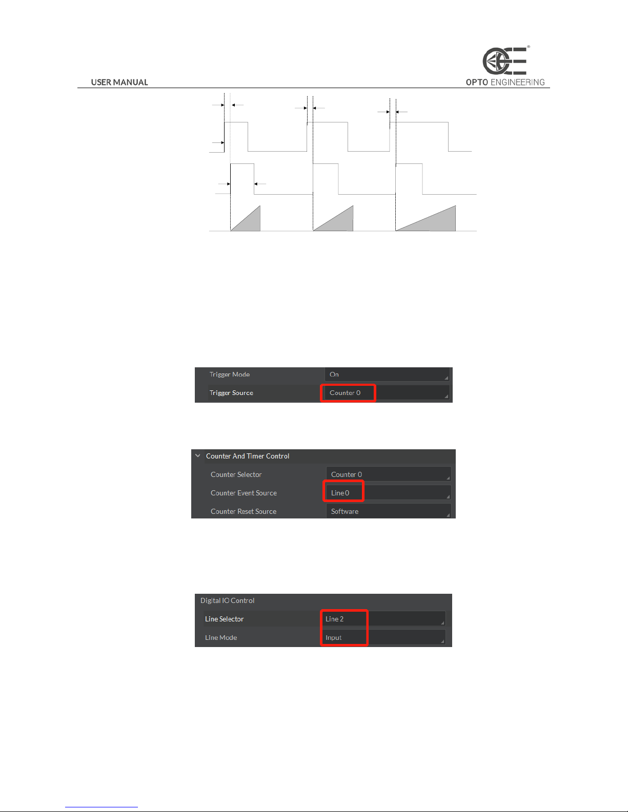
As shown in Figure 3-19, click Acquisition Burst Frame Count and select Trigger Source. Choose Counter 0.
Figure 3-19 Trigger Source Configuration
As shown in Figure 3-20, click Counter And Timer Control and select external trigger source which needs frequency division.
Figure 3-20 Counter Frequency Division Configuration
Note:
By default, Line 0 is signal input pin. Line 2 is configurable input and output pin. Configure Line 2 to input pin in Digital IO
Control, as shown in Figure 3-21, in order to do frequency division for Line 2.
Figure 3-21 Configuring Line 2 Pin to Input
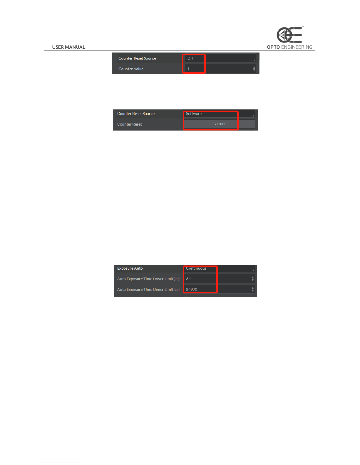
In Counter And Timer Control, you should set Counter Value. Parameter value range is from 1 to 1023. Please see the red 2 in
Figure 3-22.
Page 25
24
Figure 3-22 Counter Parameter Setting
By default, Counter Reset Source is OFF as shown in the red 1 in Figure 3-22. Click Counter And Timer Control and select
Counter Reset Source. Choose Software and click Execute to reset the counter, as shown in Figure 3-23.
Figure 3-23 Resetting The Counter
3.7 Imaging Parameter Setting
3.7.1 Exposure Time
Please refer to the camera technical index to acquire the supported exposure time. The exposure control supports manual
mode, single mode and continuous mode. When setting trigger mode, the single mode and continuous mode are invalid.
When setting single mode or continuous mode, the exposure time will be limited by Auto Exposure Time Lower Limit and
Auto Exposure Time Upper Limit. The time range should only be set between Auto Exposure Time Lower Limit and Auto
Exposure Time Upper Limit.
Click Acquisition Control in the attribute list. Select Auto Exposure Time Lower Limit and Auto Exposure Time Upper Limit.
Input available parameter to the numeric field. Set the running parameter range of the auto exposure time, as shown in Figure
3-24.
Figure 3-24 Exposure Control
3.7.2 Gain Control
Please refer to the camera technical index to acquire the supported Gain Value. Gain Control supports manual mode, single
mode and continuous mode. Gain Control under these three modes can be shown as follows:
Manual mode: Set Gain according to the user’s setting value.
Single mode: Set Gain value automatically according to the target image brightness. Set once only.
Continuous mode: Adjusting Gain continuously according to the target image brightness.
When setting single mode or continuous mode, Gain is limited by Auto Gain Lower Limit and Auto Gain Upper Limit. Gain
Range should only be set between Auto Gain Lower Limit and Auto Gain Upper Limit.
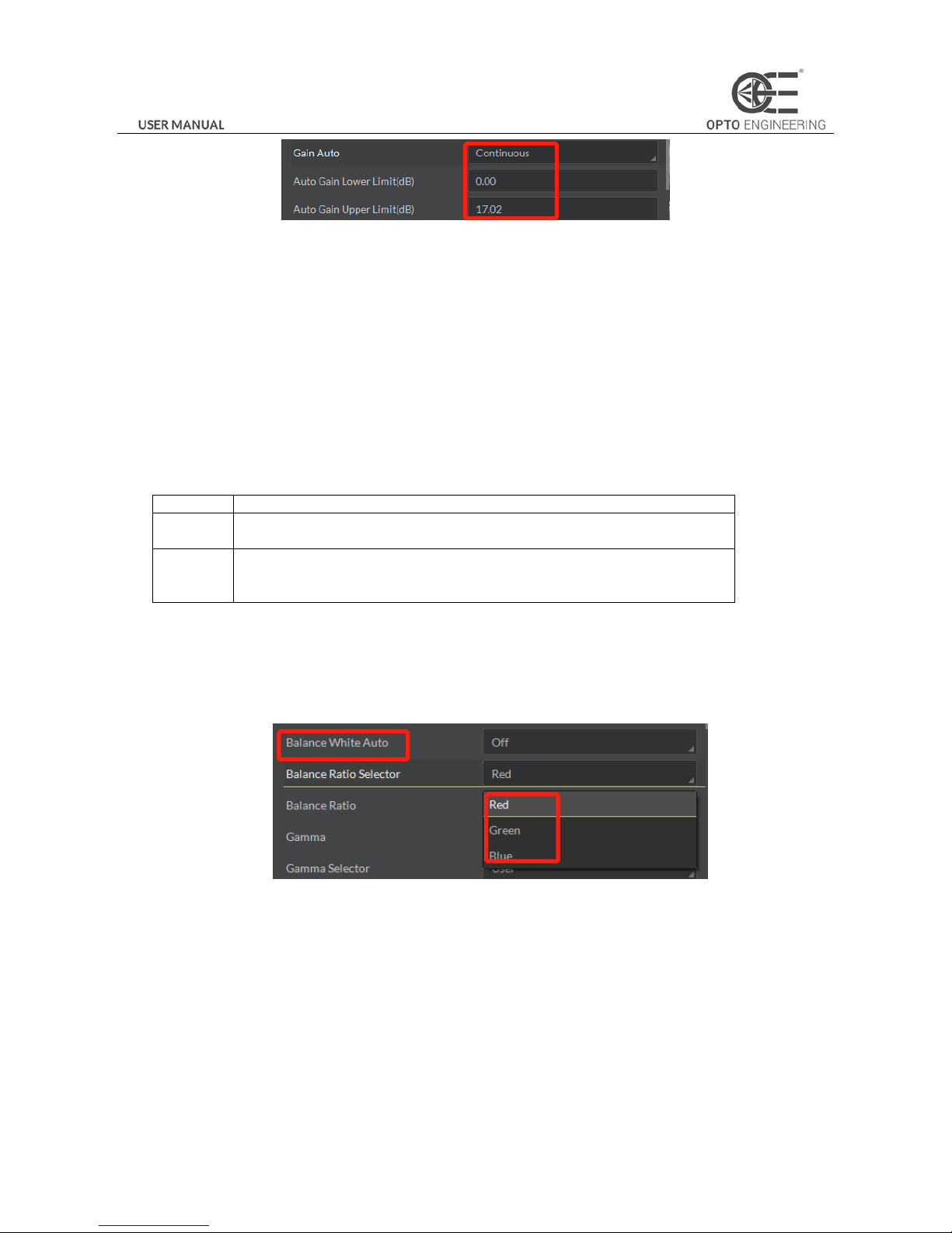
Click Analog Control in the attribute list. Click Gain Auto. Select Gain Mode. Input available parameter in the numeric field
and finish setting, as shown in Figure 3-25.
Page 26
25
Figure 3-25 Gain Control
The noise increases when Gain increases. Auto exposure and Auto Gain are mutually restricted. When the image is dark, the
camera will firstly increase the exposure time. Secondly, the camera starts to adjust Gain Value when the exposure time turns
to the maximum. When the image is bright, the camera will firstly decrease Gain Value. Secondly, it starts to adjust the
exposure time when Gain Value turns to the minimum.
3.7.3 White balance
The camera supports the white balance. The white balance refers to the camera color adjustment depending on different
light sources. Adjust the Gain Value of the image’s R channel and B channel to keep white regions white under different color
temperatures. Ideally, the proportion of R channel, G channel and B channel in the white region is 1:1:1.
Table 3-1 White Balance Status Introduction
Status
Description
OFF
MBW mode: You can adjust the R, G, and B gain value manully. The adjustable range
is 1 to 4095, 1024 means the ratio is 1.0 .
ONCE
Adjust the white balance value according to the current scene and the adjustment
stops automatically after a while. The adjustment adopts a algrithm that looks for the
gray blocks in the Bayer data.
Note:
The white balance adjustment is only available in color models.
Click Analog Control in the attribute list. Click Balance White Auto and Balance Ratio Selector. Select available white balance
status parameter and finish setting, as shown in Figure 3-26.
Figure 3-26 White Balance Setting
3.7.4 Area Setting of Auto Functions
The camera can adjust exposure time and white balance automatically to achieve your expectations. By default, the camera
will adjust the brightness and the white balance of the whole image. In addition, you can also set an area of interest, which is
called AOI. The camera will adjust the AOI in the image. And the area outside the selected region will also be changed.
Regional exposure and regional white balance are generally used in the back light scene and the scene with the great
difference of regional brightness. You can also select rectangle region. The camera will adjust the region’s exposure and white
balance to achieve the best image quality.
Page 27
26
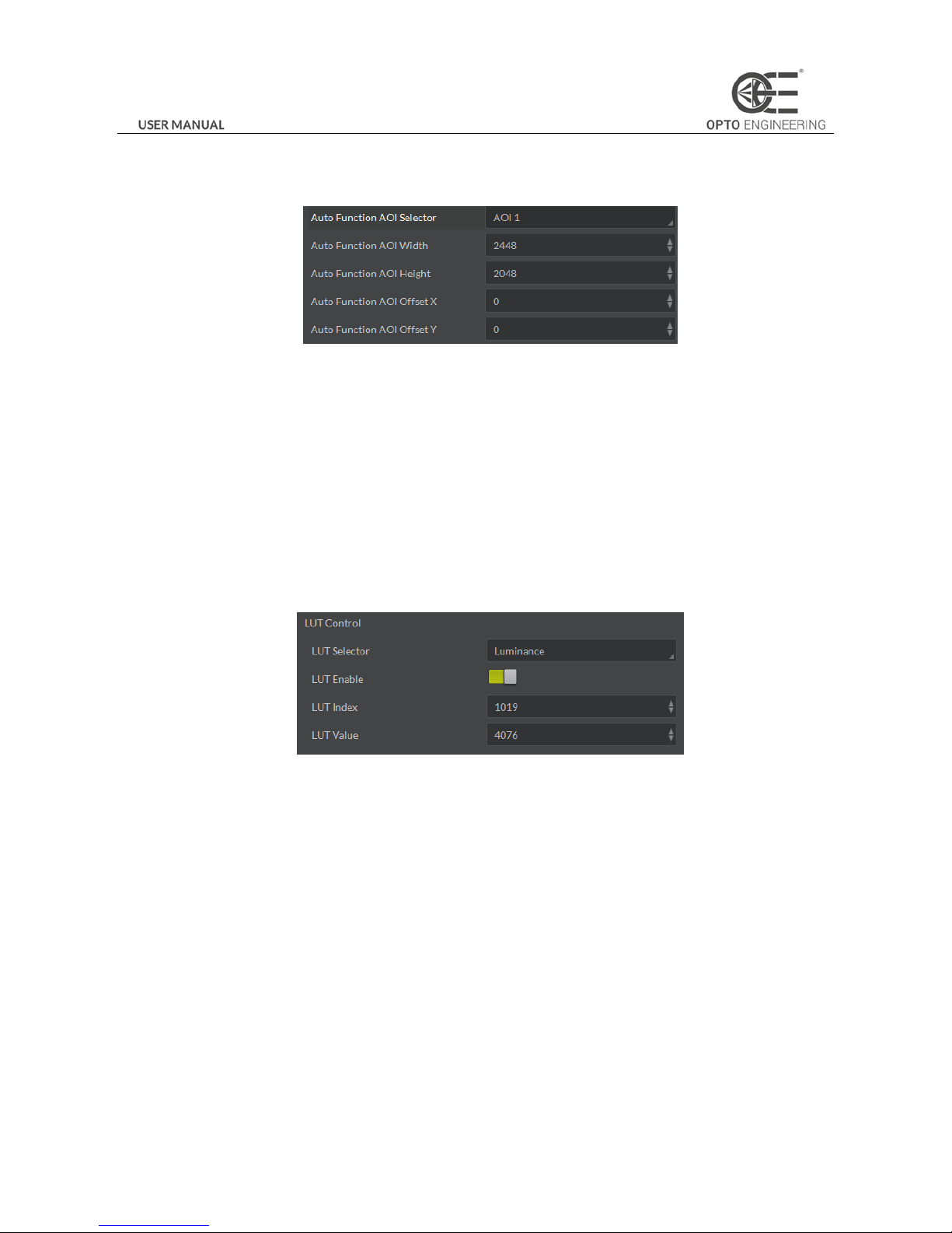
Click Analog Control in the attribute list. Select Auto Function AOI Selector. Choose AOI1 or AOI2. Adjust Auto Function AOI
Width value and Auto Function AOI Height value and finish setting, as shown in Figure 3-27.
Figure 3-27 AOI Setting
Note
:
The available exposure region and the white balance region are the overlapped part of the setting region and the image
region. If there is no overlap, the available region refers to the whole image.
3.7.5 Look Up Table (LUT)
LUT is the grey level mapping table. You can change the grey level in your interested regions. The operation can be linearity
curve or custom mapping curve. LUT and Gamma are mutually exclusive.
Set the user mode to Guru Mode. Click LUT Enable and adjust the parameters, as shown in Figure 3-28.
Figure 3-28 LUT Setting
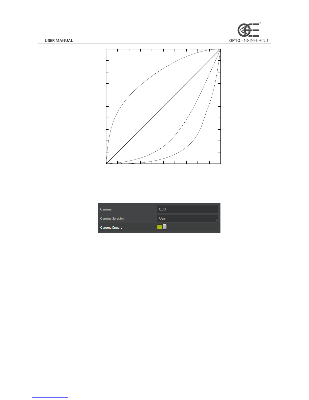
3.7.6 Gamma Correction
The camera supports Gamma Correction. Normally, the output of the camera chip and the number of photon that the sensor
(on the chip) received are linear. And Gamma Correction provides a non-linear output. If the Gamma value is between 0.5 and
1, the image brightness decreases while the brightness of the dark area increases. If the Gamma value is between 1 and 4, the
image brightness increases while the brightness of the dark area decreases.
Page 28
27
1
0.9
0.8
0.7
0.6
0.5
0.4
0.3
0.2
0
1
0.90.80.70.6
0.50.40.3
0.2
0
0.1
0.1
Gamma=1
Gamma=0.5
Gamma=2
Gamma=4
Figure 3-29 Gamma Curve
Click Analog Control in the attribute list. Select Gamma and Gamma Selector and set the parameter as shown in Figure 3-30.
Figure 3-30 Gamma Setting
Note:
Different cameras versions have different default function parameters. The figures shown above are only for reference.
3.7.7 Brightness, Hue and Saturation
Brightness
You can adjust the brightness of the exposure target. The default value is 64. The larger the value, the brighter the image.
Hue
You can adjust the hue value in HSV. The default value is 128.
Saturation
You can adjust the saturation value in HSV. The default value is 128. The larger the value, the higher the saturation and the
stronger the color.
Note:
The hue and the saturation are only for the color camera.
Page 29
28
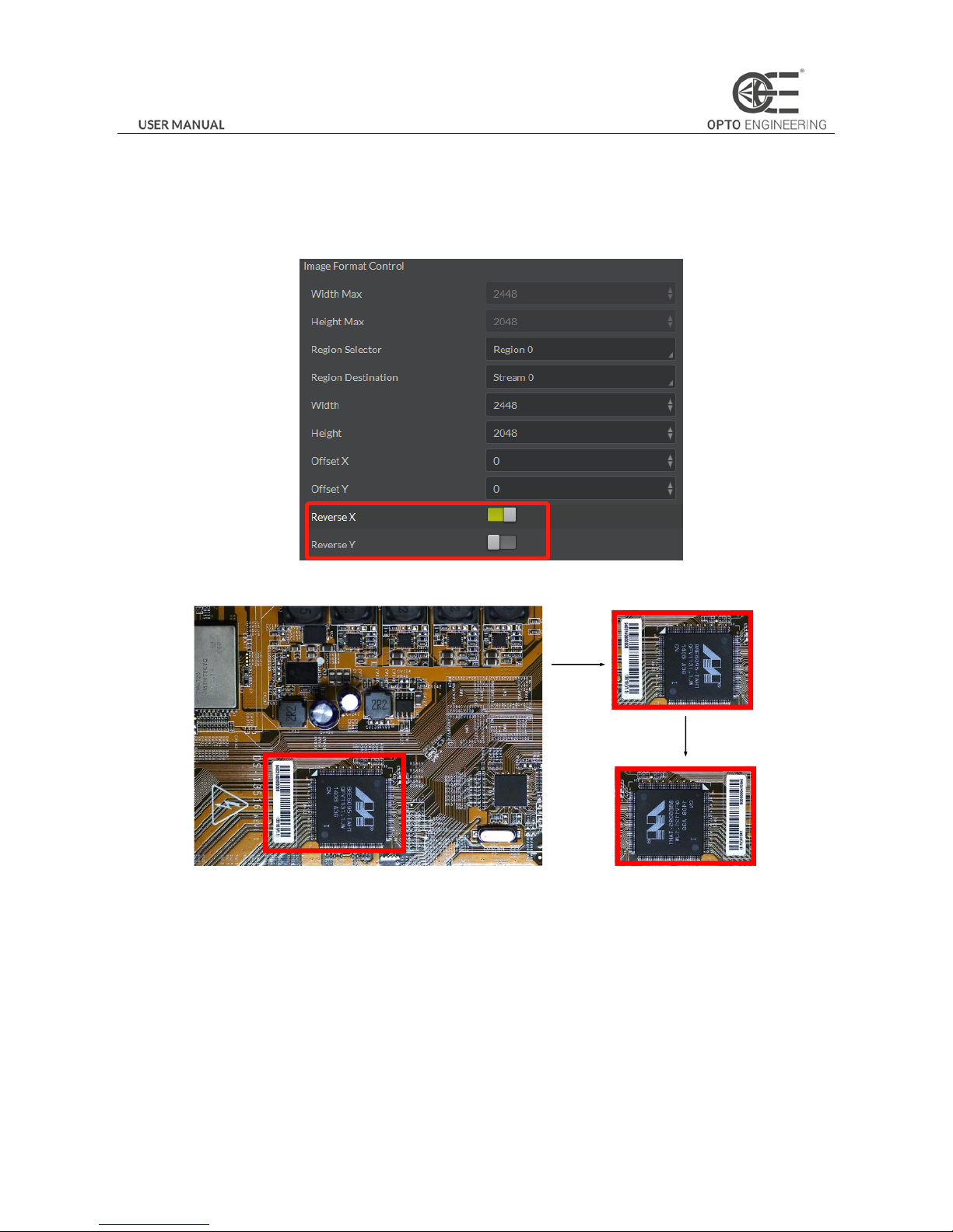
3.7.8 Image Reverse
The camera supports image horizontal mirroring. Open the mirroring function to gain the horizontal mirroring image. Click
Image Format Control. Tick Reverse X (horizontal) or Reverse Y (vertical) according to your preference, as shown in Figure
3-31.
Figure 3-31 Tick Mirroring Function
AOI
Output
Reverse
(horizontal)
Figure 3-32 The Comparison of ROI Output Before And After Mirroring
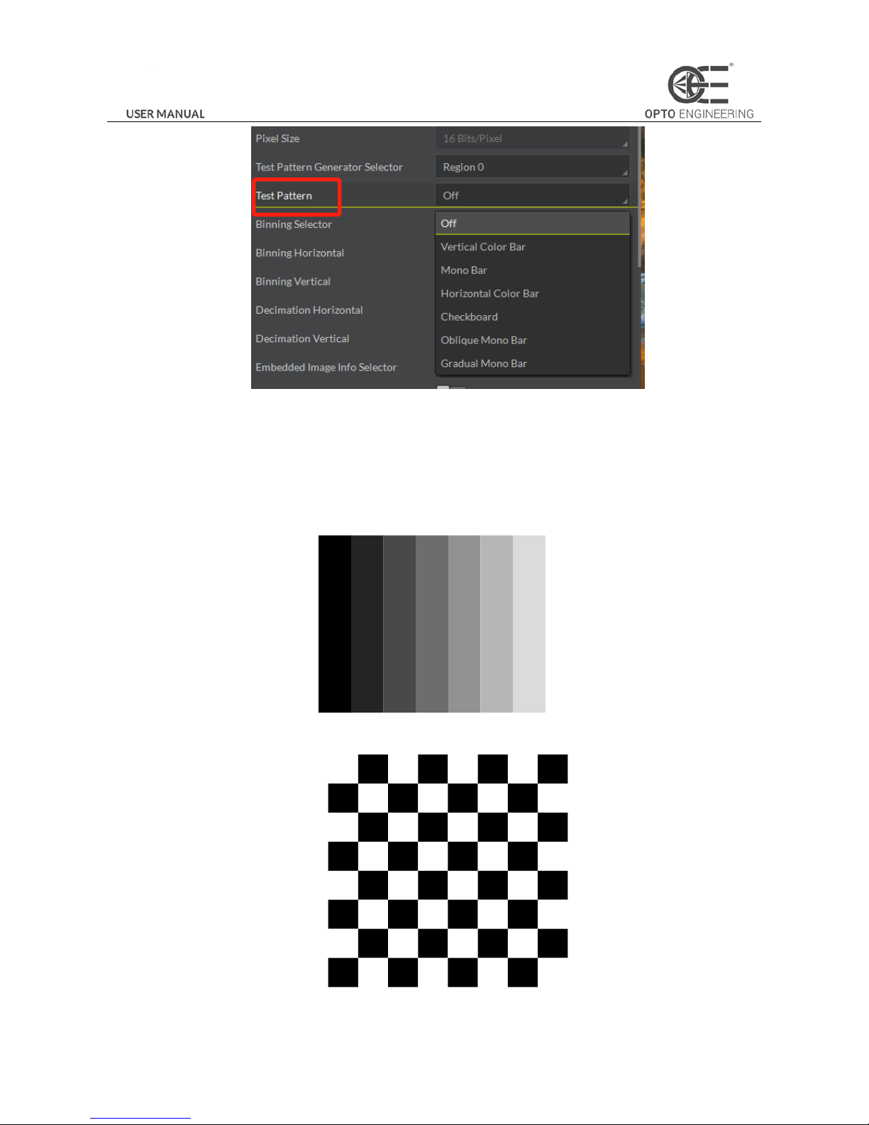
3.7.9 Test pattern
Click Image Format Control in the attribute list. Select Test Pattern and set the parameter. The default test pattern is OFF, as
shown in Figure 3-33.
Page 30
29
Figure 3-33 Test Pattern
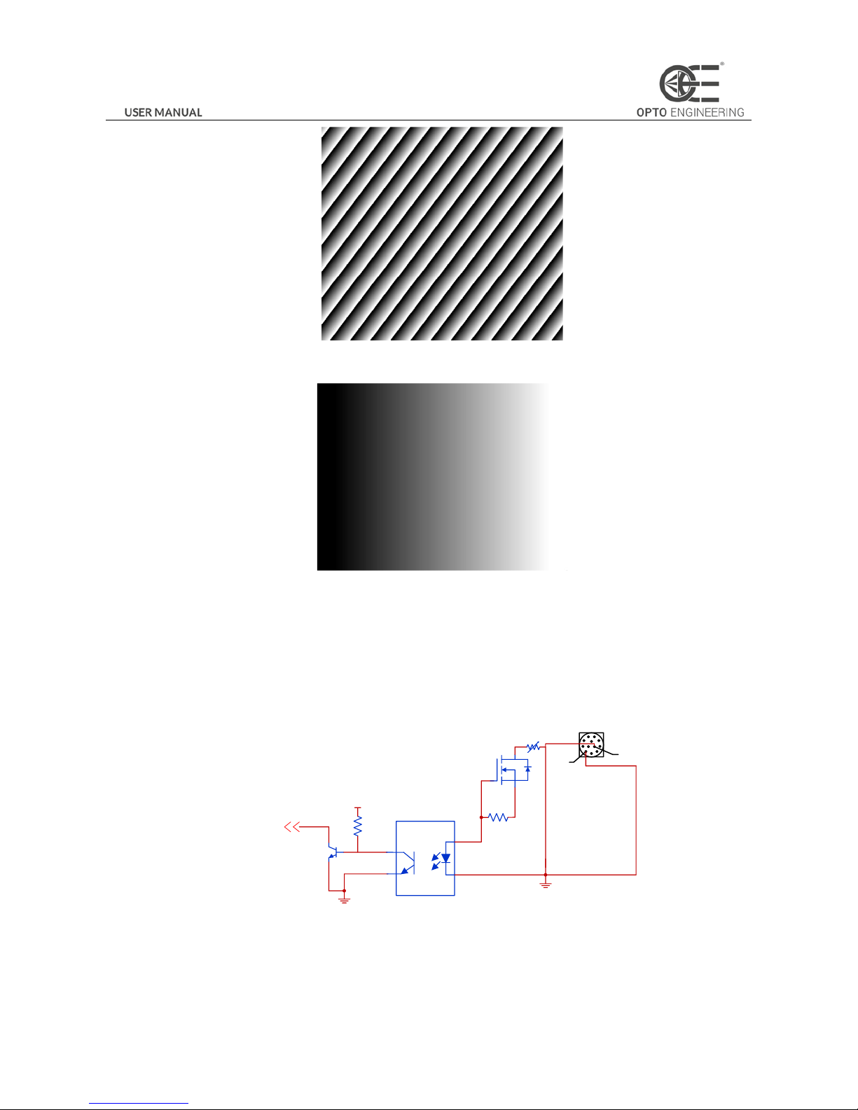
The camera provides four test patterns, including Mono Bar, Checkboard, Oblique Mono Bar, and Gradual Mono Bar as
shown in the following four figures.
Note:
Color camera and black and white camera have different test patterns. The specific test pattern is decided by the camera
function.
Figure 3-34 Mono Bar Test Pattern
Figure 3-35 Checkboard Test Pattern
Page 31
30
Figure 3-36 Oblique Mono Bar Test Pattern
Figure 3-37 Gradual Mono Bar Test Pattern
3.8 I/O Electric Feature
3.8.1 Line0 Opto-isolated Input Circuit
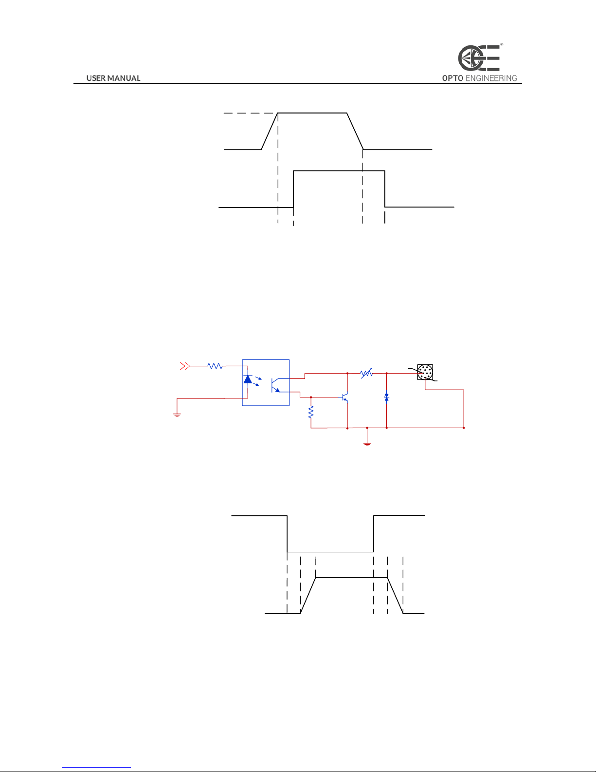
In controlling camera I/O, Line0 input circuit can be shown in Figure 3-38.
IO_IN0
4
12
2.5V_IO
GND_IO
Figure 3-38 Input Circuit
Logic 0 input level: 0 to 1 VDC (OPTO_IN pin)
Logic 1 input level: 1.5 to 24 VDC (OPTO_IN pin)
Maximum input current: 25 mA
Page 32
31
Please make sure the input voltage is not from 1V to 1.5V as the electric status among the two values is not stable.
Logic 1
Input Level
Logic 0
Input Level
Internal Logic
TDR TDF
Figure 3-39 Input Logic Level
Input rising delay (TDR): 2.6μs
Input falling delay (TDR): 19.2μs
3.8.2 Line1 Opto-isolated Output Circuit
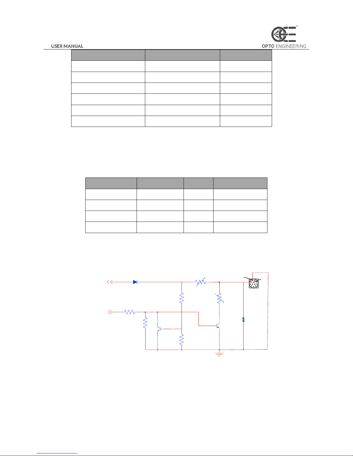
In controlling I/O, Line1 output circuit can be shown in Figure 3-40.
5
11
IO_OUT0
GND_IO
Figure 3-40 Output Circuit
Maximum Line1 output current: 25 mA
Logic 1
Output Level
Logic 0
Output Level
Internal
Logic
TDR TDF TFTR
Figure 3-41 Output Logic Level
Opto-isolated output electric feature can be shown in Table 3-2 (The external voltage is 3.3 V and the external resistance is 1
K.)
Table 3-2 Output Electric Feature
Page 33
32
Parameter
Symbol
Value
Output Logic Low Level
VL
575mV
Output Logic High Level
VH
3.3V
Output Rising Time
TR
8.4us
Output Falling Time
TF
1.9us
Output Rising Delay
TDR
16.6us
Output Falling Delay
TDF
3.6us
Table 3-6 shows the corresponding current and the parameter of output logic low level when the opto-isolated outputs the
different external voltage and resistance.
Table 3-3 The Parameter of Output Logic Low Level
External Voltage
External Resistor
VL
Output Current
3.3V
1KΩ
575mV
2.7mA
5V
1KΩ
840mV
4.1mA
12V
2.4KΩ
915mV
4.6mA
24V
4.7KΩ
975mV
4.9mA
3.8.3 Line2 Configurable Bi-direction I/O Circuit
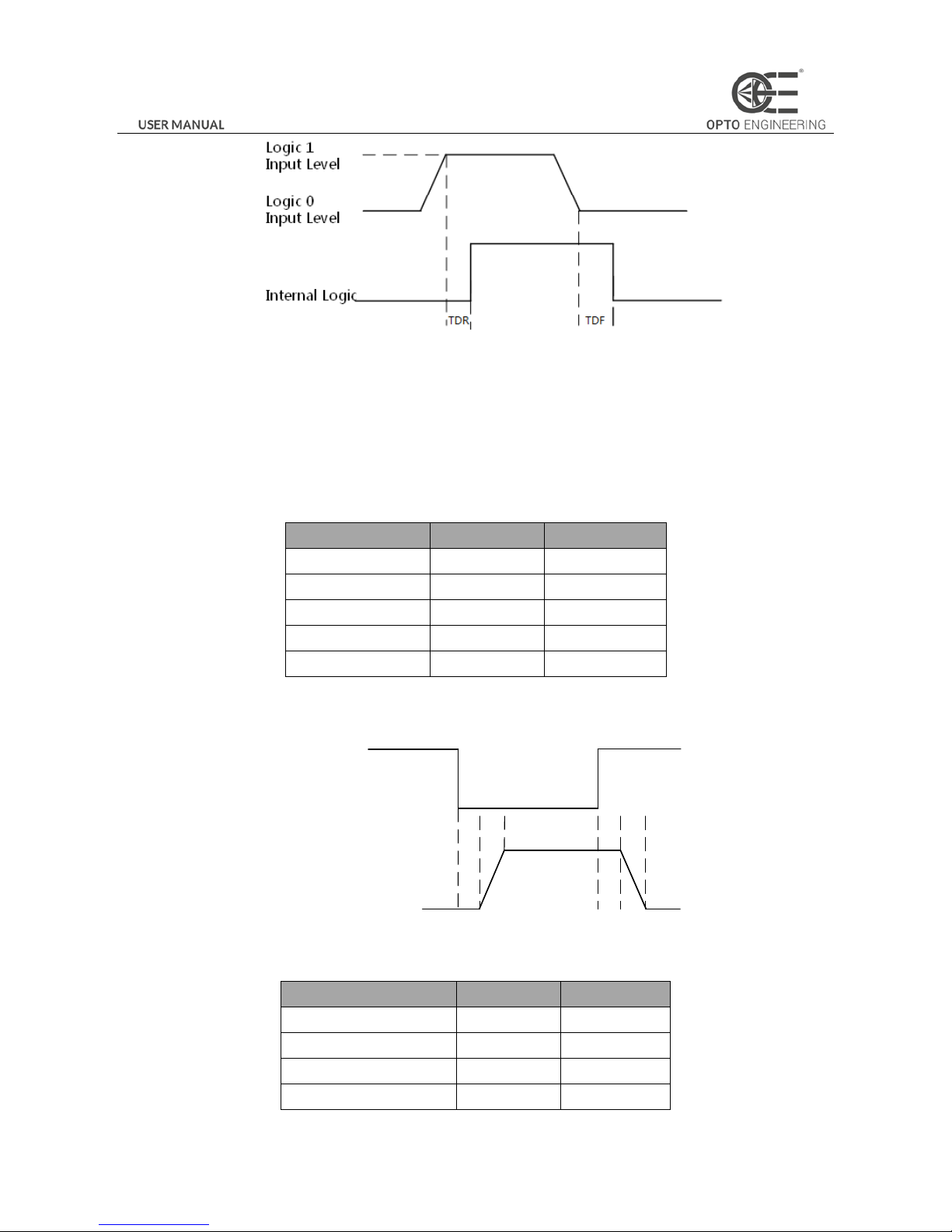
In controlling I/O, the configurable bi-direction non-isolated IO circuit of Line2 can be shown in Figure 3-42.
10
1
GPI2
GPO2
Figure 3-42 Line2 Bi-direction I/O Circuit
1. Configure Line2 to input pin
Logic 0 input level: 0 to 0.5 VDC (GPIO2 pin)
Logic 1 input level: 1.5 to 30 VDC (GPIO2 pin)
Please make sure the input voltage is not from 0.5V to 1.5V as the electric status among the two values is not stable.
Page 34
33
Figure 3-43 Inputting Logic Level
Please connect to GND pin first to protect GPIO pin and then input voltage to Line2 pin.
2. Configure Line2 to output pin
The available maximum current is 25 mA and the output impedance is 40 Ω .
When the environment temperature is 25 degree centigrade, the relationship among external voltage, impedance and the
output low level can be shown in Table 3-4.
Table 3-4 The Parameter of Output Logic Low Level
External Voltage
External Resistor
VL(GPIO2)
3.3V
1KΩ
160mV
5V
1KΩ
220mV
12V
1KΩ
460mV
24V
1KΩ
860mV
30V
1KΩ
970mV
When the external voltage of 1KΩ external resistance turns to 5V, features of output logic level and electric feature in
GPIO2 configuration can be shown in Figure 3-44 and Table 3-5.
Logic 1
Output Level
Logic 0
Output Level
Internal
Logic
TDR TDF TFTR
Figure 3-44 Output Logic Level
Table 3-5 Output Electric Feature
Parameter
Symbol
Value
Output Logic Low Level
TR
0.06us
Output Logic High Level
TF
0.016us
Output Rising Time
TDR
0.03us
Output Falling Time
TDF
0.28us
Page 35
34
3.8.4 RS-485
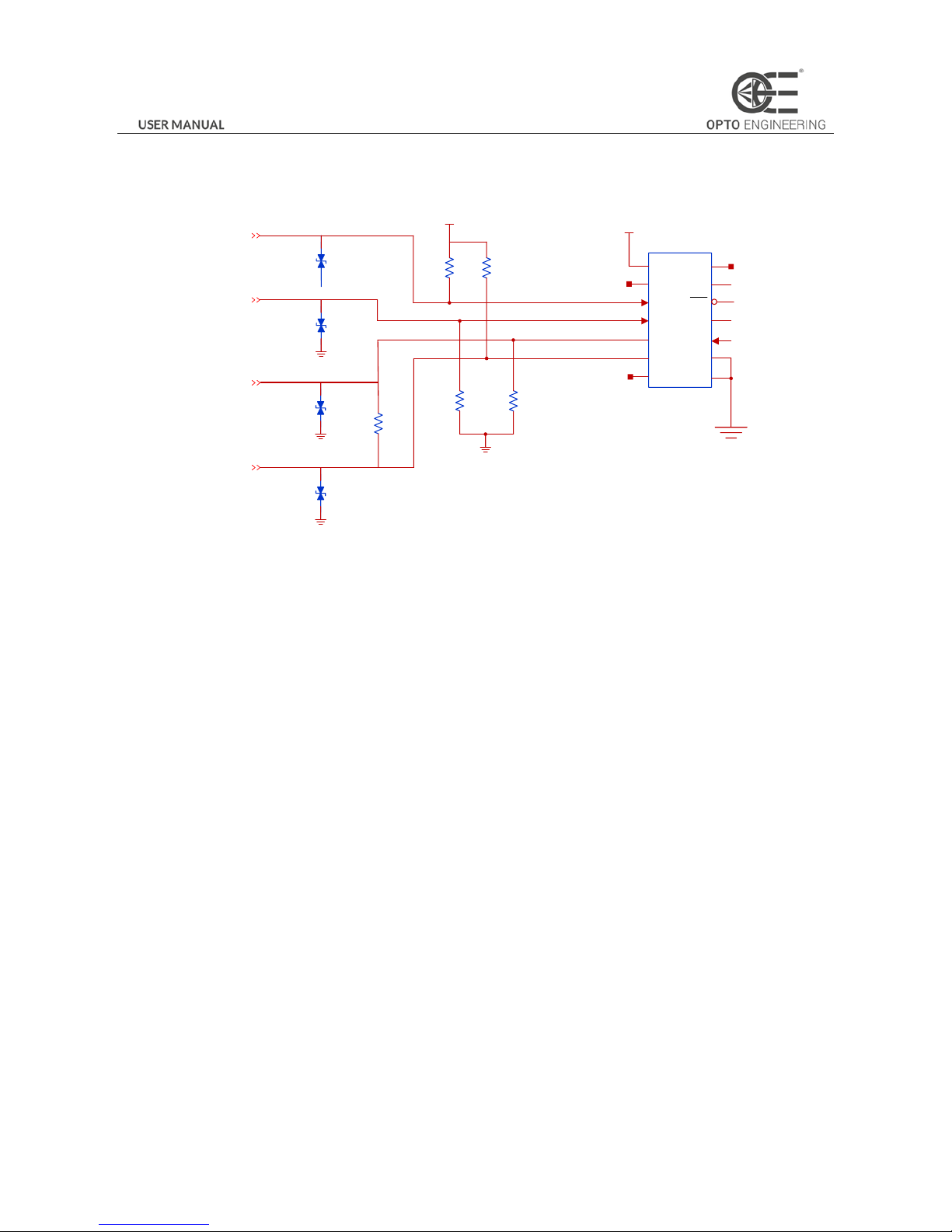
The camera contains a full duplex RS485 interface, and the circuit shown as the figure below:
RS485+
RS485-
5V
VCC
NC3
RX+
RXTXTX+
NC2
NC1
RXD
RE
TE
TXD
GND
GND
5V
RS485-
RS485+
Figure 3-45 RS-485 Circuit
3.9 Transport Layer Control
3.9.1 DHCP and Persistent IP
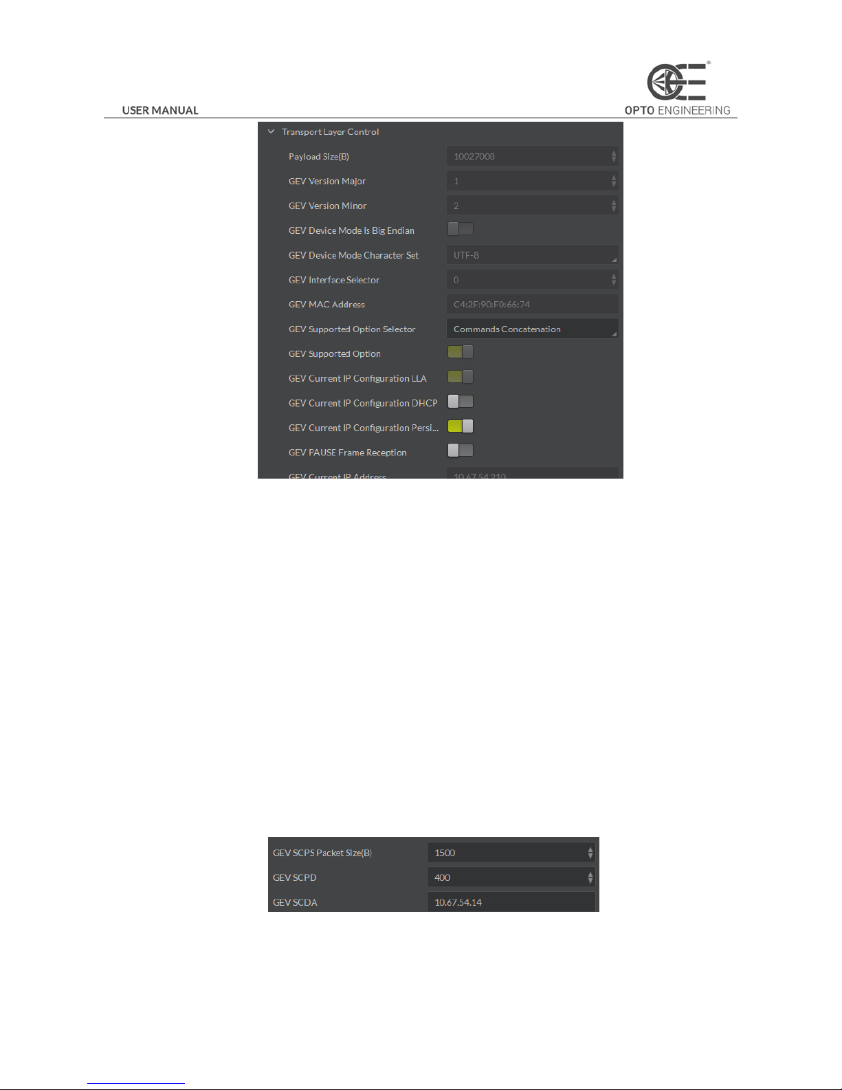
The camera supports connecting with PC through DHCP or Persistent IP. As shown in Figure 3-46, the camera will acquire IP
according to the following order.
(1) If the camera’s Persistent IP is available and the configured Persistent IP is available, the camera will load this
Persistent IP. Or execute (2).
(2) If DHCP function is available and the acquired IP address is available, the camera will load IP address that acquired
by DHCP. Or execute (3).
(3) Acquire LLA.
Page 36
35
Figure 3-46 The Transport Layer Control Interface
3.9.2 Efficient Bandwidth and Setting
Packet Size and Packet Delay control the 1000M Ethernet’s actual bandwidth. The theoretical calculation of 1000M network
port’s image loading bandwidth is:
BandWidth=((PacketSize–(IP+UDP+GVSP Header))/(PacketSize + MACHeader+ CRC+ Packet-Delay)) * 1000M/bps.
Normally, IP/UDP/GVSP Header takes 36 bytes. MAC Header takes 14 bytes. CRC takes 4 bytes. Taking setting Packet Size
1500 and Packet Delay 400 as an example, the actual network bandwidth is
BandWidth=(1500-36)/(1500+14+4+400)*1000Mbps=759.36 Mbps
The actual network bandwidth is smaller than the theoretical one because of the network message, GVCP, GCSP leader,
Trailer and any other overheads.
Set Packet Size (GEV SCPS Packet Size) value and Packet Delay (GEV SCPD) value by using the slider and the input box. You
can set these two parameters according to the computer performance and the network card performance in the condition of
no data package loss, as shown in Figure 3-47.
Figure 3-47 Packet Size Setting And Packet Delay Setting
Page 37
36
3.10 User Parameter and Preference Setting
3.10.1 Parameters Saving and Loading
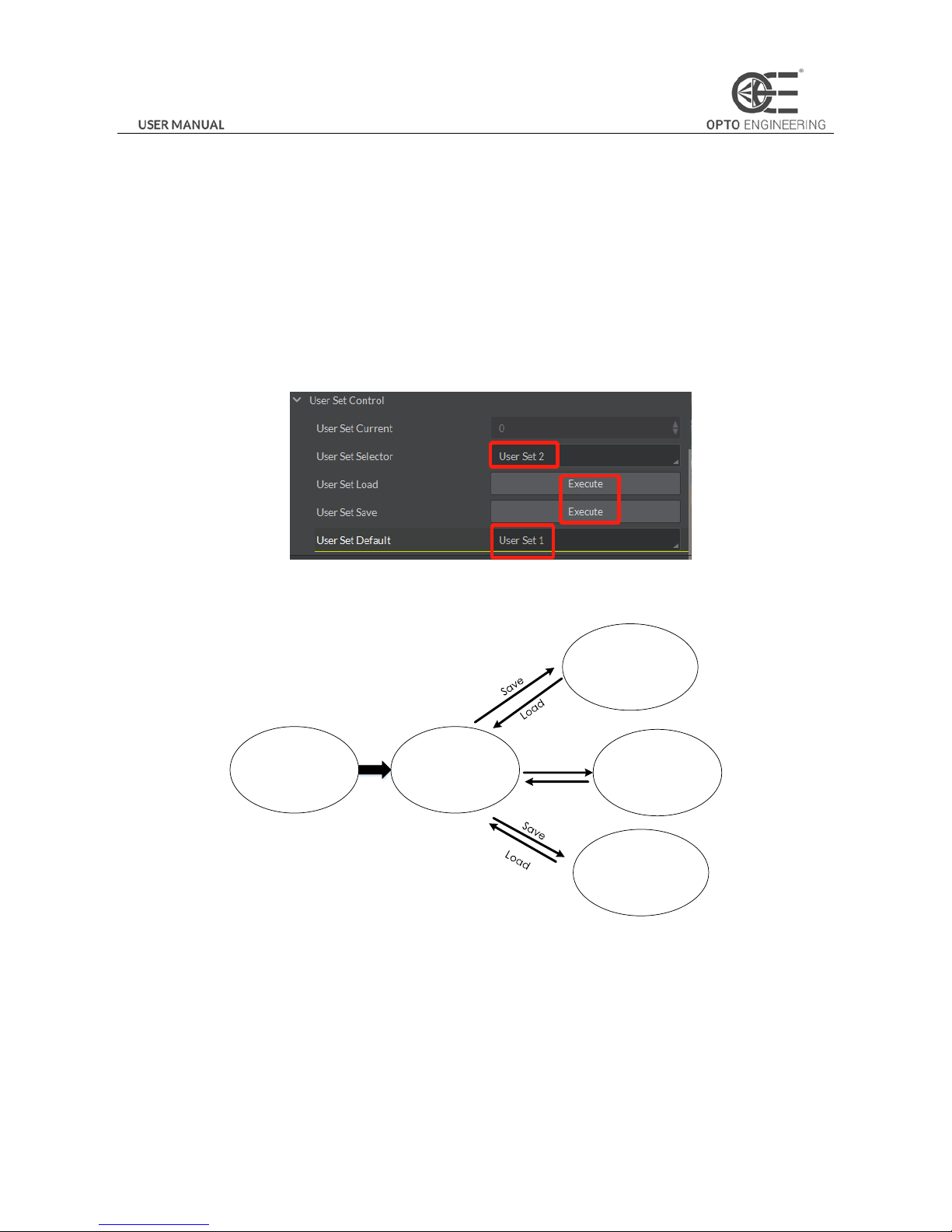
The camera can save four groups of parameters, including one group of factory parameter and three groups of configurable
parameters. You can save currently configured parameter and set corresponding default parameter when logging in at next
time in User Set Control in the attribute list.
Configuration method: select one of the parameter names in the drop-down box in User Set Selector. Save current parameter
settings. In the drop-down box of User Set Default, select one of the parameters when the client runs, as shown in Figure
3-48. Click Execute in both User Set Save and User Set Load.
Figure 3-48 Parameters Saving And Loading
Figure 3-49 shows the relationship among four groups of parameters.
Currently
Configured
Parameter
User Parameter 1
Unser
Parameter 2
User Parameter 3
Default
Parameter
Load
Save
Load
Figure 3-49 The Relationship Among Four Groups of Parameters
3.10.2 Embedded Information
The camera supports embedded information into the image data. The current supporting embedded information is:
Timestamp
Analog gain
Exposure time
Average brightness
White balance gain
Page 38
37
Frame number
Trigger counter
ROI
The above eight information will be embedded in the image data one by one according to the client sofware. If the
information is not available, it will not be embedded.
The AOI will not affect the embedding. If the region of AOI is small, the first line of the image data is not enough for
embedding. Then the information will be embedded in the second line.
Each embedded information of the available data will be put in the least 8 significant bits (No matter in MONO8 or RGB24).
The Embedded information is as following:
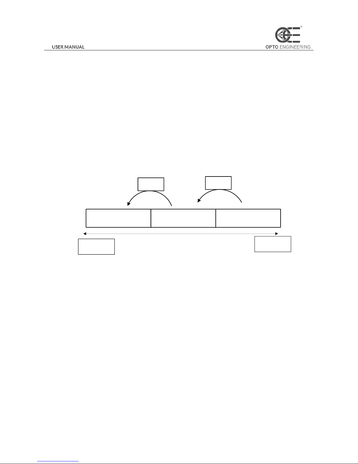
Timestamp: Take four bytes: transmission with four available data.
Data format: The data format of the timestamp is shown in Figure 3-50.
Second_count
5bits
Cycle_count
13bits
Cycle_offset
14bits
125us
intervals
1s
intervals
Least
significant
Most
significant
Figure 3-50 Timestamp Format
Analog gain: Take four bytes: transmission with four available data. Connect the least significant 8 bit of the four data
together.
The data format of analog gain: Show the connected data directly. The range is from 0 to 1023. The Most Significant Bits will
complement 0 automatically.
Exposure time: Take four bytes: transmission with four available data. Connect the least significant 8 bit of the four data
together.
The data format of the exposure time: The connected least significant 8 bit of the four data is the number of the exposure line.
Multiply the line number to 25.8μs. The result is the exposure time. The unit is μs.
Average Brightness: Take four bytes: transmission with four available data. Connect the least significant 8 bit of the four data
together.
The data format of the average brightness: Show the connected data directly. The range is from 0 to 4095. The Most
Significant Bits will complement 0 automatically.
White balance gain: Contains three components of gain. It consumes 8 bytes in total, including two bytes for R channel of
Gain, two bytes for G channel of Gain and four bytes for B channel of Gain. In other words, the transmission uses eight
available image data.
Data format of white balance gain: Each channel consumes 2 bytes. The range is from 0 to 4095.
Frame number: Take four bytes.
Frame number format: Connect four bytes directly. The range is from 0 to 2^32.
Page 39
38
Trigger counter: Take 4 bytes. The range is from 0 to 2^32.
ROI: Take three bytes in the initial position. The length and the width consume three bytes.
The data format of ROI:
(1) The initial position of ROI takes three bytes. The length and the width consume three bytes.
(2) The initial coordinate of ROI’ column takes one and a half bytes. The initial coordinate of ROI’s row takes one and a
half bytes. The column coordinate is in the front of the row coordinate. The coordinate of the length and the width
also consume one and a half bytes respectively.
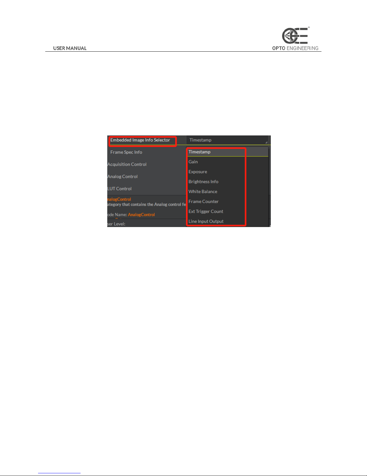
Click Image Format Control in the attribute list. Select Embedded Image Info Selector. Choose the parameter in the
drop-down box and finish setting, as shown in Figure 3-51.
Figure 3-51 Embedded Information
3.11 Firmware Updating
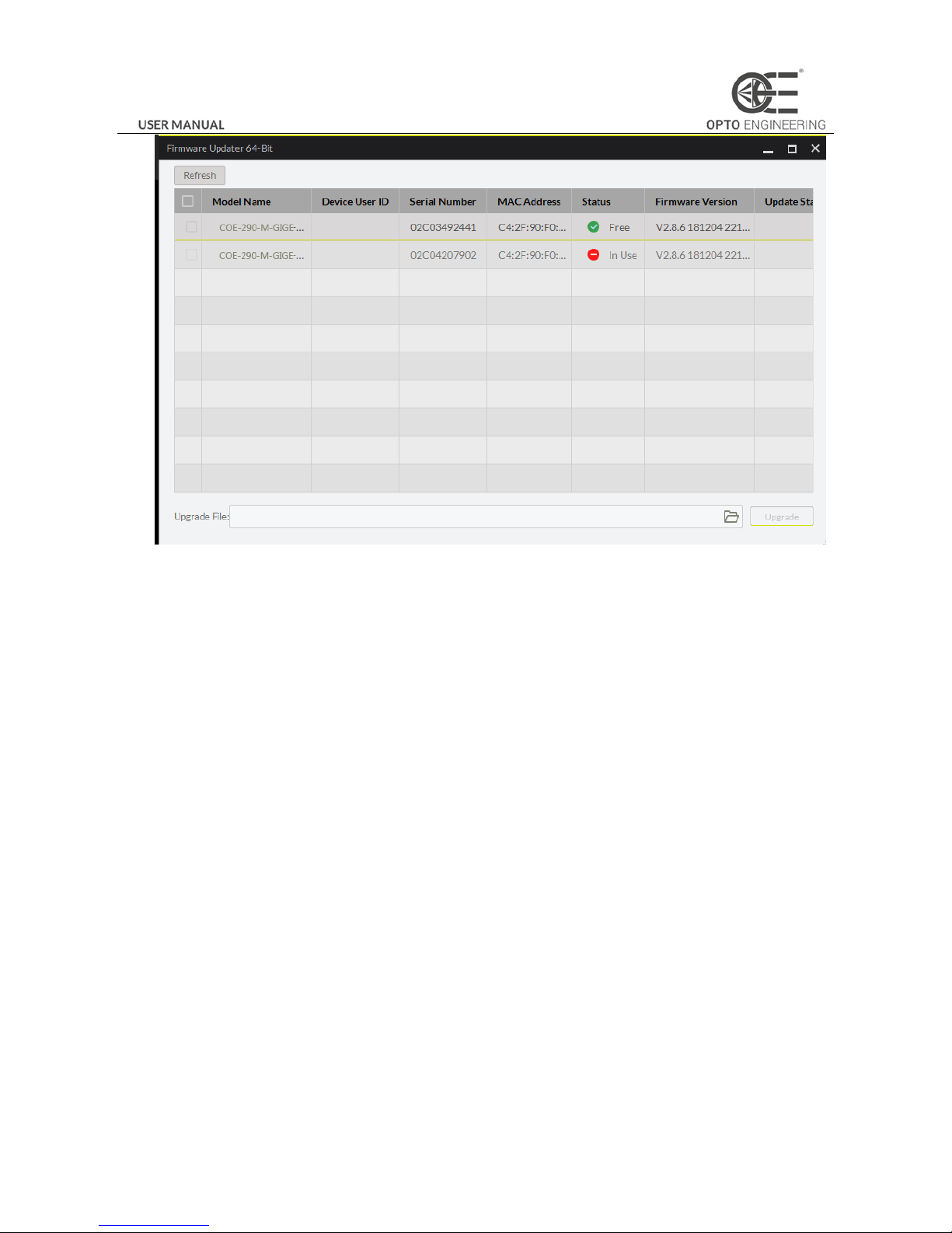
The camera supports firmware updating via LAN. After selecting available device in the device list, open Tool>Firmware
Updating Tool in the Menu. Select available firmware updating kit, as shown in Figure 3-52.
Page 40
39
Figure 3-52 Firmware Update
Page 41
40
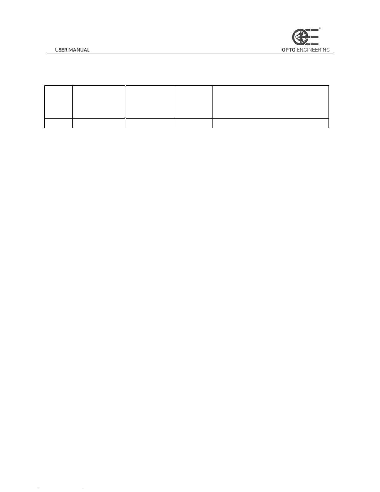
Chapter 4 Revision History
Table 4-1 Revision History Description
Serial
No.
Date Revision Version
Section
No.
Change Description
1
2017-12-01
V1.0.0
—
—
Page 42
41
Chapter 5 Trouble Shooting
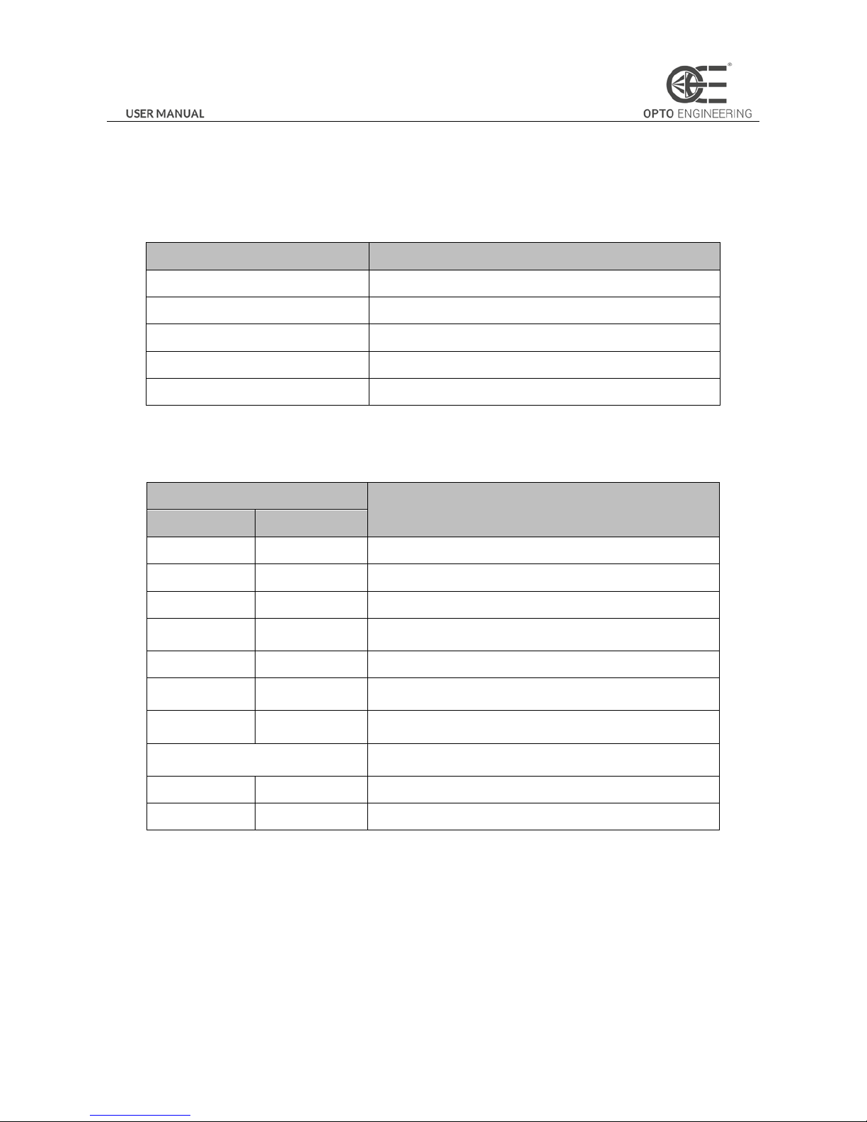
5.1 Indicator Status Definition
Table 5-1 LED Indicator Status
LED Status
Definition
Steady On
The LED indicator keeps lights on all the time
Unlit
The LED indicator keeps unlit all the time
Fast Flicker
The LED indicator flickers every 200ms to 300ms
Slow Flicker
The LED indicator flickers every 1000ms.
Extreme Slow Flicker
The LED indicator flickers every 2000ms.
5.2 Indicator Status Description
Table 5-2 LED Status Description
Indicator Status
Camera Status
Indicator in Red
Indicator in Blue
- - The camera is off or hardware damaged.
-
Steady On
The camera is starting up.
Fast Flicker
-
Uboot loading failed.
Extreme Slow
Flicker
-
IP address confliction or connection error
-
Slow Flicker
Idle while the camera is in the internal trigger mode.
-
Fast Flicker
Transmitting image while the camera is in the internal trigger
mode.
Extreme Slow
Flicker
Transmitting image while the camera is in the external trigger
mode.
The indicator flickers red and blue
alternately evey 1 second.
Upgrading the firmware.
Slow Flicker
-
Camera works normally but is not able to tranmit data.
Steady on
-
Upgrading the firmware failed. Contact the technical support.
Page 43
42
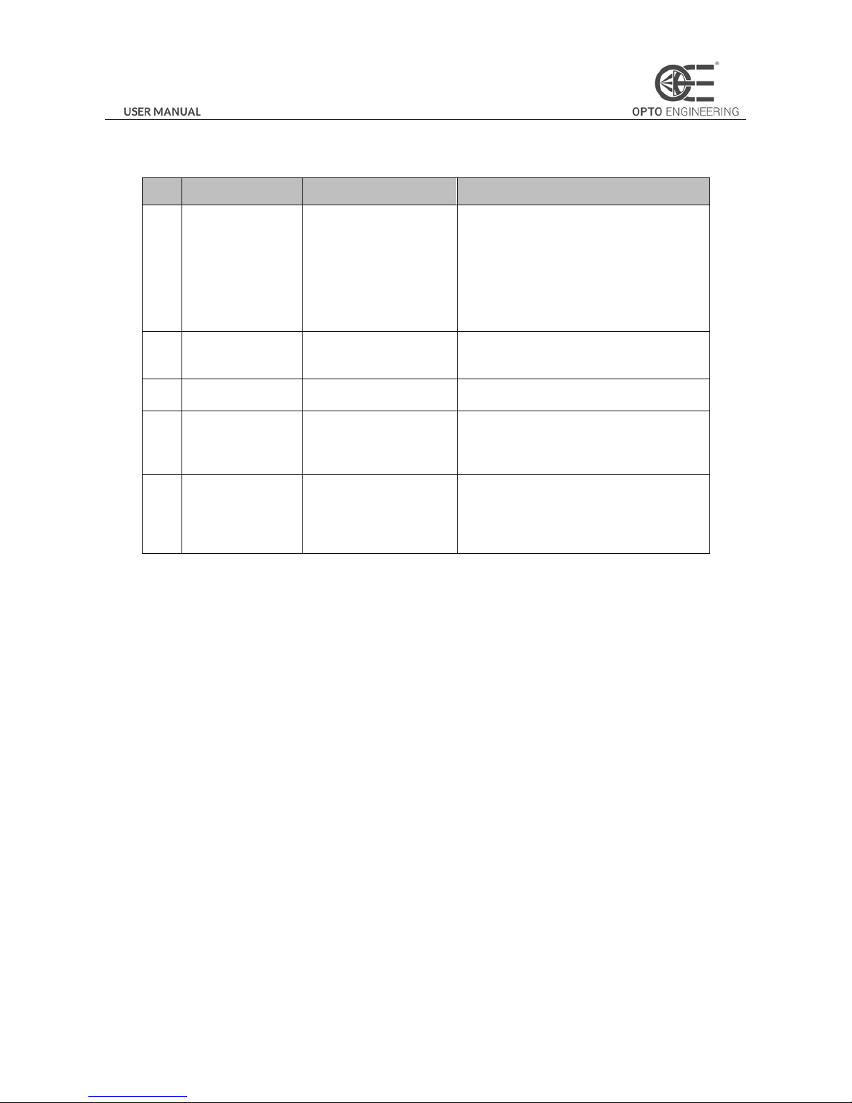
5.3 FAQ
Table 5-3 FAQ
No
Problem Description
Possible Reasons
Solutions
1
1. The camera
cannot be detected
by the client
software.
2. The camera is
detected by the
client software but
connecting failed.
1. The camera does not
work properly.
2. The network cable is
disconected.
3. The camera and the PC
that runs the OECS client
software are not in the
same subnet.
1. Confirm if the power supply of camera is
well connected (via LED indicator), and the
network connects properly (via network
interface indicator).
2. Use OECS IP Configurator to detect the
camera and change the IP address.
3. Confirm if the GenICam and network Filter
driver are installed on the PC.
2
The camera is in
read-only status.
The camera is connected
with another client
software.
Plug out the network cable, and replace it 3
seconds later.
3
The live view of
camera is black.
1. The iris is closed.
2. Camera error
1. Open the iris.
2. Reboot the camera.
4
Camera cannot be
triggered
1. Incorrect cable
connection.
2. The camera works in the
internal trigger mode
Make sure the trigger mode is correct and the
external trigger is well connected.
5
The live view and
image is normal,
while the image
saved could not be
displayed properly.
The image format
mismacthes.
Make sure the image format what you saved is
supported.
Page 44
43
 Loading...