

Page 1
O
D
v
c
SPECIFI
e
i
w
M
2
h
o
a
0
t
N
a
u
O
CATIONS
ANUAL
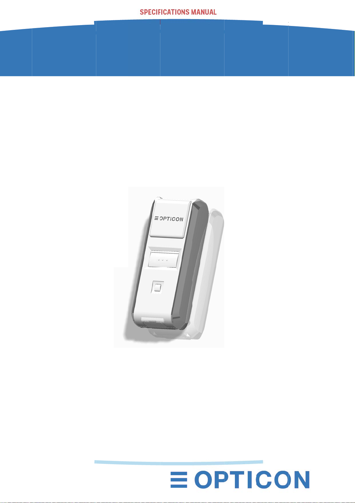
PN-2102i
1st
ata Coll
-
ctor wit
1
Bluetoo
h
2
i
This m
1st
anual pro
data
ides spec
ollector
ifications f
ith laser b
r the OP
rcode sc
-2102i Bl
nner.
etooth
1
Page 2

SPECIFICATIONS MANUAL
OPN-2102i
1st
The information in this document is subject to change without notice.
Document History
Model Number: OPN-2102i Specification Number: SS16056
Edition: 1st Original Spec Number: (SS16017)
Date: 30-September-2016
© 2016 Opticon. All rights reserved.
This manual may not, in whole or in part, be copied, photocopied, reproduced, translated or converted
to any electronic or machine readable form without prior written consent of Opticon.
Limited Warranty and Disclaimers
Please read this manual carefully before installing or using the product.
Serial Number
A serial number appears on all Opticon products. This official registration number is directly related to
the device purchased. Do not remove the serial number from your Opticon device. Removing the
serial number voids the warranty.
Warranty
Unless otherwise agreed in a written contract, all Opticon products are warranted against defects in
materials and workmanship for two years after purchase excluding batteries. Opticon will repair or, at
its option, replace products that are defective in materials or workmanship with proper use during the
warranty period. Opticon is not liable for damages caused by modifications made by a customer. In
such cases, standard repair charges will apply. If a product is returned under warranty and no defect is
found, standard repair charges will apply. Opticon assumes no liability for any direct, indirect,
consequential or incidental damages arising out of use or inability to use both the hardware and
software, even if Opticon has been informed about the possibility of such damages.
Packaging
The packing materials are recyclable. We recommend that you save all packing material to use should
you need to transport your data collector or send it for service. Damage caused by improper
packaging during shipment is not covered by the warranty.
Trademarks
Trademarks used are the property of their respective owners.
Opticon Inc. and Opticon Sensors Europe B.V. are wholly owned subsidiaries of
OPTOELECTRONICS Co., Ltd., 12-17, Tsukagoshi 4-chome, Warabi-shi, Saitama, Japan 335-0002.
TEL +81-(0) 48-446-1183; FAX +81-(0) 48-446-1184
SUPPORT
USA Europe
Phone: 800-636-0090 Phone: +31235692728
Email: [email protected] Email: [email protected]
Web: www.opticonusa.com Web: www.opticon.com
2
Page 3

SPECIFICATIONS MANUAL
Revision History
Product Name : OPN-2102i
Edition Date Page Section Description of Changes
1st 2016/09 /30 - -
OPN-2102i
1st
3
Page 4

SPECIFICATIONS MANUAL
OPN-2102i
1st
Contents
1 Abstract ............................................................................................................................ 6
2 Overview .......................................................................................................................... 6
3 Basic Specifications ....................................................................................................... 7
4 Detailed View ................................................................................................................... 9
5 Electrical Specifications ............................................................................................... 10
5.1 USB ........................................................................................................................................ 10
5.2 Wireless Charging .................................................................................................................. 10
6 Interface Specifications ................................................................................................ 10
6.1 USB Interface ......................................................................................................................... 10
6.1.1 Connector ....................................................................................................................... 10
6.1.2 USB Interface Circuit ...................................................................................................... 10
6.2 Bluetooth ................................................................................................................................ 11
6.3 NFC Tag ................................................................................................................................. 11
7 Optical Specifications ................................................................................................... 11
7.1 Basic Specifications ............................................................................................................... 11
7.2 Laser Scanning Standards ..................................................................................................... 12
7.2.1 Laser Scanning Tilt ......................................................................................................... 12
7.2.2 Laser Scanning Curvature .............................................................................................. 12
8 Technical Specifications .............................................................................................. 13
8.1 Barcode Test Sample ............................................................................................................. 13
8.2 Scan Area and Depth of Field ................................................................................................ 14
8.3 Printed Contrast Signal (PCS) ............................................................................................... 15
8.4 Minimum Resolution ............................................................................................................... 15
8.5 Pitch, Skew and Tilt ................................................................................................................ 15
8.6 Curvature ................................................................................................................................ 16
9 Environmental Specifications ...................................................................................... 16
9.1 Temperature ........................................................................................................................... 16
9.2 Humidity .................................................................................................................................. 16
9.3 Ambient Light Immunity .......................................................................................................... 17
9.4 Dust and Drip Proof ................................................................................................................ 17
9.5 Vibration Strength (without packing) ...................................................................................... 17
9.6 Vibration Strength (in individual packing) ............................................................................... 17
9.7 Drop Impact Strength (without packaging) ............................................................................. 18
9.8 Drop Impact Strength (in individual packaging) ..................................................................... 18
9.9 Electrostatic Discharge Immunity ........................................................................................... 18
10 Regulatory Compliance ................................................................................................ 19
10.1 LED Safety ............................................................................................................................. 19
10.2 Product Safety ........................................................................................................................ 19
10.3 EMC ........................................................................................................................................ 19
10.4 Other ....................................................................................................................................... 20
4
Page 5

SPECIFICATIONS MANUAL
OPN-2102i
1st
11 RoHS .............................................................................................................................. 20
12 Reliability ....................................................................................................................... 20
13 Precautions .................................................................................................................... 20
13.1 Precaution against Laser Light ............................................................................................... 20
13.2 Handling ................................................................................................................................. 21
13.3 Radio Law............................................................................................................................... 21
13.4 Bluetooth ................................................................................................................................ 22
13.5 Frequency Band ..................................................................................................................... 22
14 Product Labels .............................................................................................................. 23
15 Packaging Specifications ............................................................................................. 24
15.1 Individual Packaging .............................................................................................................. 24
15.2 Collective Packaging .............................................................................................................. 25
16 Physical Features .......................................................................................................... 26
16.1 Dimensions ............................................................................................................................. 26
16.2 Weight .................................................................................................................................... 26
16.3 Mechanical Drawing ............................................................................................................... 26
17 Supported Symbologies ............................................................................................... 27
17.1 Default Setting ........................................................................................................................ 27
17.2 Supported Symbologies ......................................................................................................... 27
17.2.1 1D Barcodes ................................................................................................................... 27
17.2.2 GS1 Databar, Composite Code ...................................................................................... 28
Table of Figures
Figure 1: Detailed View ........................................................................................................................... 9
Figure 2: micro USB B Connector ......................................................................................................... 10
Figure 3: Interface Circuit (USB) ........................................................................................................... 10
Figure 4: Laser Scanning Specification ................................................................................................. 12
Figure 5: Scan Area and Depth of Field ................................................................................................ 14
Figure 6: Pitch, Skew and Tilt ................................................................................................................ 15
Figure 7: Curvature ................................................................................................................................ 16
Figure 8: Drop Test ................................................................................................................................ 18
Figure 9: Product Label Position ........................................................................................................... 23
Figure 10: Individual Packaging ............................................................................................................ 24
Figure 11: Collective Packaging ............................................................................................................ 25
Figure 12: Mechanical Drawing ............................................................................................................. 26
5
Page 6

SPECIFICATIONS MANUAL
OPN-2102i
1st
1 Abstract
This manual provides specifications for the OPN-2102i compact laser data collector with built-in
Bluetooth.
2 Overview
The OPN-2102i is compact battery powered portable laser scanner with a build-in wireless battery
charger. Below are some of the key features:
• The OPN-2102i is a handy and simple to use data collector.
• The scanned barcode data can be transmitted to a host device through the USB interface or via the
build-in Bluetooth interface.
• The scanner can work with many Bluetooth enabled host devices, such as PCs, tablets and smart
phones.
• Bluetooth SPP (Serial Port Profile) and HID (Human Interface Device Profile) are implemented.
• Built-in NFC tag allows for “tap to connect” on supported telephones which greatly simplifies the
pairing process of Bluetooth.
• A red LED aiming line toward a target bar code can help the users find the appropriate scanning
position.
• Alcohol can be used to wipe the scanner clean
• The power source is a 3.7 V 600 mAh (typ.) Li-ion polymer battery.
• The OPN-2102i supports wireless charging and a dedicated charging cradle, the CRD-3000 is
available for that. The OPN-2102i can also be charged via its USB interface.
• The scanner is Apple MFi certified.
6
Page 7
SPECIFICATIONS MANUAL
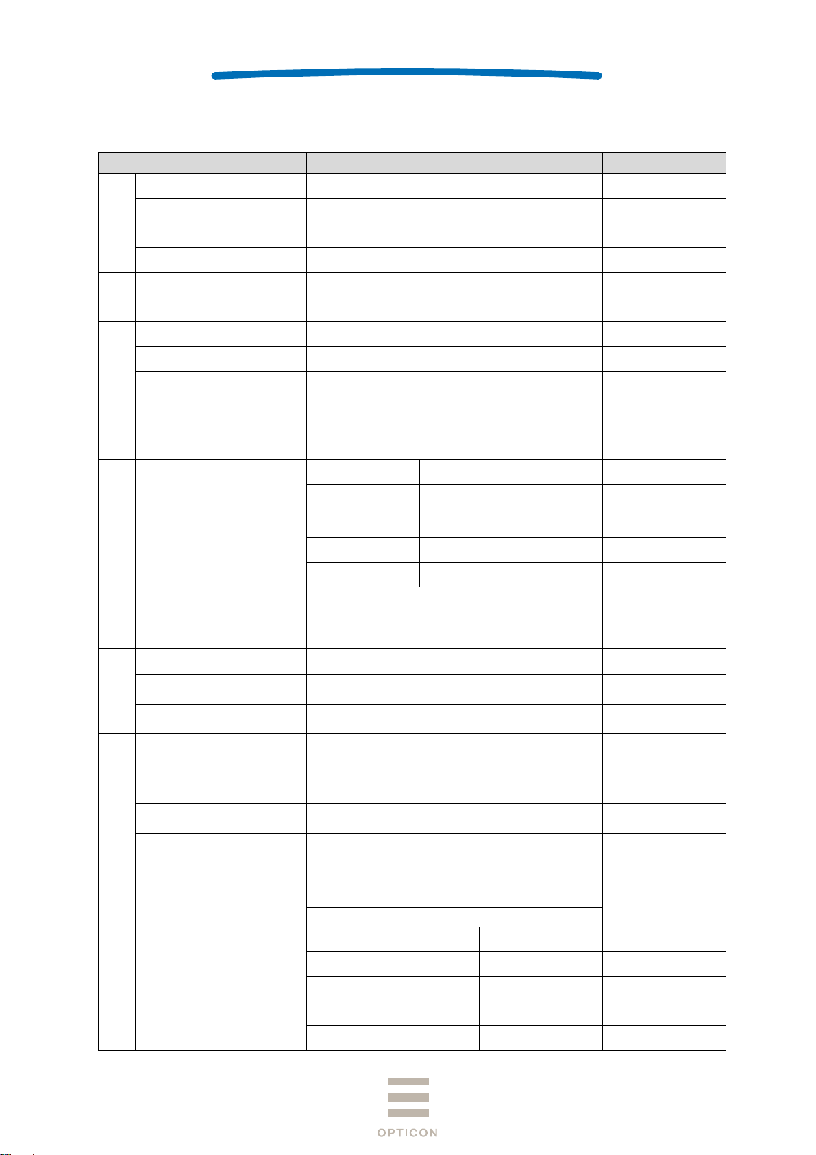
3 Basic Specifications
Item Specification Note
CPU 32 bit CISC / 96 MHz
Section
Control
FROM 512 Kbyte + 32 Kbyte
OPN-2102i
1st
SRAM 96 Kbyte
FROM (storage) 1 Mbyte
Section
Input
Key type 2 key: trigger, function
Indicator
LED 2 bi-colors LEDs (red, green) and 1 blueLED
Buzzer Loudness (3-level) / tone adjustable
Vibration motor Strength (3-level) / duration adjustable
RTC
Contents Year, month, date, hour, minute, second
Accuracy ± 90 seconds per month
Frequency 2402 ~ 2480 MHz
Specification Bluetooth Ver 2.1 compliant
Bluetooth
Interface
Communication
distance
10 m
Output level Class 2
Profile SPP / HID
NFC tag
USB
Light-emitted element Red laser diode
Section
Optical
Laser wavelength
/ output
ISO/IEC 14443 TYPE A, TYPE B
JISX6319-4
・Full-Speed 12Mbps ( HID/COM )
・Hi-Power Bus-powered supported
650±10nm 1mW or less
Scan rate 100±20scan/sec
JAN,EAN,UPC-A,UPC-E,NW-7 (Codabar),
Symbologies
Industrial 2 of 5,Interleaved 2 of 5,
Code 11,Code 39,Code 93,Code 128
Minimum resolution Code 39 : 0.076mm
Supported 1D Symbologies
Curvature
Barcode width
R ≥ 15 mm ( 8-digit JAN)
R ≥ 20 mm (13-digit JAN)
100 mm wide 0.2 mm resolution Code 39 (DOF 150
mm) is readable:
Pitch : α ≦±35°
Scan angle
Skew : β ≦±50° (Excluding dead zone)
Tilt : γ ≦±20°
Resolution (1.0) 50 ~ 420
For data area only
Data and time are lost
when the main battery
is removed.
Not guaranteed.
Max output 4 dBm
Wavelength in
temperature 25℃
Refer to Section 17.
for details
PCS 0.9
PCS 0.9
PCS 0.9
Depth of Field Code 39
Resolution (0.5) 45 ~ 340
Resolution (0.25) 40 ~ 250
Resolution (0.15) 40 ~ 155
Resolution (0.127) 45 ~ 130
7
Page 8
SPECIFICATIONS MANUAL
2
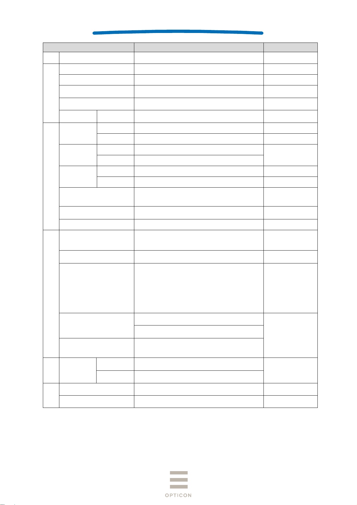
Item Specification Note
Minimum PCS 0.3 or more
OPN-2102i
1st
MRD 32% or more
Main battery Lithium-polymer 600 mAh (typ.)
Power Section
Up-time 25 hours or more
Feeding system
Electromagnetic guidance wireless charging,
microUSB
Operating (charging) voltage 4.5 ~ 5.5V
Current
consumption
Charging Less than 500 mA
Operating -10 ~ 50°C
Temperature
Environmental Specifications
Storage -20 ~ 60°C
Operating 20 ~ 85%
Humidity
Storage 20 ~ 85%
Ambient light
immunity
Fluorescent 4,000 lx or less
Sunlight 80,000 lx or less
10 Hz ~ 100 Hz, acceleration of 19.6 m/s
Vibration
minutes per cycle, repeat once in each X, Y and Zdirection
Drop
Drop the scanner 18 times (6 faces x 3) from a
height of 150 cm onto a concrete floor
Dust and drip proof IP54 equivalent
JIS C 6802:2011 Class2
LED safety
IEC 60825-1 Ed.2: 2007 Class 2
CDRH Class Ⅱ
Product safety
Regulatory Compliance
EN60950-1:2005
IEC60950-1:2006
EN 55024:2010
EN 55032:2012+AC: 2013
EN 301 489-1 V1.9.2
EMC
EN 301 489-17 V2.2.1
EN 300 328 V1.9.1
EN 302 291-2 V1.1.1
FCC Part 15 Subpart C, Subpart B ClassB
VCCI Class B
CE Marking
European conformity
Certification for Construction Design of Specified
Radio Equipment
Other
Immunity
Test
ESD
No
distraction
No
malfunction
Features
Physical
Dimensions 83.0 × 36 × 21.5 (WDH mm)
Bluetooth logo certification
MFi license
Air discharge (direct): ±15 kV
Air discharge (direct): ±8 kV
, 60
*1
Charging with USB
No condensing
No frost
For residential,
commercial and lightindustrial
environments
Conditions:
IEC61000-4-2
compliant
Weight Approx. 60 g
Excluding accessories
*1: When a barcode is read twice every 10 seconds at room temperature in a constant Bluetooth connection (SPP
master mode).
8
Page 9
4 Detailed View
SPECIFICATIONS MANUAL
OPN-2102i
1st
1
5
8
9
6
7
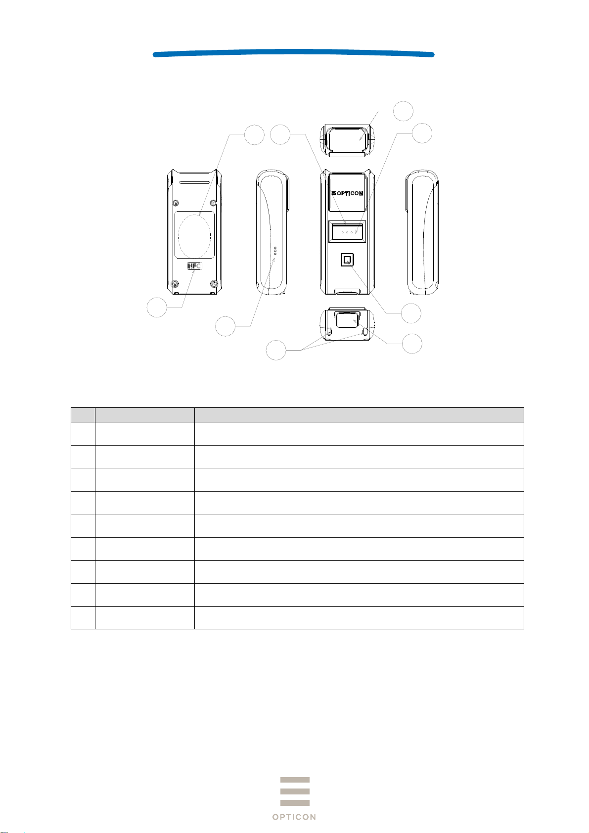
Figure 1: Detailed View
No Name Description
1 Scan Window
The laser light is emitted through this window. Ensure that the lens is
not exposed to dust and dirt before scanning.
3
4
2
2 USB Cap Cap for USB connector part used to make the scanner IP54 water tight.
3 Trigger Key Press this key to enable the laser and start reading barcodes.
4 Function Key The function of this key depends on the installed application.
5 LED
6 Buzzer Orifice Holes for buzzer.
7 Strap Orifice Holes for attaching a hand strap.
8 Charging Coil
9 NFC
Indicates operating status, such as bar code reading, Bluetooth
connection, warning etc.
The charging coil is located here with which the dedicated cradle can
supply power to the scanner.
This is the location of the NFC tag. Hold an NFC reader close to this
area when the tag has to be read.
9
Page 10
e
uBuCu
W
ePo
t
N
C
S
l
u
m
S
p
a
u
r
N
A
A(NC
a
a
a
p
C
t
w
p
SPECIFI
V
m
a
m
a
c
m
M
e
u
n
c
.
u
S
t
O
t
CATIONS
ANUAL
PN-2102i
1st
5 El
5.1 U
S
5.2
F
6 In
The OP
6.1 U
In
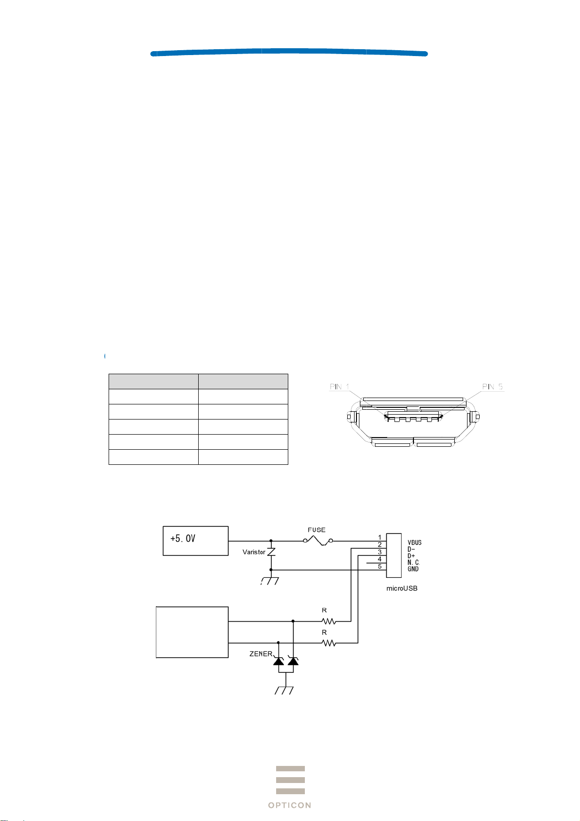
6.1.1
ctrical
SB
pply Voltag
s-power (C
rrent cons
ireless C
eding syste
wer consu
erface
-2102i sup
SB Interf
terface is F
onnecto
Signal
VC
DAT
DAT
GN
pecific
e
ass)
mption
harging
m
ption
pecific
orts two ty
ce
ll Speed US
ame
C
(-)
(+)
)
D
tions
: 4.5-5.5
: 500mA
: Less th
: Electro
: Less th
tions
es of interfa
B interface.
ontact Nu
1
2
3
4
5
ax (hi-pow
n 500mA
agnetic ind
n 5W
ces; USB a
ber
r)
ction
d Bluetooth
Fig
re 2: micro U
B B Connec
or
6.1.2
USB Interf
ce Circui
Po
Su
Microcontroller
er
ly
Figure 3:
Interface Cir
uit (USB)
USB Connec
tor
10
Page 11

SPECIFICATIONS MANUAL
t
t
6.2 Bluetooth
The specifications of the OPN-2102i Bluetooth interface are as follows:
Frequency : 2402 ~ 2480 MHz
Specification : Bluetooth Ver 2.1 compliant
Communication distance : 10 m
Output level : Class 2 (max 4 dBm)
Implemented profile : SPP / HID
Communication configuration : 1 to 1
Operating mode in communication : Master / Slave mode
Security mode : Authentication supported
Encryption : Encryption supported
6.3 NFC Tag
OPN2102i has NFC tag built-in which record Bluetooth device address.
Frequency: 13.56MHz
Standard : ISO/IEC 14443 TYPE A, TYPE B and JISX6319-4
Recorded Contents:
Rewriting from external: possible
Total 928 byte
NDEF
Record #1
ype: ”application/vnd.bluetooth.ep.oob”
OOB data length: 8 Byte
MAC address: 00:12:6A:xx:xx:xx
Record #2
ype: ”T”
TEXT data length: 15 Byte
TEXT data: ”00126Axxxxxx”
Free area
Reserved area
*xx will differ according to product.
OPN-2102i
1st
7 Optical Specifications
7.1 Basic Specifications
Item
Light-Emitting Element Red laser diode -
Emission Wavelength 650 ±10 (25° C) nm
Light Output < 1.0 μW
Scanning Method Bi-directional scanning -
Scanning Speed 100 ±20 scans/sec
Scan Angle 54 ±5 deg
Scan Angle
Effective Scan
Angle
44 (Min) deg
Characteristics
Unit
11
Page 12
SPECIFICATIONS MANUAL
7.2 Laser Scanning Standards
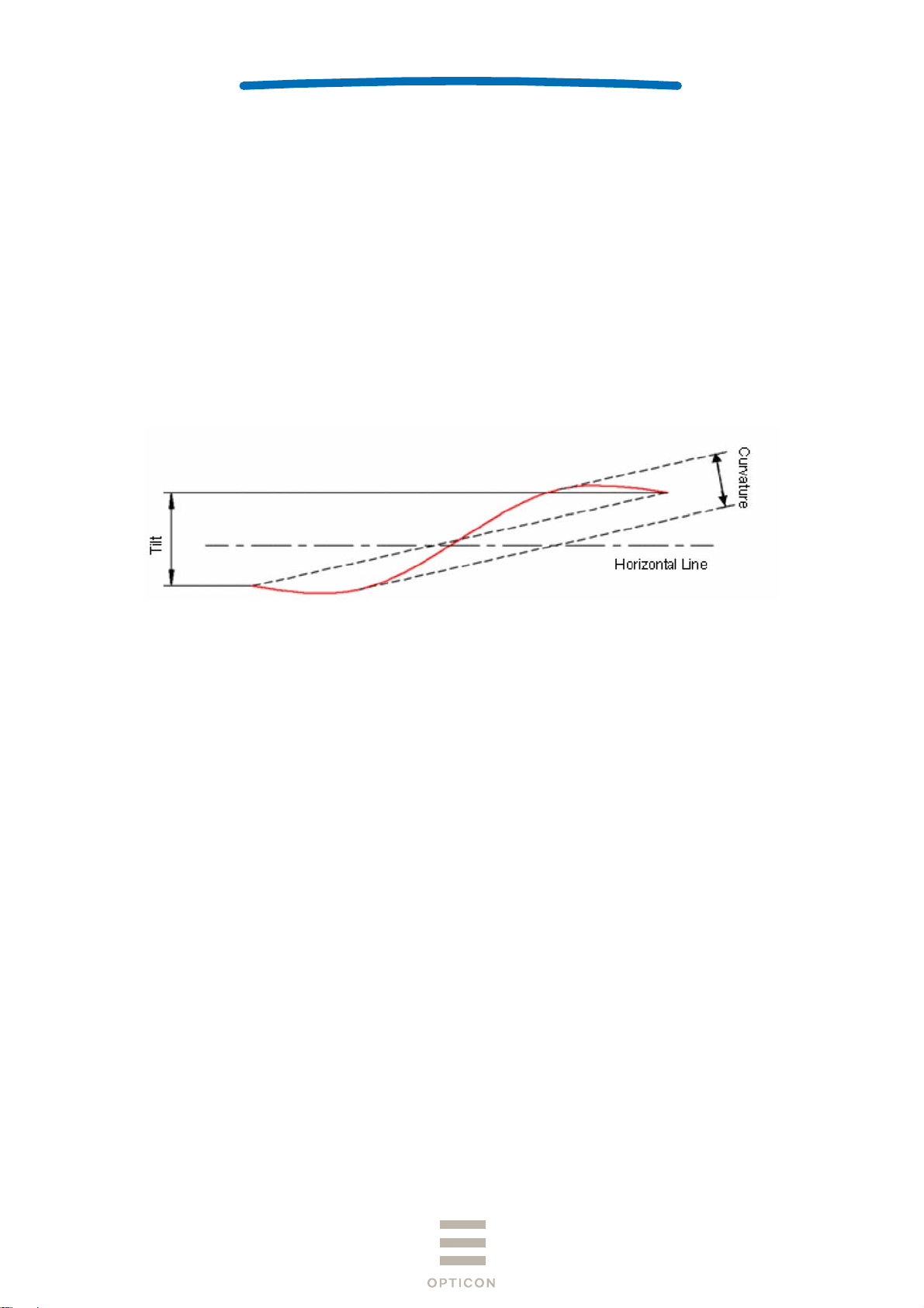
7.2.1 Laser Scanning Tilt
Vertical differences between both ends of a laser scanning line:
- Up to 1.2 degrees in a vertical direction from the scan origin (scanning mirror).
- Up to 3.1 mm measured at 150 mm from the scan origin and with zero skew angle.
- Measure in the middle of the scanning line.
7.2.2 Laser Scanning Curvature
The maximum differences between the laser scanning line and a straight line connecting the
both ends of the scanning line:
- Up to 1.27 degrees from the scan origin (scanning mirror).
- Up to 3.3 mm measured at 150 mm from the scan origin.
- Measure in the middle of the scanning line.
OPN-2102i
1st
Figure 4: Laser Scanning Specification
12
Page 13
SPECIFICATIONS MANUAL
8 Technical Specifications
Ambient conditions are as follows unless otherwise specified in each section:
<Conditions>
Ambient Temperature and Humidity Room temperature, room humidity
Ambient Light 500 ~ 900 lx
Barcodes Refer to Section 8.1.
Background Black
Power supply voltage
Reading Test Accept the performance with 10 consecutive successes
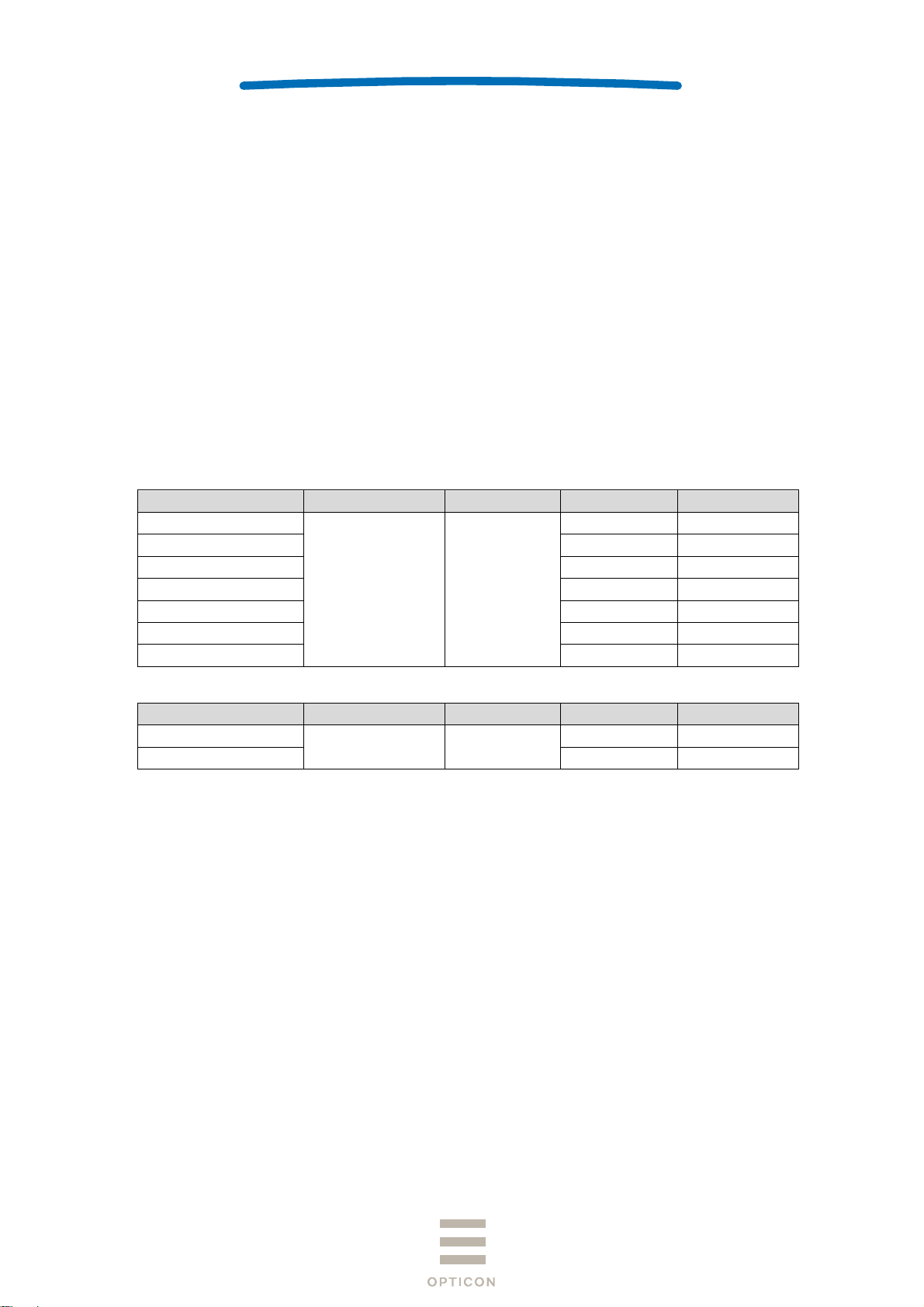
8.1 Barcode Test Sample
<Code 39>
Resolution Symbology PCS
1.0 mm
0.5 mm 18 mm 3
0.25 mm 10 mm 8
0.25 mm 10 mm 9
0.15 mm 7 mm 10
0.127 mm 5 mm 4
0.076mm 5 mm 5
<JAN>
Resolution Symbology PCS
0.26 mm
0.26 mm 10 mm 8
Code 39 0.9
5V (USB)
in reading. Each reading should be done in 0.5 seconds
or less.
Quiet Zone
25 mm 1
Quiet Zone
JAN 0.9
10 mm 13
No. of Digits
No. of Digits
OPN-2102i
1st
13
Page 14

SPECIFICATIONS MANUAL
8.2 Scan Area and Depth of Field
The scanner is able to read in the area between the two arcs that are centered on the scan
origin with a center line distance from the front of the scanner as indicated for each resolution.
Resolution No. of Digits Depth of Field (mm)
1.0mm 1 50 ~ 420
0.5mm 3 45 ~ 340
0.25mm 8 40 ~ 250
0.15mm 10 40 ~ 155
0.127mm 4 45 ~ 130
<Conditions>
Barcode : Code 39 specified in Section 8.1.
Angle : α = 0°, β = + 15°, γ = 0°
[ inch ]
[ mm ]
2" 4"
0
50 100 150 200 250 300
6" 8"
10" 12"
14" 16"0"
350
400
18"
450 500
OPN-2102i
20"
22" 24"
550
1st
600
Code 39
0.127mm ( 5mil )
0.15mm ( 6mil )
0.25mm ( 10mil )
0.5mm ( 20mil )
1.0mm ( 40mil )
8" 9" 10"
200 225 250
7"
175
3"
75
50
25
0
0" 2"2" 1"1"
25
50
75
3"
4" 4" 5" 6"5"6"
100 100 125 150125150
175
7"
200225250
8"9"10"
[ mm ]
[ inch ]
Figure 5: Scan Area and Depth of Field
14
Page 15

SPECIFICATIONS MANUAL
8.3 Printed Contrast Signal (PCS)
PSC 0.3 or higher (70% or higher reflectivity of space and quiet zone)
PCS =
Note:
Be sure to keep the optical window clean without dirt or scratches, or it may have a detrimental effect on
the reading characteristics.
Reflectance of white space – Reflectance of black bar
Reflectance of white space
8.4 Minimum Resolution
Minimum Resolution 0.076mm
<Conditions>
Barcode Code 39 specified in Section 8.1
Distance 60 mm from the front edge of the scanner
Angle Skew angle β = 15°
OPN-2102i
1st
8.5 Pitch, Skew and Tilt
Pitch : α ≦ ±30°
Skew : β ≦ ±50°
Dead Zone : β ≦ ±8 °
Tilt : γ ≦ ±20°
<Conditions>
Bar code <Pitch, Skew and Dead Zone>
Resolution 0.25 mm, 9-digit Code 39 specified in Section 8.1.
<Tilt>
Resolution 0.26 mm, JAN-13 specified in Section 8.1.
Distance 100 mm from the edge of the scan engine
Curvature R = ∞
Angle Pitch angle : β = +15°, γ = 0°
Tilt angle : α = 0°, β = +15°
Skew angle / Dead zone: α = 0°, γ = 0°
(Excluding dead zone)
(Decoding may fail in some areas as a result of specular reflection)
-
β
-
+
-
γ
+
+
Figure 6: Pitch, Skew and Tilt
15
Page 16
8.6 Curvature
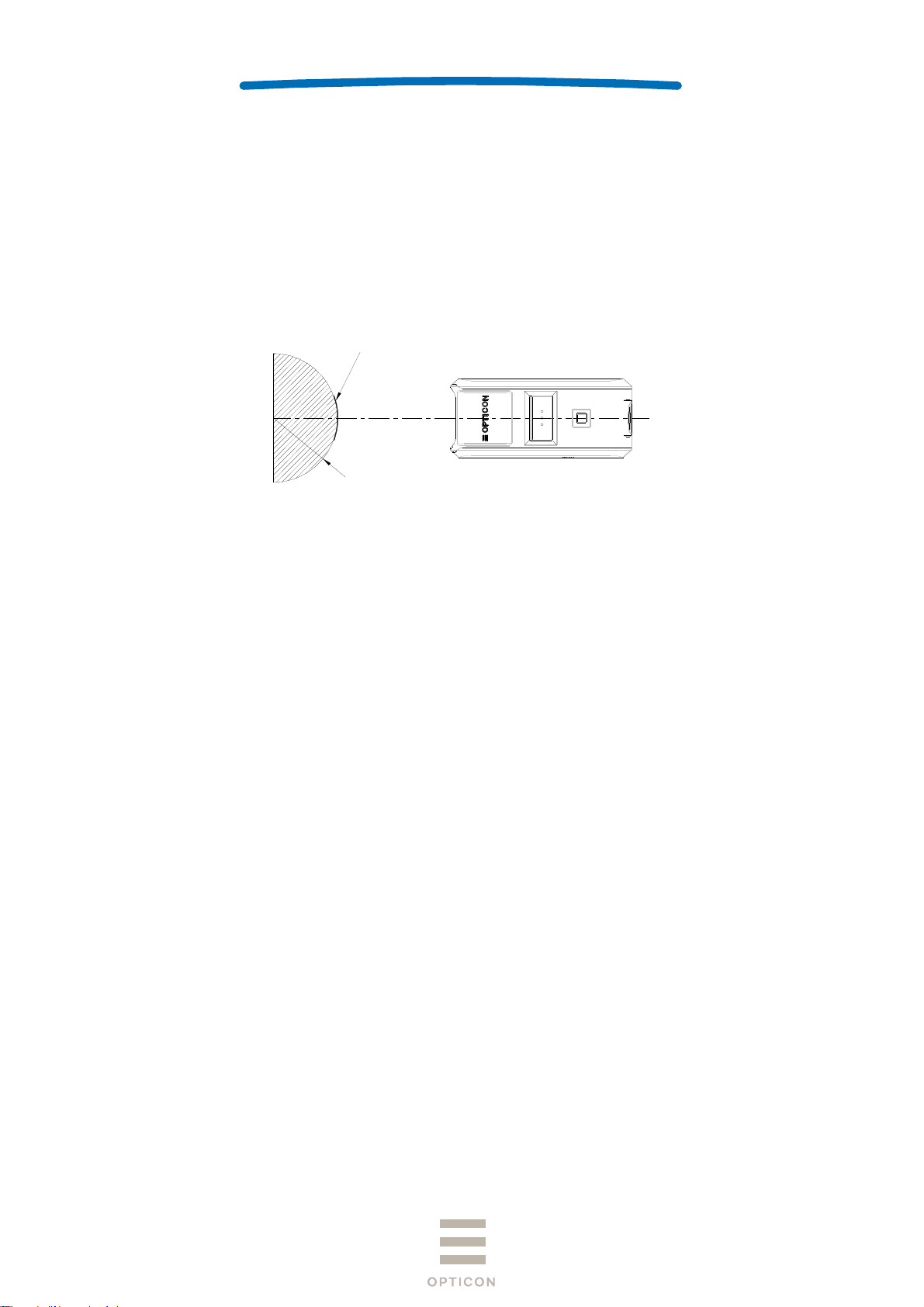
8-digit JAN: R ≧ 15 mm
13-digit JAN: R ≧ 20 mm
<Conditions>
Barcode Resolution 0.26 mm, JAN specified in Section 8.1.
Distance 100 mm from the edge of the scan engine
Angle Skew angle β = +15°
SPECIFICATIONS MANUAL
バーコード
Bar code
R
OPN-2102i
1st
Figure 7: Curvature
Note:
The reading performance may deteriorate if there is specular reflection of the laser light, this typically will occur
when the reflectivity of the barcode is high.
9 Environmental Specifications
9.1 Temperature
Scanning performance is guaranteed when the ambient temp. is within the following range:
Operating Temperature: -10 ~ 50
Storage Temperature : -20 ~ 60
Please charge when the temperature is between 0 and 40°C. When the temperature is over 40°C,
charging may stop to prevent battery breakdown..
9.2 Humidity
Scanning performance is guaranteed when the ambient humidity within following range:
Operating Humidity: 20 ~ 85%RH (no condensation, no frost)
Storage Humidity: 20 ~ 85%RH (no condensation, no frost)
°C
°C
16
Page 17

SPECIFICATIONS MANUAL
9.3 Ambient Light Immunity
Scanning performance is guaranteed when the illumination on a barcode surface is between
zero and the following values:
Incandescent light: 4,000 lx
Fluorescent light: 4,000 lx (excluding high-frequency lighting)
Sunlight: 80,000 lx
<Conditions>
Barcode: Optoelectronics Test Sample
Resolution 0.25 mm, 9-digit Code 39,
Quiet Zone 10 mm, N/W Ratio = 1 : 2.5
Distance: 100 mm from the front edge of the scanner
Angle:
Curvature: R = ∞
Power-supply voltage: 5.0V
* Avoid direct or specula reflection from the laser beam as it may blind the scanners optical receiver.
α = 0°, β =+15°, γ = 0°
9.4 Dust and Drip Proof
IEC IP54 equivalent
Protection against solid objects: Level 5 equivalent (Dust proof type)
Prevent dust ingress to inside. Even if slight dust intrusion will not inhibit normal operation.
Protection against liquids: Level 4 equivalent (Splash proof type)
Protected against water splash from any direction.
* () is JIS drip-proof type.
OPN-2102i
1st
9.5 Vibration Strength (without packing)
There shall be no sign of malfunction after the following vibration test.
Vibration test: Increase the frequency of the vibration from 10Hz to 100Hz at an accelerated
velocity of 19.6m/s2 (2.0 G) for 30 minutes (60 minutes per cycle) in non-operating state.
Repeat this in each X, Y and Z direction.
9.6 Vibration Strength (in individual packing)
There shall be no sign of malfunction after the following vibration test.
Vibration test: Increase the frequency of the vibration from 10Hz to 100Hz at an accelerated
velocity of 19.6 m/s2 (2.0 G) for 30 minutes (60 minutes per cycle) in individually packaged state.
Repeat this in each X, Y and Z direction.
17
Page 18
SPECIFICATIONS MANUAL
9.7 Drop Impact Strength (without packaging)
There shall be no sign of malfunction after the following drop test.
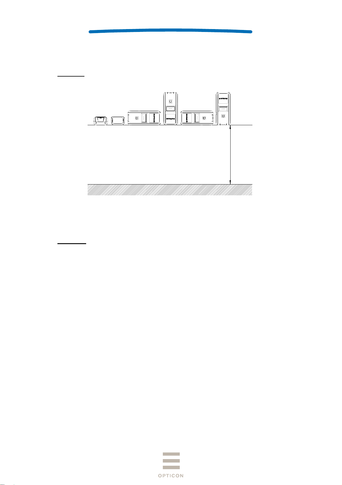
Drop test: Drop the scanner 18 times in total (3 times at each 6 face), from a height of 150 cm
onto a concrete floor as shown below.
150cm
OPN-2102i
1st
Figure 8: Drop Test
9.8 Drop Impact Strength (in individual packaging)
There shall be no sign of malfunction after the following drop test.
Drop test: Drop an individually packaged scanner 10 times in total, at any of 1 corner, 3 edges,
and 6 faces, from a height of 150 cm onto a concrete floor.
9.9 Electrostatic Discharge Immunity
Air discharge ±8 kV max. (No malfunction)
±15 kV max. (No destruction)
Measurement environment An electrostatic testing device compliant with IEC 61000-4-2
Discharge resistance 330 Ω
Charging capacitor 150 pF
18
Page 19

SPECIFICATIONS MANUAL
10 Regulatory Compliance
10.1 LED Safety
JIS C 6802:2011 Class 2
IEC 60825-1 Ed.2: 2007 Class 2
CDRH Class Ⅱ
10.2 Product Safety
EN60950-1:2005
IEC60950-1:2006
10.3 EMC
R & TTE Directive
・EN 55024:2010
・EN 55032:2012+AC: 2013
・EN 301 489-1 V1.9.2
・EN 301 489-17 V2.2.1
・EN 300 328 V1.9.1
・EN 302 291-2 V1.1.1
FCC Part 15 Subpart C, Subpart B ClassB
Federal Communications Commission Notices
This device complies with FCC radiation exposure limits set forth for an
uncontrolled environment.
This product complies with Part 15 of the FCC Rules. Operation is subject to the
following two conditions:
(1) this device may not cause harmful interference, and
(2) this device must accept any interference received, including interference that
may cause undesired operation.
Harmful Interference Notice
This product has been tested and complies with the specifications for a Class B
digital device, pursuant to Part 15 of the FCC Rules. These limits are designed to
provide reasonable protection against harmful interference in a residential
installation. This equipment generates, uses, and can radiate radio frequency
energy and, if not installed and used according to the instructions, may cause
harmful interference to radio communications. However, there is no guarantee
that interference will not occur in a particular installation. If this equipment does
cause harmful interference to radio or television reception, which is found by
turning the equipment off and on, the user is encouraged to try to correct the
interference by one or more of the following measures:
• Reorient or relocate the receiving antenna
• Increase the separation between the equipment or devices
• Connect the equipment to an outlet other than the receiver's
• Consult a dealer or an experienced radio/TV technician for assistance
Changes or modifications not expressly approved by the party responsible for
compliance could void the user’s authority to operate the equipment.
OPN-2102i
1st
19
Page 20
C
O
o
oRoele
e
M
e
a
r
p
e
o
o
n
a
u
a
e
o
a
s
B
n
m
n
m
t
y
B
t
C
o
e
P
b
h
c
i
1
L
s
e
s
z
b
s
SPECIFI
a
a
o
p
e
n
a
AcO
2
t
0
h
m
e
o
d
M
r
n
p
r
t
h
r
d
a
o
n
e
o
u
o
e
o
m
d
o
a
o
c
h
O
f
CATIONS
ANUAL
PN-2102i
1st
V
CI Class B
Th
is is a Class
quirement of
R
Eq
uipment (VC
y cause radi
m
product, to
he Voluntary
I). If this is u
interference.
e used in a d
Control Coun
ed near a ra
mestic envir
cil for Interfer
io or televisi
nment, base
nce from Inf
n receiver in
on the Tech
rmation Tec
domestic en
nical
nology
vironment, it
10.4
11 R
ther
・
Bluetooth l
・
MFi license
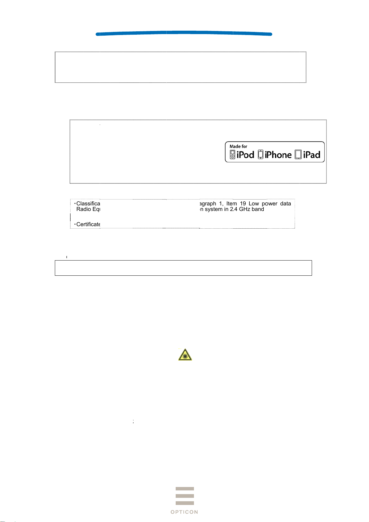
“Made fo
mean that
connect s
and has b
performan
operation
regulatory
accessory
performan
・
Certificatio
・Classific
Radio Eq
・Model N
・Certificat
HS
R
HS compli
HS: The re
ctronic equi
go certificati
iPod,” “Mad
an electronic
ecifically to i
en certified
ce standards.
f this device
standards. Pl
with iPod, iP
ce.
for Constru
tion of Specif
ipment
me
Number
nce.
triction of th
pment, 201
on
for iPhone,”
accessory h
od, iPhone,
y the develo
Apple is not r
or its complia
ease note th
one, or iPad
tion Design
ed
e use of cer
/65/EU
nd “Made fo
s been desig
r iPad, respe
er to meet A
sponsible fo
nce with safe
t the use of t
may affect wi
of Specifie
rticle 2 Par
ommunicati
PA-26X1
01-125603
ain hazardo
iPad”
ed to
ctively,
ple
the
y and
is
eless
Radio Equi
graph 1, Ite
n system in 2
us substanc
pment
19 Low p
.4 GHz band
s in electri
wer data
al and
12 R
MTBF (
13 Pr
13.1 P
・
・
・
・
liability
ean Time
ecautio
recaution
Do not star
It may har
Do not poi
It may har
Do not star
It may har
Use of con
herein ma
etween Fail
s
against
e into the la
your eyes.
t the laser d
their eyes.
e into the b
m your eyes
rols or adju
result in ha
ures) 50,
aser Lig
er light fro
irectly at oth
am with opti
.
tments or p
ardous radi
00 hours
t
the scanni
ers’ eyes.
cal instrum
rformance
ation expos
g window.
nts.
f procedure
re.
s other than
those speci
ied
20
Page 21

SPECIFICATIONS MANUAL
13.2 Handling
Handle this product carefully. Do not deliberately subject it to any of the following.
(1) Shock:
・ Do not drop this product from a height greater than specified in this manual.
・ Do not place this product under or between any heavy items.
・ Do not swing the cable around.
(2) Temperature Conditions:
・ Do not use this product at temperatures outside the specified range.
・ Do not pour boiling water on this product.
・ Do not throw this product into a fire.
(3) Foreign Materials:
・ Do not immerse this product in water or other liquid.
・ Do not expose this product to chemicals.
Others
・ Do not disassemble this product.
・ Do not use this product near a radio or a TV. It may cause reception problems.
・ This product may be affected by a momentary voltage drop caused by lightning.
・ Please use within the range of operating voltage. Using outside of operating voltage may
cause malfunction.
・ Do not attach piece of metal or metal foil to the back of charging coil stored part and NFC coil
stored part. Also, do not fix anything that prevents placing to charging cradle.
・ Please securely close the USB cap to keep the waterproof.
・ Do not pull strong, fold and bend the cables.
・ Do not add shock or apply load to jack and connector.
・ When charging is completed, please remove USB cable from connector.
OPN-2102i
1st
13.3 Radio Law
This product qualifies as specified radio equipment for radio stations of 2.4 GHz band data
communication system and has obtained the Certification for Construction
Design of Specified Radio Equipment. Therefore, radio station license is not required in Japan.
The following activities are prohibited under the Radio Law:
・Remodelling and disassembly
・Peeling off the certificate label
Do not use this equipment under the following environment, as radio interference may affect
other device and end up with causing physical or material damage.
・Safety apparatus and medical device for human body protection
・Environment where is concerned to cause serious damage
21
Page 22

SPECIFICATIONS MANUAL
13.4 Bluetooth
・This product supports Bluetooth wireless communication with other Bluetooth devices that
have the same profile
・This product complies with Bluetooth standards; however, its communication performance
with untested devices is not guaranteed.
・Bluetooth devices use the 2.4 GHz frequency band that is shared among other devices. It
may affect the communication speed and distance between this product and the host device.
・The communication speed and distance vary depending on the interference and radio wave
condition between this product and the host device.
13.5 Frequency Band
This product uses the 2.4 GHz frequency band. Read carefully the followings before using this
product.
In the frequency band of this product, scientific, medical and industrial devices including
microwaves are used. Also other radio stations including local private radio station for mobile
object identification requiring license for such as manufacturing lines at factories, specific
power-saving radio station requiring no license and amateur radio station are managed.
1. Make sure that “other radio stations” are not managed in the frequency band 2.4 GHz before
using this product.
2. In case that radio interference occurs between this product and “other radio stations,” change
the service space immediately, or stop transmitting radio wave to avoid the interference.
3. If you have any questions or troubles, please contact our sales office.
OPN-2102i
1st
* This specification manual is subject to change without prior notice.
22
Page 23

SPECIFICATIONS MANUAL
14 Product Labels
The product labels are affixed to the scanner as shown below.
OPN-2102i
1st
Figure 9: Product Label Position
23
Page 24
a
n
As
W
g
P
a
o
t
o
w
i
e
h
k
c
g
0
h
a
o
e
d
SPECIFI
5
0
o
p
w
M
P
s
c
G
1
O*UF2
O
e
o
2
*
*
u
『
c
y
O
-
e
CATIONS
ANUAL
PN-2102i
1st
15 P
15.1 I
ckagin
dividual
sembled p
eight: Appr
Place in
*Place
Specifi
ackagin
ckage size:
x. 140g
OPN-2
o the box wit
d
wn without t
ith Opticon l
ations
Approx. 12
12i
folded side
ped.
go upward.
× 112 × 40
(WDH mm)
Place the M
with conn
Place wit
bac
croUSB cabl
ctor far side.
taped side
ward.
*Do not fol
Place pr
neck stra
side, th
the barcode
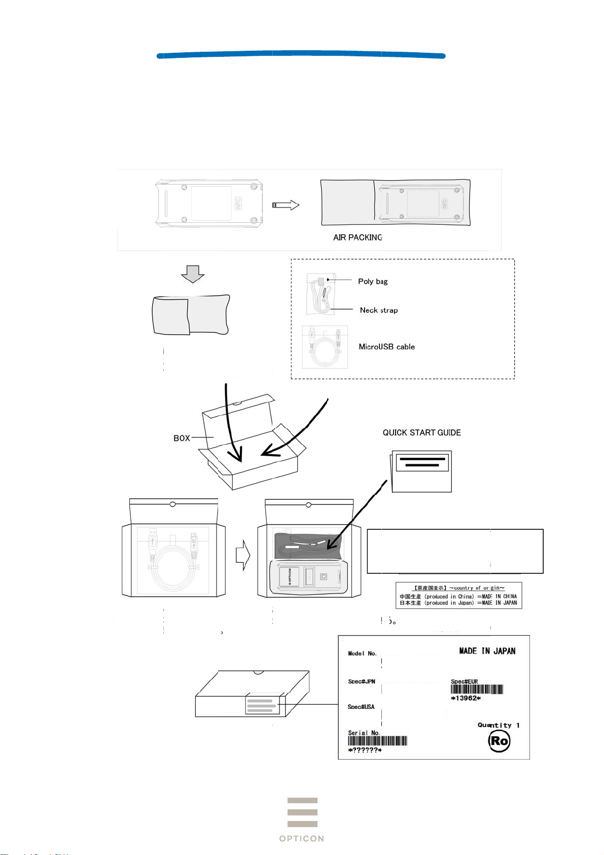
Figure 1
duct in front
to the USB
an place QS
hen pasting
: Individual
ide, and plac
able connect
on the top.
OPN-2
*UF2
ackaging
Display
1
3456=Produ
Displa
r
02i-WHT
PN2102
PN2102
Individ
for the Serial
『123456』
t serial numb
6-digets seri
al box label:
No.
r.
al number.
3A0002
24
Page 25

C
0AsW
b
P
o
a
o
y
n
g
*OPN2102
I-*13962*
4
o
l
SPECIFI
5
1
09*
4
r
M
2
P
m
eTh
O
CATIONS
ANUAL
PN-2102i
1st
15.2
ollective
1
0pcs per b
sembled p
eight: Appr
Enter battery t
attery」and pho
22-31-31」. And
either side of the
ackagin
x
ckage size
x. 15kg
Packing box: 5B
pe 「Lithium ion
e number 「01-2
place 1pc next t
packing box labe
: Approx.
0008 (100pcs pe
-
.
95 × 520 ×
box)
45 (WDH
m)
e order of serial-
5 St
eps
No.
Figure 1
1: Collective
ackaging
25
Page 26
16 Physical Features
16.1 Dimensions
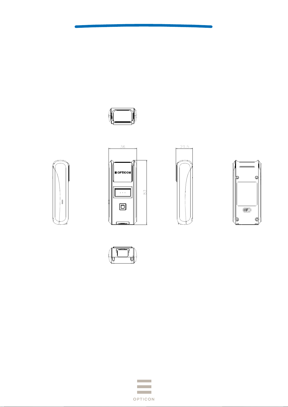
83.0 × 36.0 × 21.5 (DWH mm)
16.2 Weight
Approx. 60 g (excluding accessories)
16.3 Mechanical Drawing
SPECIFICATIONS MANUAL
OPN-2102i
1st
Unit: mm
Figure 12: Mechanical Drawing
26
Page 27
SPECIFICATIONS MANUAL
17 Supported Symbologies
17.1 Default Setting
The scanner is set to default by reading the following menu label.
Recorded contents of the NFC tag will also return to default.
Function Menu label Menu code
OPN-2102i
1st
SET
Default
END
_ZZ_
_SO_
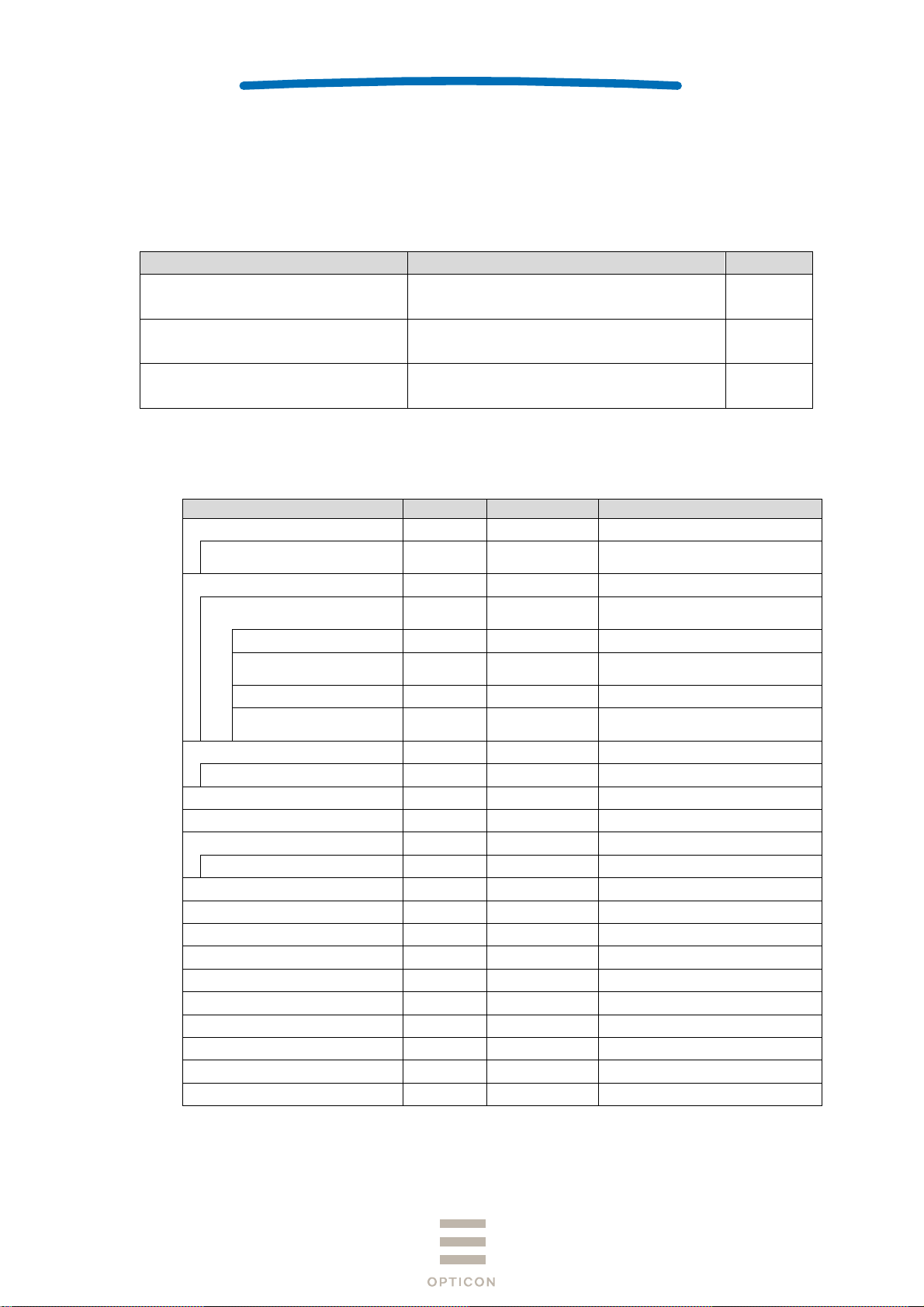
_ZZ_
17.2 Supported Symbologies
17.2.1 1D Barcodes
Code type Default Minimum length Note
UPC ○ -
UPC Add-on 2
UPC Add-on 5
EAN (JAN) ○ -
EAN Add-on 2
EAN Add-on 5
EAN-13 ○
EAN-8 ○
Code 39 ○ 1 Not transmit ST/SP
Tri-Optic ○ - Not transmit ST/SP
Codabar (NW7) ○ 5 Not transmit ST/SP
Industrial 2 of 5 ○ 5
Interleaved 2of 5 ○ 6
S-Code 5
Code 128 ○ 1 GS1 conversion (setting required)
Code 93 ○ 1
IATA ○ 5
MSI/Plessey ○ 3
UK/Plessey 2
TELEPEN ○ 1
Code 11 1
Matrix 2 of 5 5
Chinese Post Matrix 2 of 5 -
Korean Postal Authority -
EAN-13 Add-on 2
EAN-13 Add-on 5
EAN-8 Add-on 2
EAN-8 Add-on 5
ZZ
SO
ZZ
27
Page 28

SPECIFICATIONS MANUAL
17.2.2 GS1 Databar, Composite Code
Code type Default Note
GS1 DataBar
・GS1 DataBar Omnidirectional
・GS1 DataBar Truncated
・GS1 DataBar Stacked
・GS1 DataBar Stacked Omnidirectional
GS1 DataBar Limited
GS1 DataBar Expanded
・GS1 DataBar Expanded
・GS1 DataBar Expanded Stacked
OPN-2102i
1st
GS1
conversion (setting required)
28
 Loading...