

Page 1

Set up your personal configuration
Universal menu book
bar code configuration
and commands manual
Page 2

OPTICON UNIVERSAL MENU BOOK
Set up your personal configuration
Universal menu book
bar code configuration
and commands manual
ver. 10 © January 2006
Ui
Page 3

Regulatory Approvals
FCC Statement
This equipment has been tested and found to comply with the limits for a Class B digital
device, pursuant to Part 15 of the FCC Rules. These limits are designed to provide reasonable
protection against harmful interference in a residential installation.
This equipment generates, uses and can radiate radio frequency energy and, if not installed and
used in accordance with the instructions, may cause harmful interference to radio communications. However, there is no guarantee that interference will not occur in a particular installation.
If this equipment does cause harmful interference to radio or television reception, which can be
determined by turning the equipment off and on, the user is encouraged to try to correct the
interference by one of the following measures:
Reorient or relocate the receiving antenna.
Increase the separation between the equipment and receiver.
Connect the equipment into an outlet on a circuit different from that to which the receiver
is connected.
Consult the dealer or an experienced radio/TV technician for help.
To assure continued compliance, any changes or modifications not expressly approved by the
party responsible for compliance could void the user's authority to operate this equipment.
(Example - use only shielded interface cables when connecting to computer or peripheral
devices).
FCC Radiation Exposure Statement
This equipment complies with FCC RF radiation exposure limits set forth for an uncontrolled
environment. This equipment should be installed and operated with a minimum distance of 20
centimeters between the radiator and your body.
This device complies with Part 15 of the FCC Rules. Operation is subject to the following two
conditions:
(1) This device may not cause harmful interference, and
(2) This device must accept any interference received, including interference that may cause
undesired operation.
This transmitter must not be co-located or operating in conjunction with any other antenna or
transmitter.
The antennas used for this transmitter must be installed to provide a separation distance of at
least 2.5 cm from all persons and must not be co-located or operating in conjunction with any
other antenna or transmitter.
Channel
The Wireless Channel sets the radio frequency used for communication.
•Access Points use a fixed Channel. You can select the Channel used. This allows you to
choose a Channel which provides the least interference and best performance. In the USA
and Canada, 11 channel are available. If using multiple Access Points, it is better if adjacent
Access Points use different Channels to reduce interference.
• In "Infrastructure" mode, Wireless Stations normally scan all Channels, looking for an
Access Point. If more than one Access Point can be used, the one with the strongest
signal is used. (This can only happen within an ESS.)
• If using "Ad-hoc" mode (no Access Point), all Wireless stations should be set to use the
same Channel. However, most Wireless stations will still scan all Channels to see if there
is an existing "Ad-hoc" group they can join.
Note:
This equipment marketed in USA is restricted by firmware to only operate on 2.4G channel 1-11
Page 4

OPTICON UNIVERSAL MENU BOOK
CAUTION: This information is subject to
change without prior notice.
Copyright 2006, Opticon Sensors Europe
B.V. All rights reserved.
LIMITED WARRANTY AND DISCLAIMERS
Under all circumstances this manual should be
read attentively, before installing and or using
the product.
This manual may not, in whole or in part, be
copied, photocopied, reproduced, translated or
converted to any electronic or machine
readable form without prior written consent of
Opticon Sensors Europe.
Serial number
A serial number appears on all Opticon
products. This official registration number is
strictly related to the device purchased. Make
sure that the serial number appearing on your
Opticon device has not been removed.
Removing the serial number might affect the
warranty conditions and liability
disadvantageously, so please be strict at
maintaining the label with serial number on the
Opticon product.
Warranty / Warranty period / Liability
Unless otherwise agreed in a contract, all
Opticon products are warranted for the period
of two years after purchase, covering defects in
material and workmanship. Opticon will repair
or, at its opinion, replace products that prove to
be defective in material or workmanship under
proper use during the warranty period. Opticon
will not be liable in cases where modifications
are made by the customer. In such case the
standard repair charge will be applicable. The
standard charge for repair will also be
applicable in cases where no defect is found at
all. These rules also apply for products that are
still under warranty . Under no circumstance will
Opticon Sensors Europe, be liable for any
direct, indirect, consequential or incidental
damages arising out of use or inability to use
both the hardware and software, even if
Opticon has been informed about the possibility
of such damages.
Packaging
The packing materials are not harmful for the
environment. We recommend that you save all
packing material, as it should be used
whenever you need to transport your scanner
(eg. for service). Damage caused by improper
repacking is not covered by the warranty.
Trademark
Trademarks used are property of their
respective owners.
Uii
Page 5

OPTICON UNIVERSAL MENU BOOK
TABLE OF CONTENTS
0. Introduction .............................................U1
1. Defaults ....................................................U5
2. Interface ...................................................U7
2.1. RS232 options.....................................U8
2.1.1. Baud rate settings................................U9
2.1.2. Data, parity, stop bits .........................U10
2.1.3. Handshaking......................................U11
2.1.4. Intercharacter delay for RS232.......... U14
2.2. Keyboard wedge/USB options........... U15
2.2.1. Keyboard layout................................. U16
2.2.2. Special options.................................. U18
2.2.3. Intercharacter delay for
wedges/USB...................................... U19
2.3. Wireless options................................ U21
2.3.1. Bluetooth address..............................U22
2.3.2. Bluetooth security.............................. U24
2.3.3. Trigger connection options................. U25
2.3.4. Trigger disconnect options................. U26
2.3.5. Auto disconnect options............ ... ...... U27
2.3.6. Auto reconnect options...................... U28
2.3.7. Wireless power saving ....................... U29
2.3.8. Memorizing........................................ U30
3. Code options .........................................U33
3.1. Setting of readable codes.................. U34
3.1.1. Enabling a single read. Code............. U34
3.1.2. Enabling of readable codes ............... U38
3.2. Setting of number of characters......... U42
3.3. Setting code specific options............. U46
3.3.1. Options for UPC-A............................. U47
3.3.2. Options for UPC-E............................. U48
3.3.3. Options for EAN-13 and EAN-8......... U50
3.3.4. Options for Code 39 and It.Pharm..... U52
3.3.5. Options for Codabar.......................... U55
3.3.6. Options for 2of5 and S-Code............. U59
3.3.7. Options for IATA ........................... .... ..U61
3.3.8. Options for MSI/Plessey.................... U62
3.3.9. Options for Telepen............................ U64
3.3.10.Options for UK/Plessey.................... ..U65
3.3.11.Options for Code 128 and EAN-128..U66
3.3.12.Options for Code 93...........................U68
3.3.13.Options for Code 11...........................U70
3.3.14.Options for Korean Postal Authority... U71
3.3.15.Options for RSS................................. U72
3.3.16.Options for Composite Codes............ U73
3.3.17.Options for DataMatrix........................U75
3.3.18.Options for Aztec................................U76
3.3.19. Options for QR Code..........................U77
3.3.20.Options for Maxicode..........................U78
3.3.21.Options for PDF417............................U79
3.3.22.Options for MicroPDF417...................U80
4. String options........................................U81
4.1. Case conversion.................................U82
4.2. Set prefix and suffix............................U83
4.2.1 Set prefix ............................... .............U88
4.2.2. Set suffix.............................................U91
4.3.1. Direct input keyboard keys .................U94
4.3.2. Direct input character misc.................U97
4.3.3. Direct input numeric..........................U100
4.3.4. Direct input character.......................U101
4.3.5. Direct input lower case character .....U103
4.3.6. Direct input control character............U105
4.3.7. Direct input code id/length................U108
5. Read options .......................................U109
5.1. Read mode options ..........................U110
5.1.1. Multiple read reset time....................U112
5.1.2. Quiet zone options............................U113
5.1.3. Auto trigger options..........................U114
5.2. Read time options.............................U115
5.3. Power co ntrol....................................U117
5.4. Redundancy .....................................U119
5.5. Positive and negative bar codes.......U120
5.6. Resolution and density.....................U121
6. Indicator options.................................U123
6.1. Buzzer settings.................................U124
6.2. Good read LED.................................U126
7. Miscellaneous ..................................... U127
7.1. Diagnostics.......................................U128
7.2. Serial configuration support..............U129
Appendix..............................................U131
A. Trouble shooting ...............................U131
B. Glossary of terms .............................U132
C. Example codes.................................U136
Table of contents
Uiii
Page 6

OPTICON UNIVERSAL MENU BOOK
Uiv
Page 7
OPTICON UNIVERSAL MENU BOOK
INTRODUCTION
This menu book is intended for setting up your
bar code reader to optimize its performance for
your particular application. When the required
options have been configured, they remain in
the reader, even after power down. The reader
can be returned to factory default by reading
the default label.
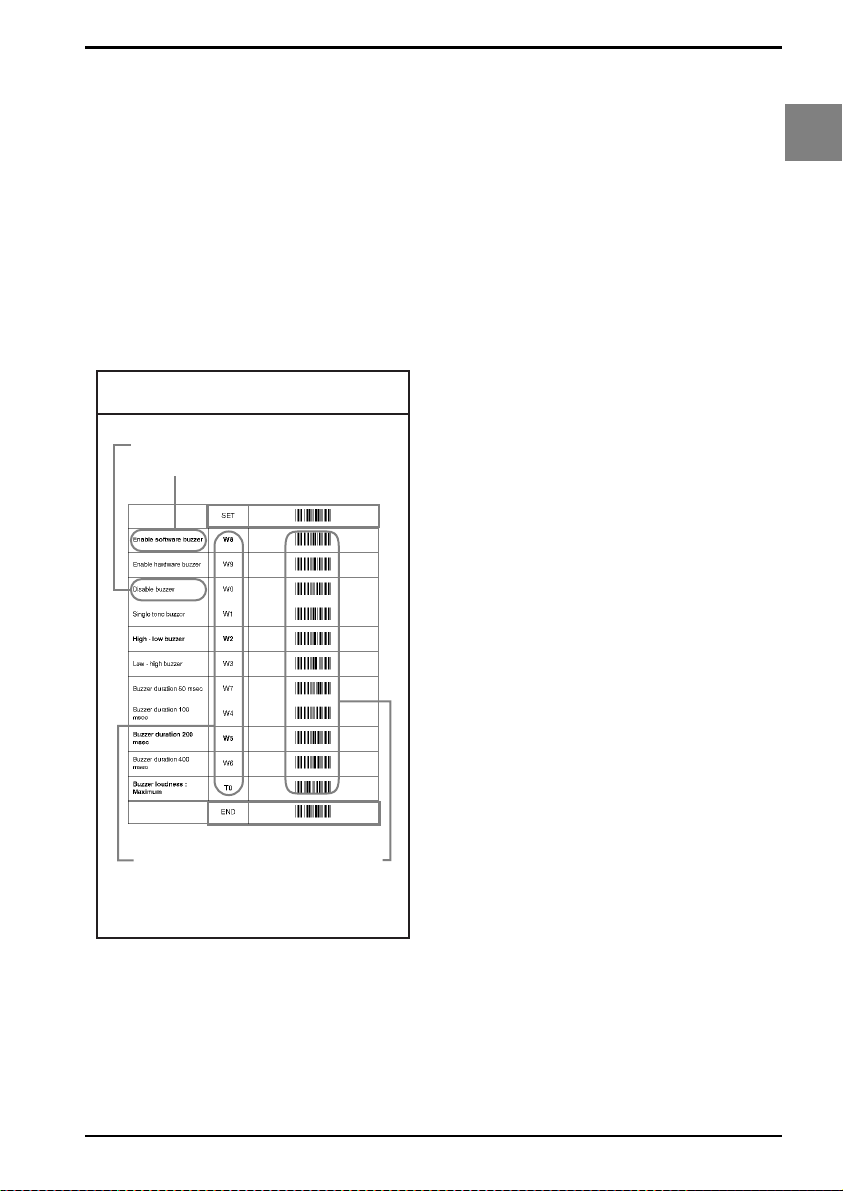
Menu labels
The reader must be set by reading the bar code
labels in the menu table. The layout of the table
is explained in next figure 0.01.
Fig. 0.01. Menu labels
optional setting
factory default setting
Enter mode
0
Introduction
Save mode
serial commands
Besides options, some chapters have
commands. The commands need to be
scanned directly , without reading the “SET” and
“END” labels. The commands are executed
directly and, unlike options, are not stored in
non volatile memory.
configuration parameters
U1
Page 8
OPTICON UNIVERSAL MENU BOOK
Configuring via the menu book
To configure the required options proceed as
follows:
• scan the SET label
• scan the required option(s)
• scan the END label
After scanning the END label, the new settings
are stored in non volatile memory.
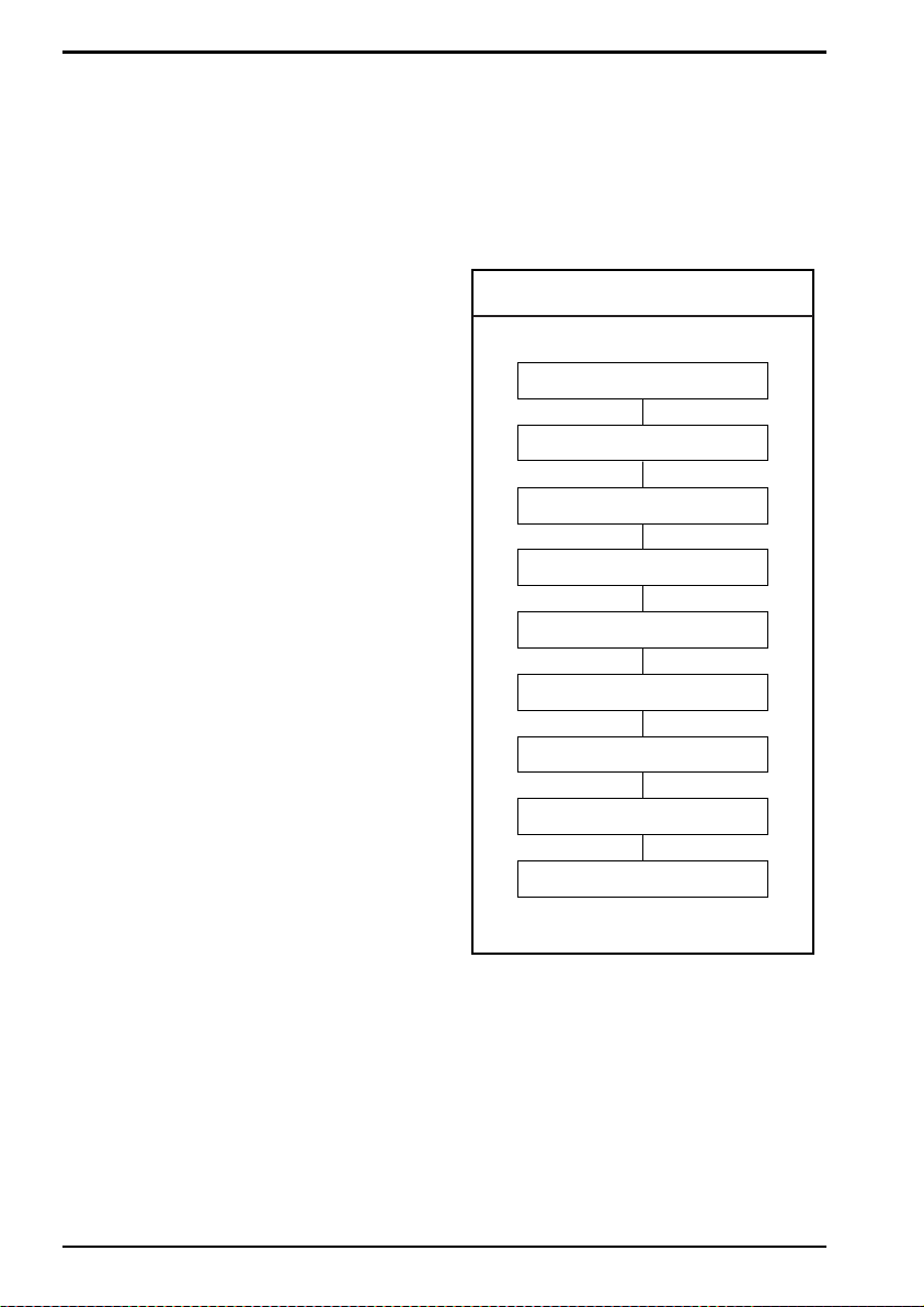
Recommended steps to follow for quick
configuration
After checking your connection you are ready
to start the configuration of your reader.
•6:
Use chapter 6 to select the indicator options
you prefer. These options affect the operation
of the buzzer and good read LED.
* The reader will now operate to your personal
preference.
See figure 0.02.
Fig. 0.02. Configuring via the menu book
• Check connection:
Ensure that the power is disconnected from
your equipment before you connect the reader.
After connecting the data cable, the power can
be applied to the equipment and the reader.
•1:
Use chapter 1 to set the correct default for your
reader.
* The reader is now in factory default.
•2:
Use chapter 2 to optimize the interface.
* The reader is now able to read bar codes and
transmit the data.
•3:
Use chapter 3 to optimize the reader for the
type of bar codes you use. Set the readable
codes first and then the options for each of
these codes.
* The reader is now able to read the codes you
selected, validate the data using length and
check digit and transmit that part of the data
you specified.
•4:
Use chapter 4 to select the string options for
your application. These include transmission of
code length, conversion of upper and lower
case and setting a prefix and suffix.
* The reader can now read and transmit the
data in the required format.
Power OFF
Connect reader
Power ON
Set Default
Optimize interface
Optimize symbologies
Set string options
Set read options
Set indicator options
•5:
Use chapter 5 to select the read options to your
preference. These options affect the read
mode, read time, trigger and redundancy.
U2
Page 9
OPTICON UNIVERSAL MENU BOOK
Configuring via RS232
In the middle column of the menu pages the
command is printed, e.g. U2. These commands
can be sent to readers with an RS232 interface.
To configure via the RS232 port proceed as
follows:
• transmit <ESC><Command string 1><CR>
• transmit <ESC><Command string 2><CR>
• transmit <ESC><Command string n><CR>
• transmit <ESC><Z2><CR>
<ESC>
<ESC> is the ASCII escape character (Hex
1B).
<Command string>
<Command string> is the ASCII command with
its parameters as would be scanned from the
menu book, i.e. <ESC>M41B<CR> configures
the ASCII control code <STX> as the prefix for
Code 39.
Example in hexadecimal format:
1B 4D 34 31 4B ØD
Each 3-character command should be
preceded with the '[' character (Hex 5B) i.e.
<Esc>[BCC<CR> is used to enable Data
Matrix.
Each 4-character command should be
preceded with the ']' character (Hex 5D) i.e.
<Esc>]DIAU<CR> is used to disable auto
connect.
<CR>
<CR> is the ASCII CR character (Hex ØD).
The characters transmitted must be separated
by an intercharacter delay to allow the reader to
process each character received and to
execute the command string.
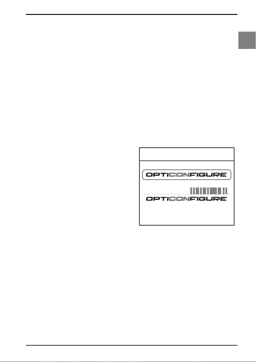
Configuring via OptiConfigure
OptiConfigure is the interactive Universal menu
book version. With OptiConfigure it is possible
to create your own personal setup sheet online. OptiConfigure supports Opticon bar code
readers which can be configured with this
Universal menu book. In addition OptiConfigure
offers product specific and less often used
menu labels. Based on the product and
software version selected, OptiConfigure will
show these specific options.
OptiConfigure can be accessed via the Opticon
home page (www.opticon.com). From there
select the OptiConfigure button.
Fig. 0.03. Opticonfigure
Set up your personal configuration
Universal menu book on-line
bar code configuration and commands application
0
Introduction
<Z2>
Some options are not immediately active, like
baud rate settings. Most other options are
immediately active, but the command Z2 must
be send to store the settings to non volatile
memory.
The following commands may be used to:
Command B sound a good read beep
Command E sound an error beep
Command L switch on good read LED
Command Y de-trigger the reader
Command Z trigger the reader
U3
Page 10

OPTICON UNIVERSAL MENU BOOK
U4
Page 11

OPTICON UNIVERSAL MENU BOOK
1. DEFAULTS
This option allows you to undo all previously
configured options and bring the reader's
configuration back to factory default settings.
These factory default settings are printed in
bold.
Note that differences may occur depending on
the type of interface as will be mentioned in the
text.
Select only the correct default settings
corresponding to your hardware "defaults"
label.
The interfaces supported depend on the reader
model and software release.
Please consult your sales office for not listed
interfaces.
1
Defaults
U5
Page 12

1. Defaults
OPTICON UNIVERSAL MENU BOOK
RS232
Serial TTL
AT wedge
USB
Bluetooth
IEEE 802.15.4
SET
U2
SS
UB
SU
SO
SM
END
_ZZ_
_U2_
_SS_
_UB_
_SU_
_SO_
_SM_
_ZZ_
U6
Page 13

OPTICON UNIVERSAL MENU BOOK
2. INTERFACE
This chapter describes the configurable
transmission options for your reader. Some
options may not be relevant to the type of
reader you have. An attempt to configure the
reader for such options does not affect its
operation and usually results in the reader
producing an error tone, indicating you tried to
make an illegal configuration entry.
2
Interface
U7
Page 14
OPTICON UNIVERSAL MENU BOOK
2.1. RS232 options
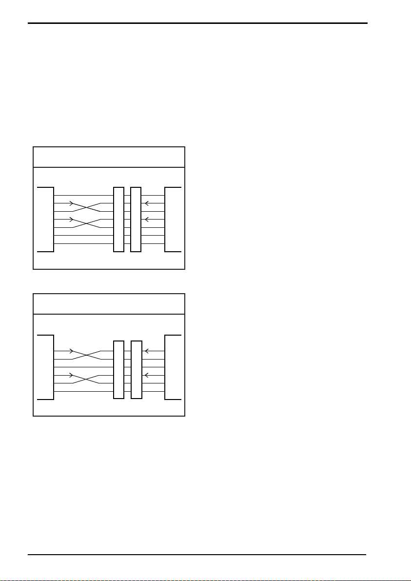
This paragraph describes the specific options
for a reader with an RS232 interface.
Bar code readers with an RS232 interface are
normally supplied with either a DB25 or DB9
female connector. Both connectors are fitted
with an external power connector. See figure
2.01 or 2.02.
Fig. 2.01. RS232 options DB25
DB25S
DB25P
FG
TxD
RxD
RTS
CTS
SG
SCANNER
+5V
1
2
3
4
5
7
25
Fig. 2.02. RS232 options DB9
DB9S
TxD
RxD
SG
RTS
CTS
SCANNER
+5V
3
2
5
7
8
9
1
2
3
4
5
7
25
DB9P
3
2
5
7
8
9
FG
TxD
RxD
RTS
CTS
SG
+5V
TxD
RxD
SG
RTS
CTS
+5V
HOST
HOST
TxD:
Transmitted Data: Transmits data from the
reader to the host. This connection is
mandatory.
RxD:
Received Data: Receives data from the host to
the reader. This connection is required if you
want to send commands to the bar code reader
or if software handshaking or
acknowledgement control is used.
RTS:
Request To Send: A general purpose output to
the host, used for hardware flow control. This
connection is optional.
CTS:
Clear To Send: A general purpose input to the
bar code reader, used for hardware flow
control. This connection is optional.
SG:
Signal Ground: Reference point for power
supply and interface signals. This connection is
mandatory.
+5V:
5 Volt power supply to the reader. This pin is
disconnected when the external power
connector is in use.
Other connectors and/or connections are
available by special order.
Pin functions as seen from the bar code reader.
FG:
Frame Ground: This is normally connected to
the "chassis ground" at the host computer. In
the RS232 specification the use of FG is
optional.
U8
Page 15
OPTICON UNIVERSAL MENU BOOK
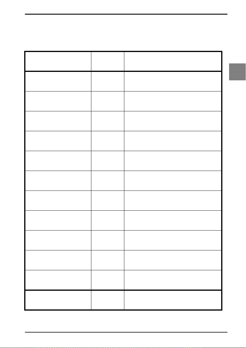
2.1.1. Baud rate settings The baud rate is the rate at which bits are
transmitted from the reader to the host, and
vice versa. Both the reader and the host should
be set to the same baud rate
150 baud
300 baud
600 baud
1200 baud
2400 baud
4800 baud
9600 baud
19200 baud
SET
K0
K1
K2
K3
K4
K5
K6
K7
_ZZ_
_K0_
_K1_
_K2_
_K3_
_K4_
_K5_
_K6_
_K7_
2
Interface
38400 baud
57600 baud
115200 baud
K8
K9
SZ
END
_K8_
_K9_
_SZ_
_ZZ_
U9
Page 16

2.1.2. Data, parity and stop bits
OPTICON UNIVERSAL MENU BOOK
The data characters may be transferred in one
of the following formats:
A parity bit may be added to every character so
that the total number of 1's in the data bits,
together with the parity bit, is odd for odd parity
or even for even parity. See figure 2.03.
SET
7 data bits
8 data bits
No parity
L0
L1
L2
Fig. 2.03. Data, parity, stop bits
(1)
START
(2)
START
(3)
START
(4)
START
(5)
START
(6)
START
(7)
START
(8)
START
7 Bit Data
7 Bit Data
7 Bit Data
7 Bit Data
8 Bit Data
8 Bit Data
8 Bit Data
8 Bit Data
_ZZ_
_L0_
_L1_
_L2_
STOP
2 STOP
PARITY
PARITY
STOP
2 STOP
STOP
2 STOP
PARITY STOP
PARITY
2 STOP
Even parity
Odd parity
1 stop bit
2 stop bits
L3
L4
L5
L6
END
_L3_
_L4_
_L5_
_L6_
_ZZ_
U10
Page 17
OPTICON UNIVERSAL MENU BOOK
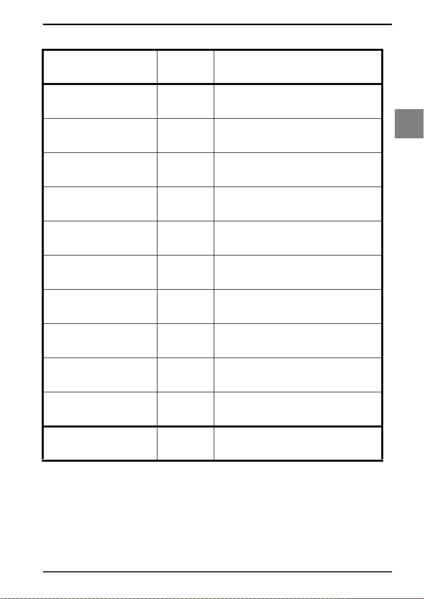
2.1.3. Handshaking
Data flow control is available using either
hardware (Modem, Busy/Ready) or software
(XON/XOFF). In addition, an optional
acknowledgement control is available (ACK/
NAK with or without error response). Flow
control may be combined with
acknowledgement control. The RS232 voltage
levels employed by most readers for
transmission are either -10V (OFF) or +10V
(ON).
1. No handshake:
Does not employ any handshaking: data is
transmitted regardless of the control signals.
This option will undo any handshake and flow
control options selected.
2. Busy/ready:
The reader's RTS is ON as soon as the power
is supplied to the reader and will stay ON while
the reader can receive data from the host. The
host will keep the reader's CTS ON while it is
ready to receive data from the reader. While
CTS is ON the reader is able to transmit data.
The reader will abort transmission with an error
indication of the buzzer when the CTS is not
ON within a certain configurable period. The
reader may drop RTS to OFF during
transmission if it can not receive data
simultaneously. See figure 2.04.
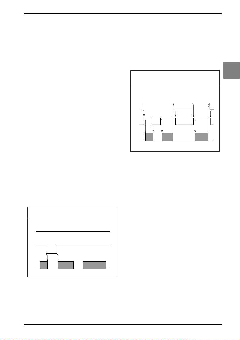
Fig. 2.04. HandShaking
Busy/ready
ON the reader is allowed to transmit data.
When all data has been transmitted, the reader
will turn RTS OFF. In response, the host should
turn OFF the reader's CTS. If, while RTS is ON,
the CTS line is not ON for a certain
configurable period, the reader will terminate
the transmission with an error indication of the
buzzer. See figure 2.05.
Fig. 2.05. HandShaking
Modem mode
RTS
CTS
TxD
ON
OFF
ON
OFF
ON
OFF
4. XON/XOFF:
The reader sends data until an XOFF (ASCII
DC3, Hex 13) character is received from the
host. Only when the reader receives an XON
(ASCII DC1, Hex 11) character, the reader
continues to send its data.
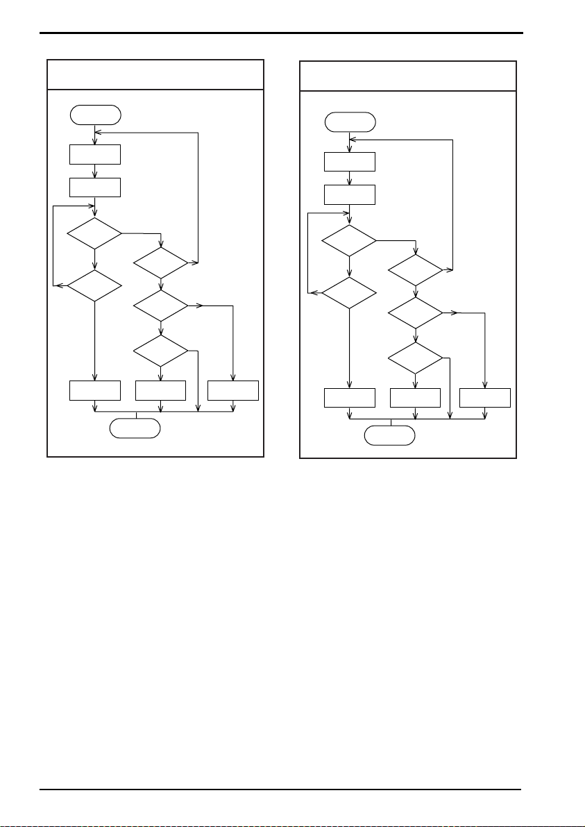
5. ACK/NAK:
After data has been transmitted, the reader
expects to receive one of the following
responses from the host:
2
Interface
RTS
CTS
TxD
ON
OFF
ON
OFF
ON
OFF
3. Modem mode:
The reader's RTS is OFF as soon as power is
supplied to the reader. The reader will turn RTS
ON when it wants to transmit data to the host.
The host should respond by putting CTS ON
when it is ready to receive data. While CTS is
Response: "ACK" (ASCII: Hex Ø6)
Action: The reader completes transmission with
the good-read buzzer.
Response: "NAK" (ASCII: Hex 15)
Action: The reader sends the data again.
Response: "DC1" (ASCII: Hex 11)
Action: The reader completes transmission
without a good-read or error buzzer.
Response: "None"
Action: If there is no response within one
second then the reader terminates
transmission with an error buzzer. See figure
2.06.
U11
Page 18
OPTICON UNIVERSAL MENU BOOK
Fig. 2.06. HandShaking
Start of
transmission
Transmit
data
Start 1 sec.
timer
Answer
received
No
No
Timer
ended
Yes
ERROR
Buzzer
END
ACK/NAK
Yes
Answer
= NAK
No
Answer
= ACK
No
Answer
= DC1
No
ERROR
Buzzer
Fig. 2.07. HandShaking
ACK/NAK no response
Start of
transmission
Transmit
data
Start 1oo ms.
timer
Answer
Yes
received
No
No
Timer
ended
Yes
GOOD READ
Buzzer
Yes
Yes
Yes
GOOD READ
Buzzer
END
Answer
= NAK
Answer
= ACK
Answer
= DC1
ERROR
Buzzer
Yes
No
Yes
No
Yes
No
GOOD READ
Buzzer
6. ACK/NAK no response:
The difference from the ACK/NAK mode is that
when no response from the host is received
within 100 ms, the reader assumes that the
data has been received correctly by the host.
Response: "ACK" (ASCII: Hex Ø6)
Action: The reader completes transmission with
the good-read buzzer.
Response: "NAK" (ASCII: Hex 15)
Action: The reader sends the data again.
Response: "DC1" (ASCII: Hex 11)
Action: The reader completes transmission
without a good-read or error buzzer.
Response: "None"
Action: If there is no response within 100 ms
then the reader terminates transmission with a
good read buzzer. See figure 2.07.
U12
Page 19
2.1.3. Handshaking
OPTICON UNIVERSAL MENU BOOK
No handshake
Busy/ready
Modem
XON/XOFF
ACK/NAK
ACK/NAK NO
RESPONSE
Flow Control time out
indefinitely
Flow Control time out
100ms
SET
P0
P1
P2
ZG
P3
P4
I0
I1
_ZZ_
_P0_
_P1_
_P2_
_ZG_
_P3_
_P4_
_I0_
_I1_
2
Interface
Flow Control time out
200ms
Flow Control time out
400ms
I2
I3
END
_I2_
_I3_
_ZZ_
U13
Page 20

OPTICON UNIVERSAL MENU BOOK
2.1.4. Intercharacter delay for RS232
The intercharacter delay introduces a
configurable time delay after each character
transmitted. This may be used if the connected
computer or terminal does not support flow
control and is not capable of handling the
received data.
No delay
20 ms delay
50 ms delay
100 ms delay
SET
KA
KB
KC
KD
END
_ZZ_
_KA_
_KB_
_KC_
_KD_
_ZZ_
U14
Page 21
OPTICON UNIVERSAL MENU BOOK
2.2. Keyboard wedge/USB options
This paragraph describes the options which are
relevant to readers with a wedge or USB
interface. The following parameters can be
configured:
• keyboard language
• special options
• intercharacter delay
Because these options are interdependent, it is
important to perform the configuration in the
sequence given.
Please consult your sales office for keyboard
layouts and language currently supported.
With keyboard:
Use this mode in case a keyboard is connected
to the PC wedge Y-cable.
The wedge is only listening in case the
computer is booting or when the wedge is idle.
Without keyboard:
Use this mode in case no keyboard is
connected to the PC wedge Y-cable. In some
cases this mode is required in case only a PC
USB keyboard is connected. If this option is
enable, the computer can detect the wedge as
a keyboard. In case the computer reports a
keyboard error or in case no data is displayed,
try this option. It is required to power OFF the
PC, wait 10 seconds and power ON the PC
again. Do not enable this option in case a
keyboard is connected to the Y-cable.
2
Interface
Keyboard wedge operation modes:
This mode enables or disables responses from
PC wedge to the computer during booting.
In normal cases, the keyboard handles the
responses to the computer. The PC wedge is
only listening in order to be aware of the
keyboard state.
SET
With keyboard
Without keyboard
KM
KL
END
The wedge is responding to all commands from
the computer.
The ‘without keyboard’ option is only supported
for PC/AT wedges.
_ZZ_
_KM_
_KL_
_ZZ_
U15
Page 22

OPTICON UNIVERSAL MENU BOOK
2.2.1. Keyboard language
Keyboards are also different depending on
country or language. Examples are the
QWERTY and AZERTY keyboards. Select the
same language that has been selected on your
PC.
The languages supported depend on the
reader model and software release. Please
consult your sales office for the languages
currently supported.
US
UK
German
French
Italian
Spanish
Portuguese
Swiss ( French )
SET
KE
KV
KG
KI
OW
KJ
PH
PL
_ZZ_
_KE_
_KV_
_KG_
_KI_
_OW_
_KJ_
_PH_
_PL_
Swiss ( German )
PK
END
_PK_
_ZZ_
U16
Page 23

OPTICON UNIVERSAL MENU BOOK
Dutch
Belgian
Swedish
Finnish
Danish
Norwegian
Japanese
Czech
SET
PI
PJ
PD
PG
KK
PE
PM
WF
_ZZ_
_PI_
_PJ_
2
Interface
_PD_
_PG_
_KK_
_PE_
_PM_
_WF_
END
_ZZ_
U17
Page 24

OPTICON UNIVERSAL MENU BOOK
2.2.2. Special options
This section contains some specialised
keyboard options.
Do not use numpad:
The reader wil emulate the numerical keys on
the alpha keypad when transmitting numerical
data.
Use numpad:
The reader will emulate the numerical keypad
when transmitting numerical data. The
NUMLOCK should always be ON when this
option has been selected.
Auto NumLock mode:
When selecting this option, the bar code reader
automatically uses the correct NumLock state.
No CAPSLOCK mode:
This options cancels the CAPSLOCK mode.
CAPSLOCK mode:
This option ensures that data is displayed
correctly when the keyboard is normally in
CAPSLOCK mode. The keyboard is returned in
the CAPSLOCK mode after transmission.
Auto CAPSLOCK mode:
When selecting this option, the transmitted data
is displayed correctly, disregarding the
CAPSLOCK state.
Do not use numpad
Use numpad
Auto numlock mode
No CAPSLOCK mode
CAPSLOCK mode
Auto CAPSLOCK mode
SET
RN
RM
/A
5Q
8A
2U
END
_ZZ_
_RN_
_RM_
_/A_
_5Q_
_8A_
_2U_
_ZZ_
U18
Page 25

OPTICON UNIVERSAL MENU BOOK
2.2.3. Intercharacter delay for wedges/USB
The intercharacter delay can be used to adapt
the reader's data transmission speed to the
system. If the transmission speed is too high,
the system may not be able to receive all
characters. Adjust the intercharacter delay until
the data is received correctly.
The default value as well as the actual delay
time depend on the terminal type and language
selected.
2
Interface
U19
Page 26

OPTICON UNIVERSAL MENU BOOK
2.2.3. Intercharacter delay for wedges/USB
No delay
Delay = 1
Delay = 2
Delay = 3
Delay = 4
Delay = 5
Delay = 6
Delay = 7
SET
LA
LB
LC
LD
LE
LF
LG
LH
_ZZ_
_LA_
_LB_
_LC_
_LD_
_LE_
_LF_
_LG_
_LH_
Delay = 8
Delay = 9
Delay = 10
LI
LJ
LK
END
_LI_
_LJ_
_LK_
_ZZ_
U20
Page 27

OPTICON UNIVERSAL MENU BOOK
2.3. Wireless options
This section is intended to configure a wireless
connection to an Opticon cradle and third party
dongles. Options are available to minimize the
reader’s power consumption and to maximize
working time and enable secure data
exchange.
Default Bluetooth connection:
By default the reader is configured to connect
to the Opticon cradle. Simply read the twelve
character Bluetooth address label on the
bottom of the cradle. The reader automatically
connects to the cradle and automatically
configures the pin code, authentication and
encryption.
Default IEEE 802.15.4 connection:
By default the reader is configured to connect
to the Opticon cradle. Simply read the tencharacter address label on the bottom of the
cradle. The reader automatically connects to
the cradle and automatically configures the pin
code, authentication and encryption.
With IEEE 802.15.4, the connection only exists
during data transfers. Therefor the options
"Auto disconnect" and "Auto reconnect" are not
supported.
DRS232 cradle connection:
In case the cradle is connected to the computer
via RS232, the communication parameters
such as baud rate, data bits, parity and stop
bits can be configured via the bar code reader.
For baud rate settings and for data, parity and
stop bits refer to the applicable paragraphs as
described earlier in this chapter.
need this information to configure the bar code
reader. The Bluetooth dongle's driver installs a
serial port on the computer, which is used by
the bar code reader to transmit the data.
Keyboard emulation:
In case keyboard emulation is required,
Opticon's program Tscan can convert the serial
data from a COM port into keyboard data. Ask
your local dealer or sales office how to obtain
Tscan.
Enable auto connect to Opticon cradle:
After reading the address label on the cradle,
the reader immediately tries to establish a
connection.
Disable auto connect to Opticon cradle:
After reading the address label on the cradle,
the reader needs to be connected manually.
Connect to other Bluetooth device:
In order to connect to a different Bluetooth
device scan the applicable menu labels in the
following configuration order:
• set Bluetooth device address (mandatory)
• set Security (optional)
• read label: Manually connect (mandatory)
Bluetooth options:
The reader can be configured for several
options:
• set connection (mandatory), choose from
trigger connection or auto connection
• select an address (mandatory)
• select security method (optional)
• set power savings (optional)
• select memorizing options (optional)
2
Interface
USB cradle connection:
In case the cradle is connected to the computer
via USB, the USB driver for the cr adle needs to
be installed. This driver can be downloaded
from www.opticon.com. The USB driver installs
a serial port on the computer. Please consult
your sales office for not listed platforms.
Bluetooth dongle connection:
In case a third party Bluetooth dongle is used,
the Bluetooth address, pin code and security
options needs to be configured manually.
Consult your Bluetooth dongle manual how to
obtain the Bluetooth address, how to configure
the pin code and secure transmission. You
IEEE 802.15.4 options:
The reader can be configured for several
options:
• set connection (mandatory)
• set trigger connect options (optional)
• set power savings (optional)
• select memorizing options (optional)
U21
Page 28

OPTICON UNIVERSAL MENU BOOK
2.3.1. Bluetooth address
T o enable the Bluetooth reader to communicate
to another Bluetooth device, the Bluetooth
address of that device must be configured in
the reader.
The Bluetooth address can be found on the
other device. Mostly it is displayed on the
product label as a 12 digits number or a
number with 6 hex digit pairs.
To configure an Opticon Bluetooth bar code
reader to connect to a third party Bluetooth
dongle, the following steps must be taken:
• step 1 - retrieve the dongle’s MAC address
• step 2 - set the reader to connect directly to a
computer
• step 3 - set the MA C address of the dongle in
the reader
• step 4 - establish connection to the Bluetooth
module
Example for manually connection and
configuration:
Example Step 1.
The following information is retrieved from the
dongle's Bluetooth manager:
Dongle make/type: MSI MS6967
Bluetooth Address: 00 04 12 34 AF 56
Secure Connection: Not Required.
Example Step 2.
• read the following codes:
<SET>
<Connect to PC>
Example Step 3.
Note: when reading the same menu label
again, it is necessary to keep the reader away
from the menu book for about one second.
• from this chapter read:
<Set bluetooth address label>
• from the chapter Direct input numeric read:
<0>
keep reader away from menu book...
<0>
keep reader away from menu book...
<0>
<4> <1> <2> <3> <4>
• from the chapter Direct input character read:
<A> <F>
• from the chapter Direct input numeric read:
<5> <6>
• from this chapter read:
<End bluetooth address label>
<END>
Example Step 4.
• read the command label:
<Manually connect>
Commands for (dis)connection:
In case a Bluetooth address is already
configured, the reader can be manually
connected or disconnected with the
following command labels:
• connection: <Manually connect>
• disconnection: <Manually disconnect>
U22
Page 29
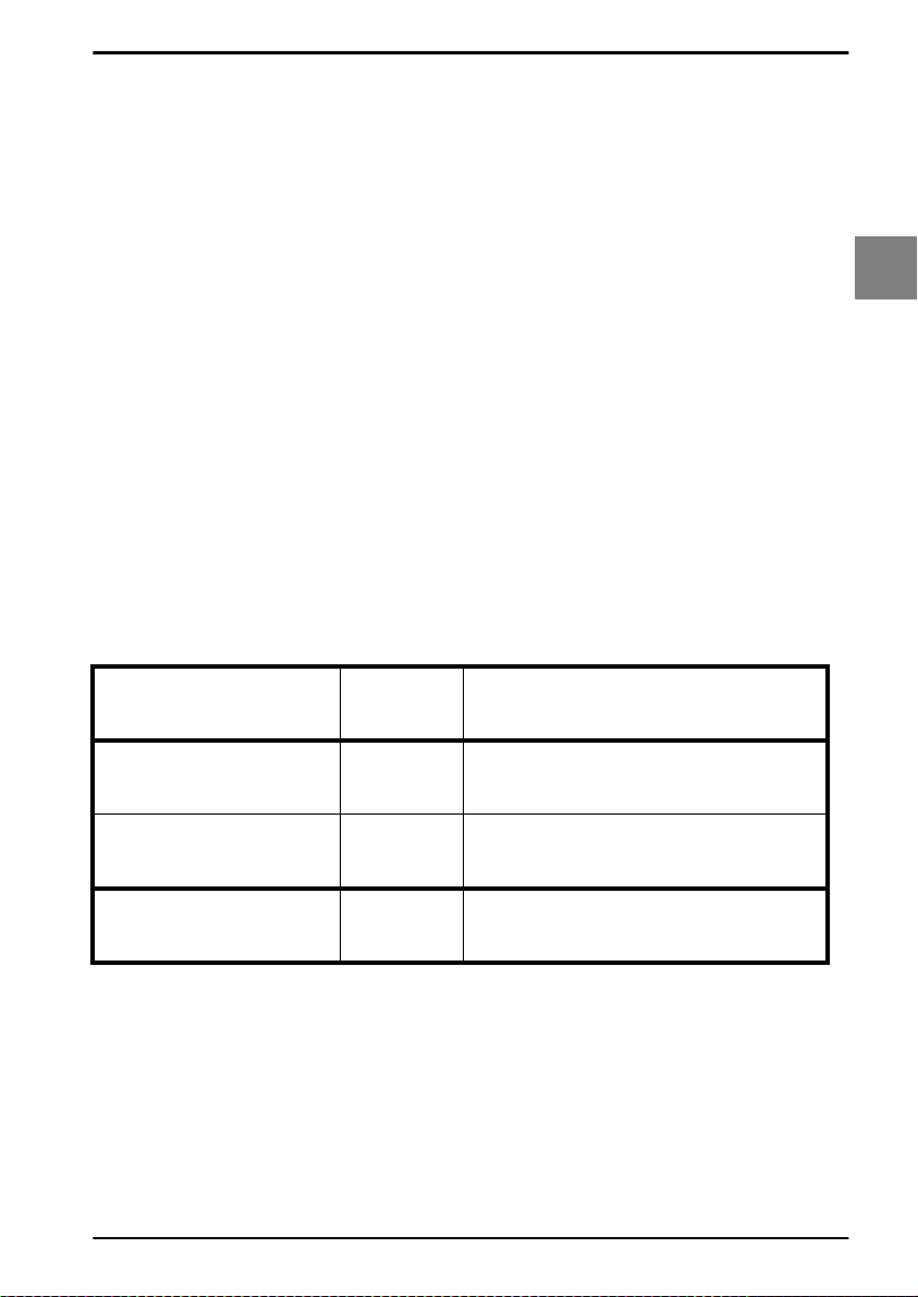
2.3.1. Bluetooth address
OPTICON UNIVERSAL MENU BOOK
Set bluetooth address
label
End bluetooth address
label
Disable auto connect
Enable auto connect
Connect to PC
Connect to Cradle
2.3.1. Bluetooth address commands
BDAS
BDAE
DIAU
ENAU
CNPC
CNCR
SET
END
_ZZ_
_BDAS_
_BDAE_
_DIAU_
_ENAU_
_CNPC_
_CNCR_
_ZZ_
2
Interface
Manually disconnect
Manually connect +-CONN-+
+-DISC-+
_+-DISC-+_
_+-CONN-+_
U23
Page 30

OPTICON UNIVERSAL MENU BOOK
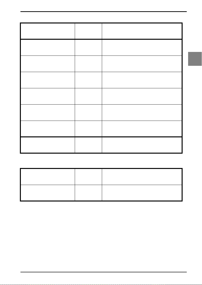
2.3.2. Bluetooth security
To provide additional security connections, the
Bluetooth specification allows you to enable a
special security setting, so that a PIN-code is
required from the bar code reader in order to
establish a connection.
Use 'secured' connections
If you want to use 'secured' connections:
• scan enable authentication label
• scan the PIN-code labels. The PIN-code is a
code of 1 to 16 characters. Any personal
combination alpha-numeric characters can
be used. Read direct input (numeric)
characters from the chapter: String options
• enable authentication on the host
• if encryption is required, scan enable
encryption labels
Use 'unsecured' connections
If you want to use 'unsecured' connections:
• scan disable authentication labels
• disable authentication on the host
Set PIN-code label
End PIN-code label
Authentication if not
paired
Disable authentication
Enable authentication
Disable encryption
Enable encryption
SET
PINS
PINE
AUTO
AUTD
AUTE
ENCD
ENCE
END
_ZZ_
_PINS_
_PINE_
_AUTO_
_AUTD_
_AUTE_
_ENCD_
_ENCE_
_ZZ_
U24
Page 31
OPTICON UNIVERSAL MENU BOOK
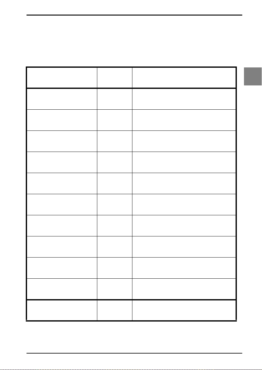
2.3.3. Trigger connection options
Press trigger switch time to connect:
This is the time the trigger switch needs to be
pressed where after the reader tries to
establish a connection.
Disabled
1 second
2 seconds
3 seconds
4 seconds
5 seconds
6 seconds
7 seconds
SET
PC00
PC01
PC02
PC03
PC04
PC05
PC06
PC07
_ZZ_
_PC00_
_PC01_
_PC02_
_PC03_
_PC04_
_PC05_
_PC06_
_PC07_
2
Interface
8 seconds
9 seconds
PC08
PC09
END
_PC08_
_PC09_
_ZZ_
U25
Page 32

OPTICON UNIVERSAL MENU BOOK
2.3.4. Trigger disconnect options
Press trigger switch time to disconnect:
This is the time the trigger switch needs to be
pressed where after the reader disconnects.
Disabled
1 second
2 seconds
3 seconds
4 seconds
5 seconds
6 seconds
7 seconds
SET
PD00
PD01
PD02
PD03
PD04
PD05
PD06
PD07
_ZZ_
_PD00_
_PD01_
_PD02_
_PD03_
_PD04_
_PD05_
_PD06_
_PD07_
8 seconds
9 seconds
PD08
PD09
END
_PD08_
_PD09_
_ZZ_
U26
Page 33
OPTICON UNIVERSAL MENU BOOK
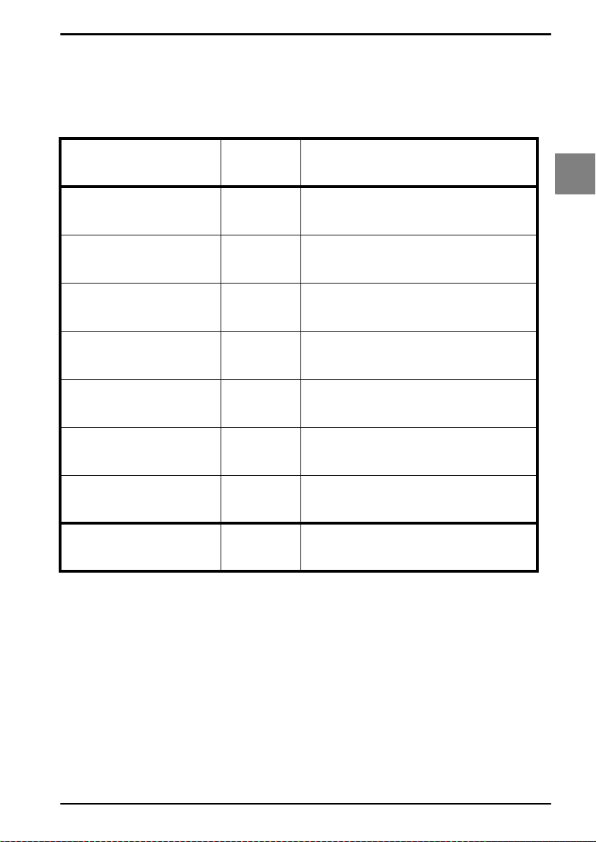
2.3.5. Auto disconnect options
Auto disconnect:
If the reader is idle for the configured time, it will
disconnect. Purpose options are power saving.
Disabled
10 minutes
20 minutes
30 minutes
40 minutes
50 minutes
60 minutes
SET
AD00
AD01
AD02
AD03
AD04
AD05
AD06
END
_ZZ_
2
Interface
_AD00_
_AD01_
_AD02_
_AD03_
_AD04_
_AD05_
_AD06_
_ZZ_
U27
Page 34

OPTICON UNIVERSAL MENU BOOK
2.3.6. Auto reconnect options
Auto reconnect:
If the reader is disconnected because it is out
of range or the Bluetooth device is not
available, the reader will try to establish the
connection during the configured time. If this
time is expired, the reader stops trying. The
reader will not reconnect after reading the
manually disconnect label or after auto
disconnection.
Disabled
1 minute
2 minutes
3 minutes
4 minutes
5 minutes
6 minutes
7 minutes
SET
CA00
CA01
CA02
CA03
CA04
CA05
CA06
CA07
_ZZ_
_CA00_
_CA01_
_CA02_
_CA03_
_CA04_
_CA05_
_CA06_
_CA07_
8 minutes
9 minutes
CA08
CA09
END
_CA08_
_CA09_
_ZZ_
U28
Page 35
OPTICON UNIVERSAL MENU BOOK
2.3.7. Wireless power saving
Activation levels:
In order to reduce the power consumption it is
possible to set the activity rate of the reader.
The default setting is ‘Active’, meaning that the
reader will continuously check for
communication. By setting the level to a certain
time the reader will reduce activity and check
for communication only at the set time.
Auto disconnect:
Power consumption can also be reduced by
auto disconnect settings as described in the
chapters: Auto disconnect options and Auto
reconnect options.
2
Interface
Level 0
Level 1 300 slots,
187.5ms
Level 2 500 slots,
312.5ms
Level 3 700 slots,
437.0ms
Level 4 900 slots,
562.5ms
Level 5 1100 slots,
687.5ms
Level 6 1300 slots,
812.5ms
Level 7 1500 slots,
937.5ms
SET
LV00
LV01
LV02
LV03
LV04
LV05
LV06
LV07
_ZZ_
_LV00_
_LV01_
_LV02_
_LV03_
_LV04_
_LV05_
_LV06_
_LV07_
END
_ZZ_
U29
Page 36

OPTICON UNIVERSAL MENU BOOK
2.3.8. Memorizing
Memorizing options can be used to temporary
store bar code data in case the bar code reader
lost its connection. As soon the reader is
connected again, the temporary stored data is
transmitted to the computer and the storage
area is cleared.
The data is stored in RAM. In case the battery
is depleted or battery is removed, data is lost.
The bar code reader is automatically
disconnected in case:
• the bar code reader is out of range ( too far
away from cradle ),
• power from cradle is lost.
Data memorizing disabled:
Bar code data is not stored automatically, in
case the connection is lost. Data memorizing
can manually be started by reading the Start/
continue memorizing option.
Data memorizing enabled:
Bar code data is stored automatically, in case
the connection is lost.
Memorize after connection loss:
Data is only temporary stored in case the bar
code reader lost its connection. Memorizing
stops in case the +-DISC-+ label is read or in
case the wireless address is changed.
Clear all memorized data:
All memorizing data is deleted and the storage
area is cleared.
Available memory for memorizing is reader
dependent ( 12kB )
Always memorize when not connected:
Data is always temporary stored in case the bar
code reader is not connected.
Memorize control labels:
The next options should be used without
reading the SET and END label. These
memorizing options are intended to manually
control the memorizing mode.
Start/continue memorizing:
Manually start memorizing. In case memorized
data was present, it will continue memorizing.
Stop/pause memorizing:
Manually stop memorizing. Memorizing can be
continued by reading the Start/continue
memorizing option.
U30
Page 37
2.3.8. Memorizing
OPTICON UNIVERSAL MENU BOOK
SET
Data memorizing
disabled
Data memorizing
enabled
Memorize after
connection loss
Always memorize when
not connected
2.3.8. Memorizing commands
Clear all memorized data +-MCLR-+
Start/continue
memorizing
DTMD
DTME
BM0
BM1
END
+-MSTR-+
_ZZ_
_DTMD_
_DTME_
_BM0_
_BM1_
_ZZ_
_+-MCLR-+_
_+-MSTR-+_
2
Interface
Stop/pause memorizing +-MSTP-+
_+-MSTP-+_
U31
Page 38

OPTICON UNIVERSAL MENU BOOK
U32
Page 39

OPTICON UNIVERSAL MENU BOOK
3. CODE OPTIONS
The menu options in this chapter are intended
to select:
• which bar code types can be read
• the permissible length of the bar codes to be
read
• bar code specific options
In short: the decoding characteristics of the
reader can be adjusted.
3
Code options
U33
Page 40
OPTICON UNIVERSAL MENU BOOK
3.1. Setting of readable codes
3.1.1. Enabling a single read. code
These options do not affect the reading of the
menu labels. The required bar code types can
be selected by enabling a single readable code
only and enabling readable codes.
It is strongly recommended to select only
the required codes.
Advantages of selecting only the required
codes are:
• faster reading
• no accidental scanning of unwanted bar
codes
• reduced probability of reading errors which
can not be prevented completely, because of
the limited security of some bar code types
Some bar codes are translations or special
variants of other bar code types. The next
figure lists their relationships. See figure 3.01.
Example:
To read Italian Pharmaceutical type bar codes,
Enable Code 39, Select the option 'Italian
Pharmaceutical' from the 'Options for Code 39'.
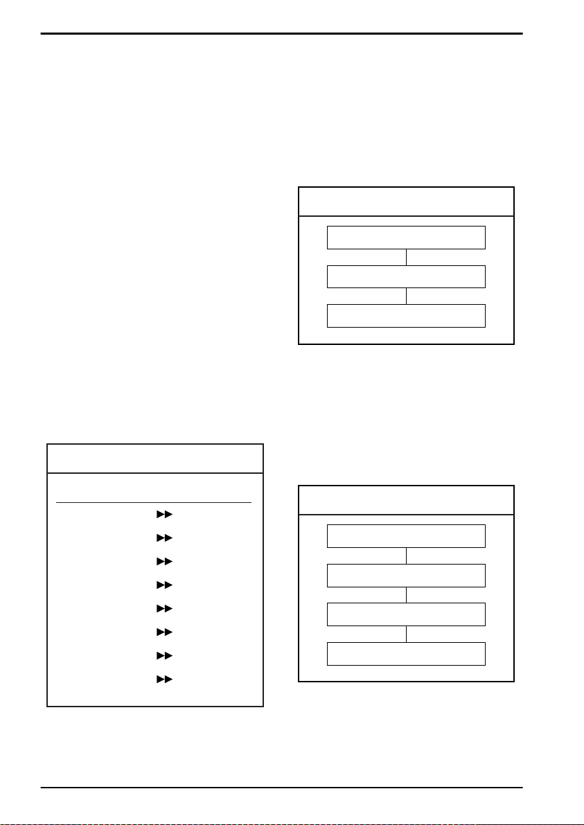
Fig. 3.01. Setting of readable codes table
RELATIONS
With this option you can set the reader to read
a single bar code type only. If you select 'Code
39 only', no other codes will be read.
Example:
If you want to read Code 39 only, you read the
option 'Code 39 only'. See figure 3.02.
Fig. 3.02. Enabling a single readable code:
Code 39
SET
Code 39 only
END
Example:
If you want to read one of the special bar codes
as listed in the relations table for setting of
readable codes, e.g. EAN128 only, you read
the option 'Code 128 only' followed by 'Enable
EAN-128 only' from the 'Options for Code 128'.
See figure 3.03.
Code type:
ABC Code
Code 39 Full ASCII
CX Code
EAN 128
ISBN Bookland
ISSN
ISMN
Tri-Optic
Belongs to:
Codabar
Code 39
Codabar
Code 128
EAN-13
EAN-13
EAN-13
Code 39
Fig. 3.03. Enabling a single readable code:
Code 128
SET
Code 128 only
Enable EAN-128 only
END
U34
Page 41
OPTICON UNIVERSAL MENU BOOK
3.1.1. Enabling a single read. code
All codes excl. add-on
Only all UPC and EAN
codes
UPC only
UPC + 2 only
UPC + 5 only
EAN only
EAN + 2 only
EAN + 5 only
SET
A0
J0
J1
J2
J3
J4
J5
J6
_ZZ_
_A0_
_J0_
_J1_
_J2_
_J3_
_J4_
_J5_
_J6_
3
Code options
Code 39 only
Tri-Optic only
Codabar only
Industrial 2of5 only
Interleaved 2of5 only
A2
JD
A3
J7
J8
END
_A2_
_JD_
_A3_
_J7_
_J8_
_ZZ_
U35
Page 42

OPTICON UNIVERSAL MENU BOOK
S-Code only
Matrix 2of5 only
Chinese Post Matrix 2of5
only
Korean Postal Authority
code only
IATA only
MSI/Plessey only
Telepen only
UK/Plessey only
SET
RA
AB
JE
JL
A4
A7
A9
A1
_ZZ_
_RA_
_AB_
_JE_
_JL_
_A4_
_A7_
_A9_
_A1_
Code 128 only
Code 93 only
Code 11 only
RSS-14 only
RSS-limited only
A6
A5
BLB
J9
JJ
END
_A6_
_A5_
_BLB_
_J9_
_JJ_
_ZZ_
U36
Page 43
OPTICON UNIVERSAL MENU BOOK
RSS-expanded only
DataMatrix ECC000 140 only
DataMatrix ECC200 only
Aztec only
Aztec runes only
QR Code only
Maxicode only
PDF417 only
SET
JK
BG2
BC0
BC5
BF4
BC1
BC2
BC3
_ZZ_
_JK_
_BG2_
_BC0_
3
Code options
_BC5_
_BF4_
_BC1_
_BC2_
_BC3_
MicroPDF417 only
Enable all 1D codes only
Enable all 2D codes only
BC4
BCA
BCB
END
_BC4_
_BCA_
_BCB_
_ZZ_
U37
Page 44
OPTICON UNIVERSAL MENU BOOK
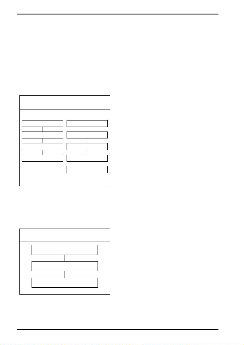
3.1.2. Enabling of readable codes
With this option you can set the reader to read
a number of bar code types or simply enable
additional bar code types.
Example:
If you only want to read Code 39 and Code
128, you read 'Code 39 only' and 'enable Code
128'. Alternatively you can read 'Disable All',
'Enable Code 39' and 'Enable Code 128'. See
figure 3.04.
Fig. 3.04. Enabling of readable codes
SET
Code 39 only
Enable Code 128
END
SET
Disable All
Enable Code 39
Enable Code 128
END
Example:
If you want to enable Codabar in addition to
what you already have configured, you read
'Enable Codabar'. See figure 3.05.
Fig. 3.05. Enabling of readable codes
addition
SET
Enable Codabar
END
U38
Page 45
OPTICON UNIVERSAL MENU BOOK
3.1.2. Enabling of readable codes
All codes excl. add-on
Enable UPC
Enable UPC + 2
Enable UPC + 5
Enable EAN
Enable EAN + 2
Enable EAN + 5
Enable Code 39
SET
A0
R1
R2
R3
R4
R5
R6
B2
_ZZ_
_A0_
_R1_
_R2_
_R3_
_R4_
_R5_
_R6_
_B2_
3
Code options
Enable Tri-Optic
Enable Codabar
Enable Industrial 2of5
Enable Interleaved 2of5
Enable S-Code
JZ
B3
R7
R8
R9
END
_JZ_
_B3_
_R7_
_R8_
_R9_
_ZZ_
U39
Page 46

OPTICON UNIVERSAL MENU BOOK
Enable Matrix 2of5
Enable Chinese Post
Matrix 2of5
Enable Korean Postal
Authority code
Enable IATA
Enable MSI/Plessey
Enable Telepen
Enable UK/Plessey
Enable Code 128
SET
BB
JS
WH
B4
B7
B9
B1
B6
_ZZ_
_BB_
_JS_
_WH_
_B4_
_B7_
_B9_
_B1_
_B6_
Enable Code 93
Enable Code 11
Enable RSS-14
Enable RSS-limited
Enable RSS-expanded
B5
BLC
JX
JY
DR
END
_B5_
_BLC_
_JX_
_JY_
_DR_
_ZZ_
U40
Page 47
OPTICON UNIVERSAL MENU BOOK
Enable DataMatrix
ECC000 - 140
Enable DataMatrix
ECC200
Enable Aztec
Enable Aztec runes
Enable QR Code
Enable Maxicode
Enable PDF417
Enable MicroPDF417
SET
BG0
BCC
BCH
BF2
BCD
BCE
BCF
BCG
_ZZ_
_BG0_
_BCC_
_BCH_
3
Code options
_BF2_
_BCD_
_BCE_
_BCF_
_BCG_
Enable all 1D codes
Enable all 2D codes
Disable all
BCM
BCN
B0
END
_BCM_
_BCN_
_B0_
_ZZ_
U41
Page 48
OPTICON UNIVERSAL MENU BOOK
3.2. Setting of number of characters
If you are going to read bar codes of known
length, it is recommended to set the reader for
a fixed number of characters. This can be done
for up to two lengths. The reader uses this to
verify that labels read are of the correct length,
rejecting any labels which do not have the
specified length. The advantage of setting a
fixed length, is that it provides protection
against short scans of labels, such as
Interleaved 2of5, which do not provide sufficient
security against partial scan. The length
checking is done on the label data and is not
affected by options such as (not) transmit start/
stop character or check digit. Setting the
number of characters does not affect fixed
length codes, such as EAN-13. 2D
symbologies such as PDF417 and Data Matrix
are also not affected by fixed length settings.
The following options are available:
Fixed length OFF all codes.
This option cancels the fixed length checking.
Fixed length ON all codes.
This option enables the fixed length checking.
Two fixed lengths are programmed which will
affect all variable length codes. This is done by
reading the following labels:
<SET>
<Fixed length ON - all codes> a bar code with
the required length, a second bar code with the
required length (this may be the same one as
the first one)
<END>
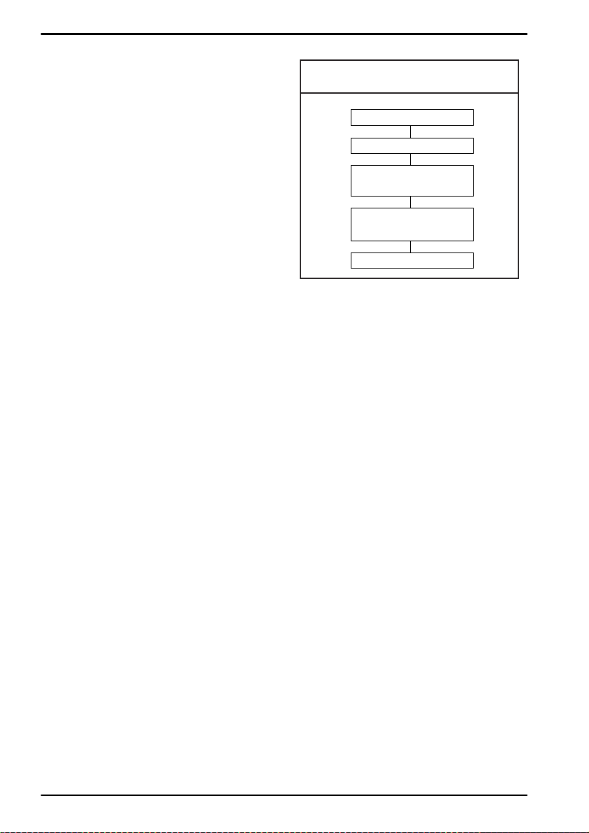
See figure 3.06.
Fig. 3.06. Setting Fixed length ON
all codes
SET
Fixed length ON
Scan a bar code
with the required length
Scan a 2nd bar code
with the required length
END
It is possible to configure a fixed length or a
minimum and a maximum length for selected
symbologies by reading the respective option
followed by a barcode label with the required
length. The different functions may be
combined and will be used as follows:
• if a label is checked for fixed length, it will not
be checked for minimum or maximum length
• if a label is not checked for fixed length it will
be checked for both minimum and maximum
length
By reading an option followed by the 'END'
label, the function is disabled or the values for
that option are reset to their default. The default
values are:
• fixed: disabled, thus no fixed length checking
• minimum: according to the next figure (The
minimum length of the 2of5 bar code types
can not be changed independent.)
• maximum: disab led, thus no maximum length
checking. (The maximum length is reader
dependent)
See figure 3.07.
U42
Page 49
OPTICON UNIVERSAL MENU BOOK
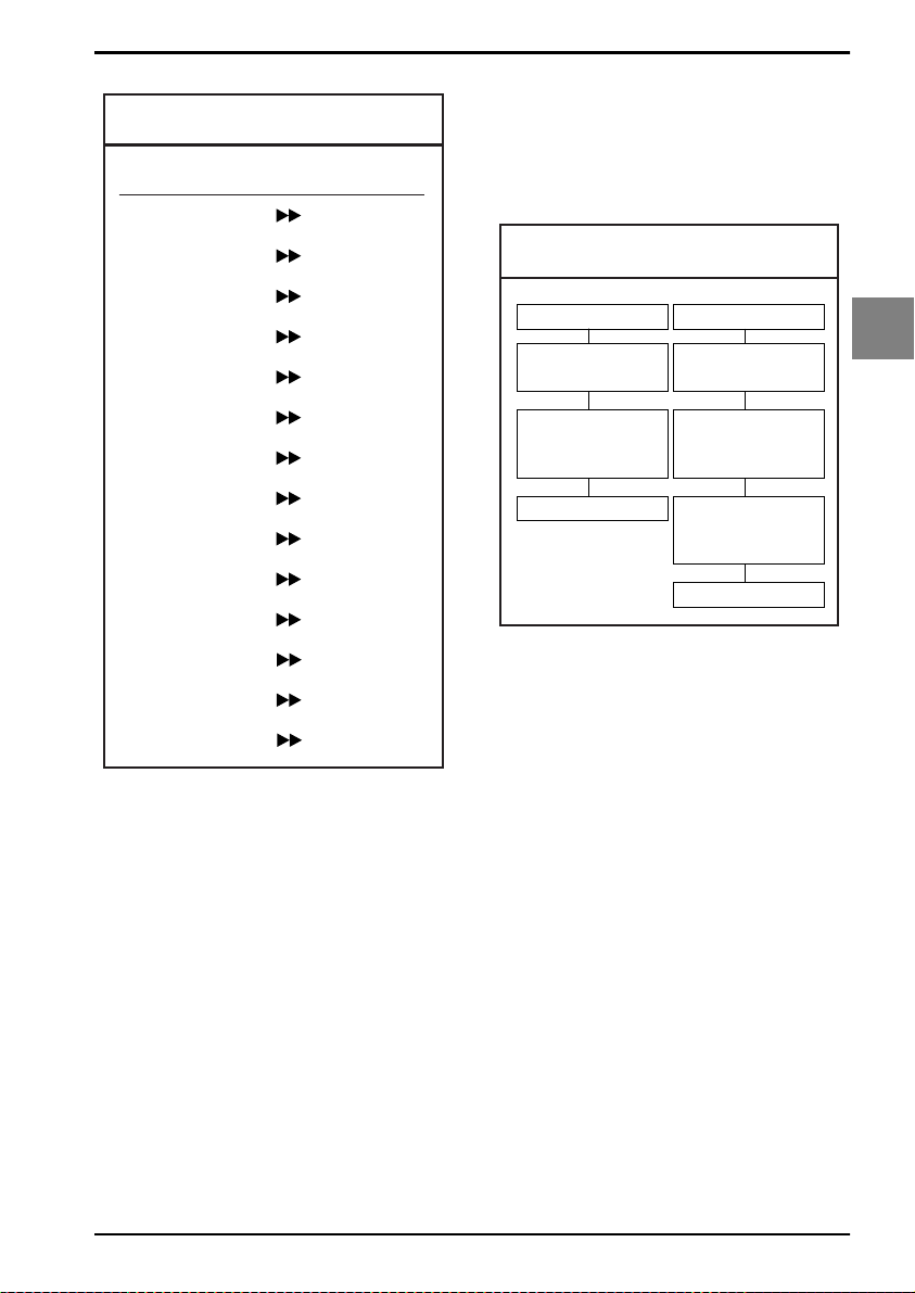
Fig. 3.07. Setting Minimum length table
Code type:
Minimum length
characters and Interleaved 2of5 labels for a
length of 12 characters. This implies that also
Industrial 2of5, Matrix 2of5 and S-Code are
checked for a fix ed length of 12 characters . Any
other bar code type will not be checked for fix ed
length. See figure 3.08.
Codabar
Code 11
Code 39
Code 93
Code 128
Industrial 2of5
Interleaved 2of5
IATA
Matrix 2of5
MSI/Plessey
UK/Plessey
RSS-expanded
S-Code
Telepen
5
1
1
1
1
5
6
5
5
3
2
1
5
1
Fixed length ON for selected codes:
This option enables fixed length checking for
different bar code types and will only affects the
bar code types read. The number of fixed
lengths which can be configured is reader
dependent.
<SET>
<Fixed length ON for selected codes>
Scan bar codes of the required type and length
<END>
Example:
The 2 examples shown in the next figure have
the following results: In the first example only
Code 39 labels will be checked for a length of 6
characters. Any other bar code type will not be
checked for fix ed length. In the second example
Code 39 labels will be checked for a length of 6
Fig. 3.08. Setting Fixed length ON
selected codes
SET
Fixed length ON
for selected only
Scan a label,
i.e. Code 39
with length = 6
END
SET
Fixed length ON
for selected only
Scan a label,
i.e. Code 39
with length = 6
Scan a label,
i.e. Interleaved 2of5
with length = 12
END
Minimum length for selected codes:
This option modifies the default minimum
length table. The number of minimum lengths
which can be configured is reader dependent.
This is done by reading the following labels:
<SET>
<Minimum length for selected codes>
Scan bar codes of the required type and length
<END>
Example:
The two examples shown in the next figure
have the following result: In the first example
only Code 39 labels will be checked for a
minimum length of 2 characters. All other bar
code types will be checked for a minimum
length as displayed in the next figure.
In the second example Code 39 labels will be
checked for a minimum length of 2 characters
and Interleaved 2of5 labels for a minimum
length of 4 characters. This implies that also
Industrial 2of5, Matrix 2of5 and S-Code are
checked for a minimum length of 4 characters.
All other bar code types will be checked for a
minimum length as per figure 3.09.
3
Code options
U43
Page 50
OPTICON UNIVERSAL MENU BOOK
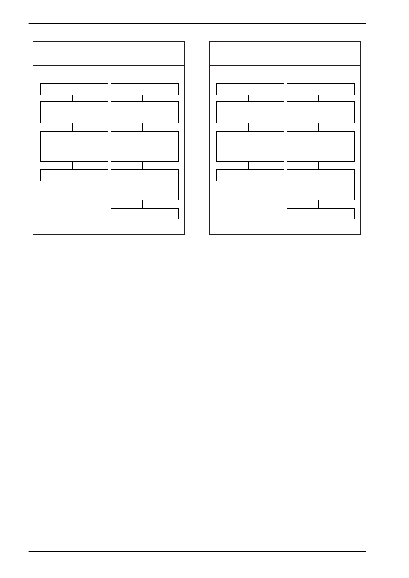
Fig. 3.09. Setting Minimum length
for selected codes
SET
Minimum length
for selected codes
Scan a label,
i.e. Code 39
with length = 2
END
SET
Minimum length
for selected codes
Scan a label,
i.e. Code 39
with length = 2
Scan a label,
i.e. Interleaved 2of5
with length = 4
END
Maximum length for selected codes:
This option enables the maximum length
checking. The number of maximum lengths
which can be configured is reader dependent.
This is done by reading the following labels:
<SET>
<Maximum length for selected codes>
Scan bar codes of the required type and length
<END>
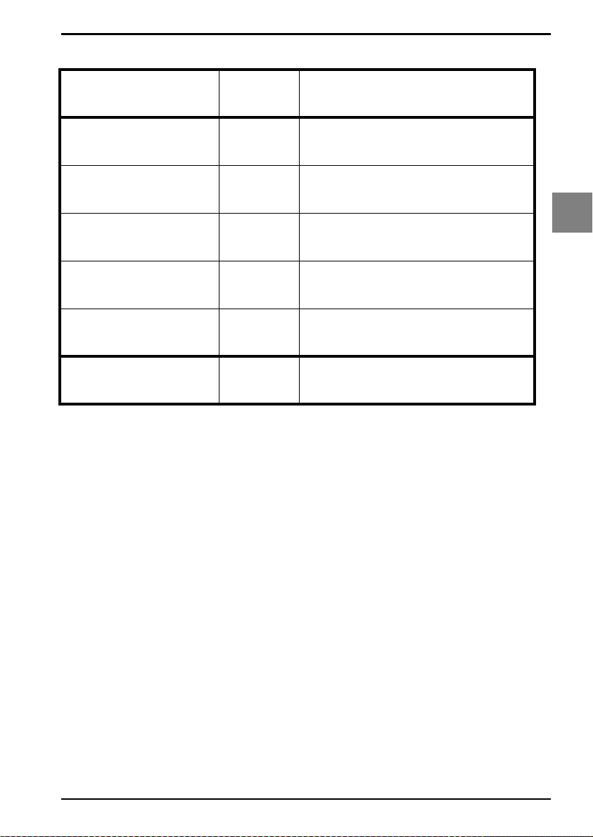
Fig. 3.10. Setting Maximum length
for selected codes
SET
Maximum length
for selected codes
Scan a label,
i.e. Code 39
with length = 12
END
SET
Maximum length
for selected codes
Scan a label,
i.e. Code 39
with length = 12
Scan a label,
i.e. Interleaved 2of5
with length = 14
END
Example:
The two following examples shown in the next
figure have the following result: In the first
example only Code 39 labels will be checked
for a maximum length of 12 characters. Any
other bar code types will not be checked for a
maximum length. In the second example Code
39 labels will be checked for a maximum length
of 12 characters and Interleaved 2of5 labels for
a maximum length of 14 characters. This
implies that also Industrial 2of5, Matrix 2of5
and S-Code are checked for a maximum length
of 14 characters. Any other bar code types will
not be checked for a maximum length. See
figure 3.10.
U44
Page 51
OPTICON UNIVERSAL MENU BOOK
3.2. Setting of number of characters
Fixed length OFF all
codes
Fixed length ON all
codes
Fixed length ON for
selected codes
Minimum length for
selected codes
Maximum length for
selected codes
SET
H0
H1
HK
HL
HM
END
_ZZ_
_H0_
_H1_
_HK_
_HL_
_HM_
_ZZ_
3
Code options
U45
Page 52

OPTICON UNIVERSAL MENU BOOK
3.3. Setting code specific options
Code specific options may be configured
affecting:
• enabling and disabling code variants and
translations, such as EAN-128, as were listed
in the relations table for setting of readable
codes
• data v erification such as by means of a check
digit calculation. A check digit has a value
that can be calculated from the other data
characters and is usually the last data
character in a bar code
• pre-editing of the data string such as
removing the check-digit and/or start/stop
characters
The more common options are described here:
Check CD:
This option enables the check digit calculation.
If the calculated check digit does not
correspond to the check digit in the bar code,
then the bar code is ignored. The use of a
check digit greatly improves the security of a
bar code.
Not check CD:
This option disables the check digit calculation.
This option is required when the bar codes do
not contain a check digit or contain an invalid
check digit.
Transmit CD:
This option enables the transmission of the
check digit together with the data characters.
If the check digit calculation is disabled, the
reader can not differentiate anymore between a
(valid) check digit and a data character. It will
therefore transmit all data characters of the
label, including what could constitute a check
digit.
Not transmit CD:
This option disables the transmission of the
check digit. If the check digit calculation is
disabled, the reader can not differentiate
between a (valid) check digit and a data
character. It will therefore transmit all data
characters of the label, excluding the character
that could constitute the check digit for the type
of bar code.
Transmit ST/SP:
This option enables the transmission of the
start and stop characters of a bar code.
Not transmit ST/SP:
This option disables the transmission of the
start and stop characters of a bar code. The
next figure summarizes the effect of the
transmit options for a Code 39 label with:
• start and stop characters '*'
• data characters '1 2 3 4 5 6'
• or data characters '1 2 3 4 5' and check digit
'6'
Note that because '6' is, according to the Code
39 specifications, not a valid check digit for this
label. The check digit calculation must therefore
be disabled in order for the label to be
accepted.
See figure 3.11.
Fig. 3.11. Setting code specific options
Transmit ST/SP
Not transmit ST/SP
Transmit CD
* 1 2 3 4 5 6 *
1 2 3 4 5 6
Not transmit CD
* 1 2 3 4 5 *
1 2 3 4 5
U46
Page 53
3.3.1. Options for UPC-A
OPTICON UNIVERSAL MENU BOOK
The UPC-A symbology is a fixed length
symbology encoding 11 data digits, a check
digit and non printable start/stop characters.
The following characters are supported:
• the digits 0 up to 9
An optional leading zero can be transmitted,
which together with the data and the check digit
forms a 13 digit field providing compatibility with
the EAN-13 format. For string format see figure
3.12.
UPC-A add-on 2/add-on 5:
The UPC-A symbology as described above can
be succeeded by an additional 2 or 5 digit UPCA code. For string format see figure 3.13.
Options for UPC-A:
• disable transmission of the leading zero
• disable transmission of the check digit
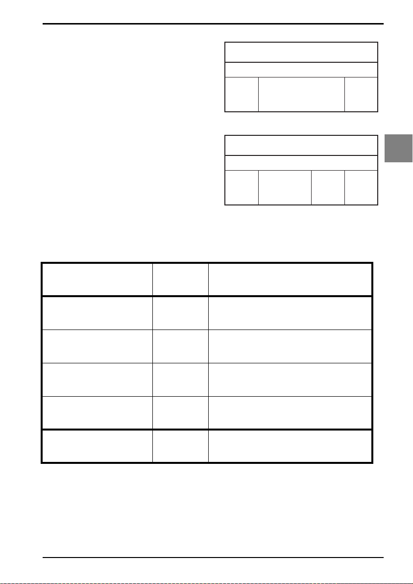
SET
UPC-A, No leading
zero, transmit CD
E3
Fig. 3.12. Options for UPC-A
UPC-A
leading
zero
Fig. 3.13. Options for UPC-A
leading
zero
(11 digits)
UPC-A +2, +5
data
(11 digits)
data
check
digit
check
digit
3
Code options
add-on
2 or 5
_ZZ_
_E3_
UPC-A, No leading zero,
not transmit CD
UPC-A, Leading zero,
transmit CD
UPC-A, Leading zero, not
transmit CD
E5
E2
E4
END
_E5_
_E2_
_E4_
_ZZ_
U47
Page 54
3.3.2. Options for UPC-E
OPTICON UNIVERSAL MENU BOOK
The UPC-E symbology is a fixed length
symbology encoding 6 data digits, a check digit
and non printable start/stop characters. The
following characters are supported:
• the digits 0 upto 9
An optional leading digit can be transmitted,
which together with the data and the check digit
forms an 8 digit field providing a compatibility
with the EAN-8 format. For string format see
figure 3.14.
UPC-E add-on 2/add-on 5:
The UPC-E symbology as described above can
be succeeded by an additional 2 or 5 digit UPCE code. For string format see figure 3.15.
UPC-E0 stands for UPC version E0 and the
first digit is always a '0'. UPC-E1 sta nd f or UPC
version E1 and the first digit is a '1'. Options for
UPC-E0 affects UPC-E1 too. Support for UPCE1 is reader dependent.
Options for UPC-E:
• enable transmission of the leading digit
• disable transmission of the check digit
• transmit UPC-E as UPC-A
Transmit UPC-E as UPC-A:
If this option is enabled, a UPC-E label is
transmitted in the UPC-A format.
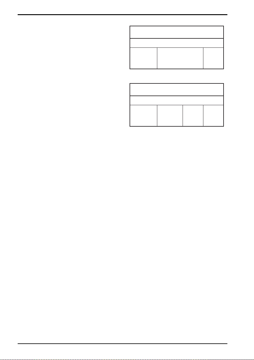
Fig. 3.14. Options for UPC-E
UPC-E
leading digit
(0 or 1)
data
(6 digits)
Fig. 3.15. Options for UPC-E
UPC-E +2, +5
leading digit
(0 or 1)
data
(6 digits)
check
digit
check
digit
add-on
2 or 5
U48
Page 55
3.3.2. Options for UPC-E
OPTICON UNIVERSAL MENU BOOK
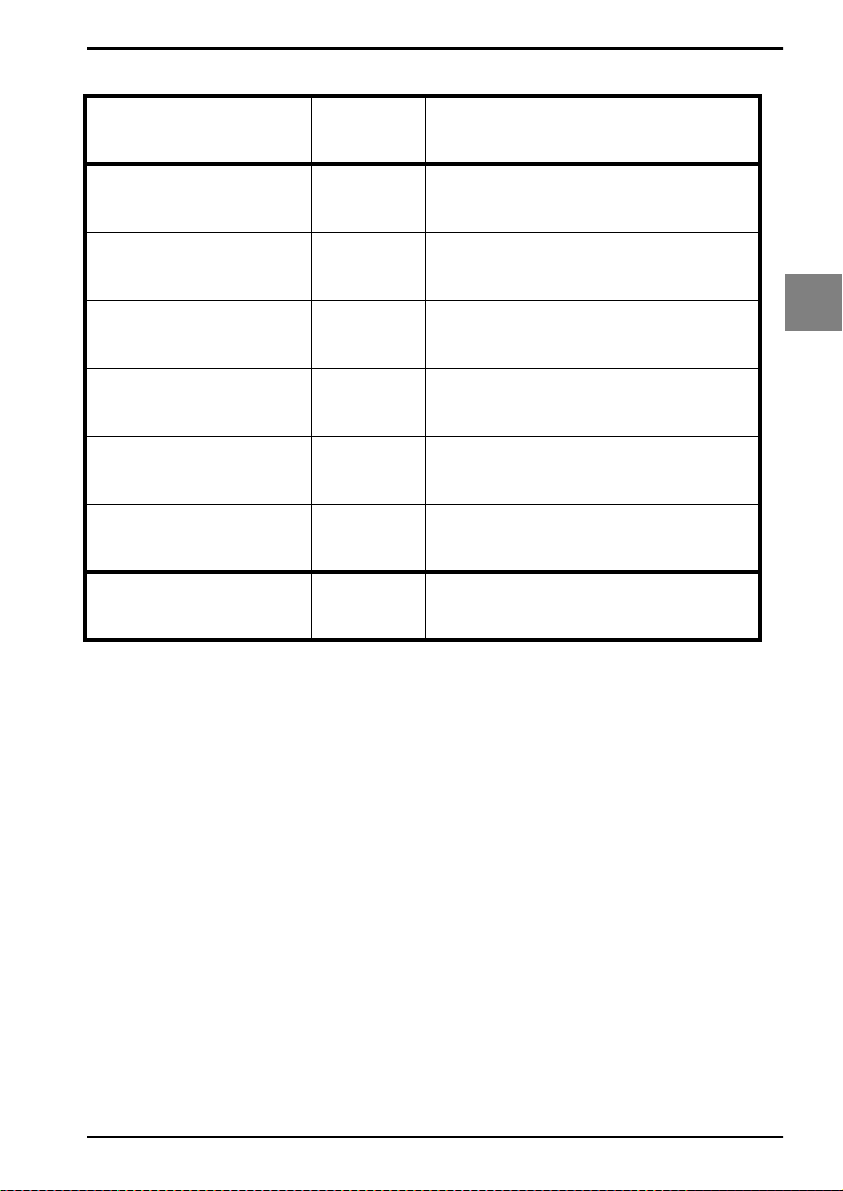
UPC-E, No leading
digit, transmit CD
UPC-E, No leading digit,
not transmit CD
UPC-E, Leading digit,
transmit CD
UPC-E, Leading digit, not
transmit CD
Transmit UPC-E as is
Transmit UPC-E as UPCA
SET
E7
E9
E6
E8
6Q
6P
END
_ZZ_
_E7_
_E9_
_E6_
_E8_
_6Q_
_6P_
_ZZ_
3
Code options
U49
Page 56
OPTICON UNIVERSAL MENU BOOK
3.3.3. Options for EAN-13 and EAN-8
EAN-13:
The EAN-13 symbology is a fixed length
symbology encoding 12 data digits, a check
digit and non printable start/stop characters.
The following characters are supported:
• the digits 0 upto 9
The data may be translated into ISBN, ISSN or
ISMN format. For string format see figure 3.16.
EAN-13 add-on 2/add-on 5:
The EAN-13 symbology as described above
can be succeeded by an additional 2 or 5 digit
code. For string format see figure 3.17.
EAN-8:
The EAN-8 symbology is a fixed length
symbology encoding 7 data digits, a check digit
and non printable start/stop characters.
The following characters are supported:
• the digits 0 upto 9
For string format see figure 3.18.
EAN-8 add-on 2/add-on 5:
The EAN-8 symbology as described above can
be succeeded by an additional 2 or 5 digit code.
For string format see figure 3.19.
Options for EAN:
• disable transmission of the check digit
• enable ISBN, ISSN or ISMN translation
Enable ISBN, ISSN or ISMN translation:
If this option is enabled, an EAN-13 label is
verified for the correct format and transmitted
as a 10-digit ISBN number, 8 digit ISSN
number. In case of ISMN, the character M is
transmitted followed by 9 digits. Support for
these translations is reader dependent.
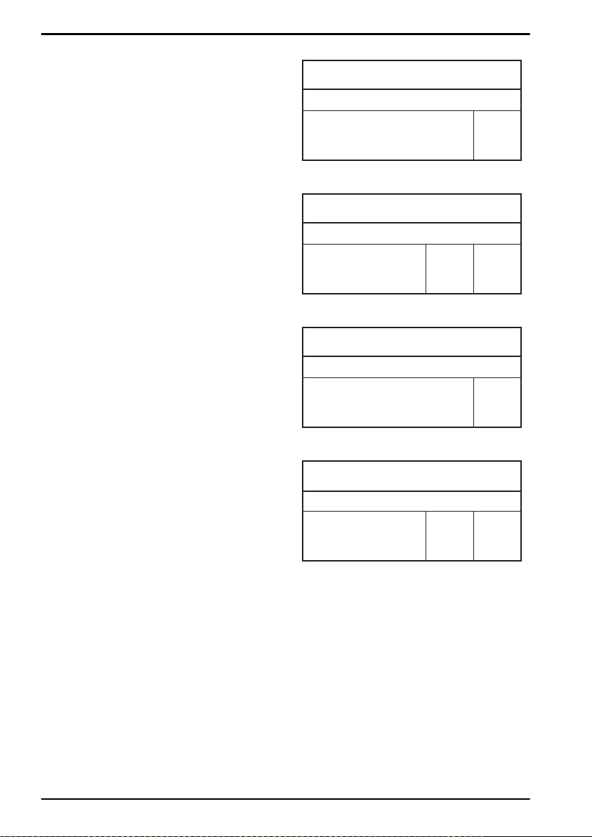
Fig. 3.16. Options for EAN-13 and EAN-8
EAN-13
data
(12 digits)
check
digit
Fig. 3.17. Options for EAN-13 and EAN-8
EAN-13, +2,+5
data
(12 digits)
check
digit
add-on
2 or 5
Fig. 3.18. Options for EAN-13 and EAN-8
EAN-8
data
(7 digits)
check
digit
Fig. 3.19. Options for EAN-13 and EAN-8
EAN-8, +2,+5
data
(7 digits)
check
digit
add-on
2 or 5
U50
Page 57
OPTICON UNIVERSAL MENU BOOK
3.3.3. Options for EAN-13 and EAN-8
EAN-13 not transmit CD
EAN-13 transmit CD
EAN-8 not transmit CD
EAN-8 transmit CD
Disable ISBN
translation
Enable ISBN translation
Enable ISBN if possible
Disable ISSN
translation
SET
6J
6K
6H
6I
IB
IA
IK
HN
_ZZ_
_6J_
_6K_
_6H_
_6I_
_IB_
_IA_
_IK_
_HN_
3
Code options
Enable ISSN translation
Enable ISSN if possible
Disable ISMN
translation
Enable ISMN translation
Enable ISMN if possible
HO
4V
IO
IP
IQ
END
_HO_
_4V_
_IO_
_IP_
_IQ_
_ZZ_
U51
Page 58
OPTICON UNIVERSAL MENU BOOK
3.3.4. Options for Code 39 and It. Pharm.
Code 39:
Code 39 is a variable length symbology with an
optional check digit and printable start/stop
characters. The following characters are
supported:
• the digits 0 up to 9
• the upper case characters A up to Z
• the characters - . $ / + % SPACE
• start/stop character is *
The checksum is calculated as the sum modulo
43 of the numerical value of the data
characters. In full ASCII mode, all 128 ASCII
characters are supported. This is done by
combining one of the characters +, %, $ or /
with one of the alpha characters (A upto Z). For
string format see figure 3.20.
Italian Pharmaceutical:
In this mode the Code 39 data is translated to
the Italian pharmaceutical format. This format
has a fixed length containing 8 numeric data
values followed by a single mandatory check
digit. An optional leading 'A' can be transmitted.
For string format see figure 3.21.
Italian Pharmaceutical only:
In this mode the decoded data characters are
translated to the Italian Pharmaceutical format.
If the data does not comply with the Italian
Pharmaceutical format, the label is rejected.
Italian Pharmaceutical if possible:
In this mode the decoded data characters are
translated to the Italian Pharmaceutical format.
If the data does not comply with the Italian
Pharmaceutical format, then the data is
transmitted as Normal or full ASCII Code 39.
Concatenation:
If a Code 39 bar code contains a leading space,
the data is stored into the reader's buffer
without the leading space. As soon as a Code
39 bar code is read without a leading space,
the data is appended to the reader's buffer and
the entire buffer is transmitted and cleared for
new data. In case a non Code 39 bar code is
read, the data in the non-Code 39 bar code is
transmitted and the buffer is cleared. The b uff er
size is reader dependent.
Options for Code 39:
• enable full ASCII conversion
• enable Italian Pharmaceutical conversion
• enable check digit
• disable transmission of the check digit
• enable transmission of start/stop
• enable leading A for Italian Pharmaceutical
• selection of the minimum number of data
characters
Normal Code 39:
In this mode the decoded data characters are
transmitted without further translation.
Full ASCII Code 39:
In this mode the decoded data characters are
translated to full ASCII Code 39.
Full ASCII Code 39 if possible:
In this mode the decoded data characters are
translated to full ASCII Code 39. Invalid
combinations are not translated and are
transmitted as is.
Fig. 3.20. Options for Code 39 and It.Pharm.
Code 39
start
char.
data
(0 or more char.)
check
digit
Fig. 3.21. Options for Code 39 and It.Pharm.
Italian Pharmaceutical
data
(8 digits)
U52
start
char.
leading
A
check
digit
stop
char.
stop
char.
Page 59
OPTICON UNIVERSAL MENU BOOK
3.3.4. Options for Code 39 and It.Pharm.
Normal Code 39
Full ASCII Code 39
Full ASCII Code 39 if
possible
It. Pharmaceutical only
It. Pharmaceutical if
possible
Not check CD
Check CD
Not transmit CD
SET
D5
D4
+K
D6
D7
C1
C0
D8
_ZZ_
_D5_
_D4_
_+K_
_D6_
_D7_
_C1_
_C0_
_D8_
3
Code options
Tr ansmit CD
Not transmit ST/SP
Transmit ST/SP
Not transm. ld. A for It.
Pharm.Code
Transmit leading A for It.
Pharm.Code
D9
D1
D0
DA
DB
END
_D9_
_D1_
_D0_
_DA_
_DB_
_ZZ_
U53
Page 60

OPTICON UNIVERSAL MENU BOOK
Minimum 3 digits
Minimum 1 digit
Disable concatenation
Enable concatenation
SET
8D
8E
+M
+L
END
_ZZ_
_8D_
_8E_
_+M_
_+L_
_ZZ_
U54
Page 61
3.3.5. Options for Codabar
OPTICON UNIVERSAL MENU BOOK
Codabar (NW7):
Codabar (NW7) is a variable length symbology
with an optional check digit and printable start/
stop characters. The next characters are
supported:
• the digits 0 upto 9
• the characters - $: / . +
• start/stop characters are A, B, C or D
The checksum is calculated as the sum modulo
16 of the numerical values of all data
characters. For string format see figure 3.22.
ABC-Code:
The ABC code is an acronym for American
Blood Commission. This code consists of two
bar codes which are decoded in one read
cycle. The code is concatenated when the stop
character of the first bar code and the start
character of the second bar code is a D. These
two D's are not transmitted. For string format
see figure 3.23.
CX-Code:
The CX-Code consists of two bar codes which
are decoded in one read cycle. The code is
concatenated when the stop character of the
first bar code is a C, and the start character of
the second bar code is a B. The B and C
characters are not transmitted. For string
format see figure 3.24.
Fig. 3.23. Options for Codabar
ABC Code
start
char.
data (1 or
more char.)
check
digit
Fig. 3.24. Options for Codabar
CX Code
start
char.
data (1 or
more char.)
check
digit
data (1 or
more char.)
data (1 or
more char.)
check
digit
check
digit
stop
char.
3
Code options
stop
char.
Options for Codabar:
• enable ABC code concatenation
• enable CX code concatenation
• enable check digit check
• disable transmission of the check digit
• disable transmission of start/stop
• selection of start/stop character translation
• selection of minimum number of data
characters
• enable library space (CLSI) insertion
Fig. 3.22. Options for Codabar
Codabar
start
char.
data
(1 or more char.)
check
digit
stop
char.
U55
Page 62
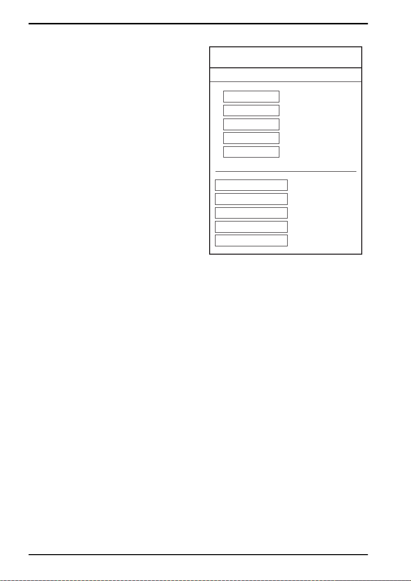
OPTICON UNIVERSAL MENU BOOK
Space insertion:
This option inserts spaces in position 2, 7, 13,
of the data string for use in library systems.
ST/SP translation:
This option enables the translation and
transmission of the start and stop characters.
Thus if the option ST/SP: abcd/tn*e is chosen,
the start character is converted to lower case,
e.g. from A, B, C or D to a, b, c, or d
respectively and the stop character is
converted from A, B, C or D to t, n, *, or e
respectively. The next figure shows the
resulting format for these options with a
Codabar label using A and B as start and stop
characters and 1 2 3 4 5 6 as data characters.
For string format see figure 3.25.
Minimum data characters:
Codabar labels are checked for a minimum of
1, 3 or 5 characters are set by the user. If the
number of characters in the label is shorter
than the number set, the label will be rejected.
If the fixed length option is used for Codabar
type labels then such labels will additionally be
checked for fixed length.
Inter character gap check:
This option enables the reading of Codabar
labels with a large or irregular gap between
characters. Checking the gap means that it is
not allowed to have a gap. Disable the gap
check allows gaps in the bar code.
Fig. 3.25. Options for Codabar
Codabar Start and Stop
1 2 3 4 5 6
A 1 2 3 4 5 6 B
a 1 2 3 4 5 6 b
A 1 2 3 4 5 6 N
a 1 2 3 4 5 6 n
<DC1> 1 2 3 4 5 6 <DC2>
<DC1>
<DC2>
<DC3>
<DC4>
Not transmit ST/SP
ST/SP: ABCD/ABCD
ST/SP: abcd/abcd
ST/SP: ABCD/TN*E
ST/SP: abcd/tn*e
ST/SP: ASCII Hex 11
ST/SP: ASCII Hex 12
ST/SP: ASCII Hex 13
ST/SP: ASCII Hex 14
U56
Page 63
3.3.5. Options for Codabar
OPTICON UNIVERSAL MENU BOOK
Enable only Codabar
normal mode
Enable only ABC code
Enable only CX code
Enable Codabar, ABC
and CX
Not check CD
Check CD
Not transmit CD
Tr ansmit CD
SET
HA
H4
H5
H3
H7
H6
H9
H8
_ZZ_
_HA_
_H4_
_H5_
_H3_
_H7_
_H6_
_H9_
_H8_
3
Code options
Disable space insertion
Enable space insertion
Not transmit ST/SP
ST/SP: ABCD/ABCD
ST/SP: abcd/abcd
HE
HD
F0
F3
F4
END
_HE_
_HD_
_F0_
_F3_
_F4_
_ZZ_
U57
Page 64

OPTICON UNIVERSAL MENU BOOK
ST/SP: ABCD/TN*E
ST/SP: abcd/tn*e
ST/SP:
<DC1><DC2><DC3><DC4>/
<DC1><DC2><DC3><DC4>
Minimum data one
character
Minimum data three
characters
Minimum data five
characters
Disable intercharact er
gap check
Enable intercharacter
gap check
SET
F1
F2
HJ
HC
HB
HF
HI
HH
_ZZ_
_F1_
_F2_
_HJ_
_HC_
_HB_
_HF_
_HI_
_HH_
END
_ZZ_
U58
Page 65
OPTICON UNIVERSAL MENU BOOK
3.3.6. Options for 2of5 and S-Code
Code 2of5:
Code 2of5 is a variable length symbology with
an optional check digit and non printable start
and stop characters. The following characters
are supported:
• the digits 0 upto 9
The checksum is calculated as the sum modulo
10 of the numerical values of all the data
characters.
Industrial 2of5:
This symbology encodes a single digit in each
data symbol. Information is carried in the bars
only.
Interleaved 2of5:
This symbology encodes a pair of digits in each
symbol, the number of digits are therefore
always an even number. Information is carried
in the bars and spaces. The start and stop
pattern is not unique inside the code. It is
therefore essential to use the fixed length
option to prevent partial reads.
Options for code 2of5:
• disable transmission of the check digit
• enable check digit check
• selection of the minimum number of data
characters
• disable space check for industrial 2of5
• transmit S-Code as Interleaved 2of5
Minimum data characters:
Code 2of5 are checked for a minimum of 1, 3 or
5 characters as set by the user. If the n umber of
characters in the label is less then the number
set, the label will be rejected. If the fixed length
option is used for a Code 2of5 type label, than
such label will additionally be checked for fixed
length.
Space check:
This option enables the reading of Industrial
2of5 labels with a large or irregular spacing.
Transmit S-Code as Interleaved 2of5:
This option enables to transmit S-Code as
Interleaved 2of5 by adding a leading zero.
3
Code options
S-Code:
This symbology encodes like Interleaved 2of5
but encodes the last data character as
Industrial 2of5. The number of data digits is
therefore always an odd number.
Information is carried in the bars and the
spaces.The start and stop pattern is not unique
inside the code. It is therefore essential to use
the fixed length option to prevent partial reads.
Matrix 2of5:
This symbology encodes 1 digit in each
character, the number of digits can therefore be
an odd or an even number. Information is
carried in the bars and spaces.
For string format of the supported symbologies
see figure 3.26.
Fig. 3.26. Options for 2of5 and S-Code
Industrial 2of5, Interleaved 2of5, S-Code, Matrix 2of5
leading
zero
(optional)
U59
data
(1 or more digits)
check
digit
Page 66

OPTICON UNIVERSAL MENU BOOK
3.3.6. Options for 2of5 and S-Code
Not transmit CD
T ransmit CD
Not check CD
Check CD
Minimum data one
character
Minimum data three
character
Minimum data five
character
Disable space check for
Industrial 2of5
SET
E1
E0
G0
G1
GE
GF
GI
GK
_ZZ_
_E1_
_E0_
_G0_
_G1_
_GE_
_GF_
_GI_
_GK_
Enable space check for
Industrial 2of5
Not transmit S-Code as
Interleaved 2of5
Transmit S-Code as
Interleaved 2of5
GJ
GH
GG
END
_GJ_
_GH_
_GG_
_ZZ_
U60
Page 67
OPTICON UNIVERSAL MENU BOOK
3.3.7. Options for IATA
The IATA code is a variable length symbology
with an optional check digit and non printable
start/stop characters. The following characters
are supported:
• the digits 0 upto 9
The checksum is calculated as the modulo
seven of the data string. IATA is acronym for
International Air Transport Association. For
string format see figure 3.27.
Options for IATA:
• enable check digit check
• selection of the check digit calculation
• disable transmission of the check digit
Check digit calculation:
If the check digit calculation is required, then
the appropriate calculation method must be
selected.
Fig. 3.27. Options for IATA
IATA
CD
check
digit
(1 digit)
CPN
coupon
(1digit)
AC
airline
code
(3 digits)
FC
form
code
(2 digits)
SN
serial
number
(8 digits)
3
Code options
Not check CD
Check FC and SN only
Check CPN, FC and SN
Check CPN, AC, FC and
SN
Not transmit CD
Tr ansmit CD
SET
4H
4I
4J
4K
4M
4L
END
_ZZ_
_4H_
_4I_
_4J_
_4K_
_4M_
_4L_
_ZZ_
U61
Page 68

OPTICON UNIVERSAL MENU BOOK
3.3.8. Options for MSI/Plessey
MSI Plessey is a variable length symbology
with one or two optional check digit calculations
CD1 and CD2 and non printable start/stop
characters. The following characters are
supported:
• the digits 0 up to 9
The checksum is calculated as the sum modulo
10 or 11 of the data characters. The checksum
CD2 is calculated as the sum modulo 10 or 11
of the data characters and CD1. For string
format see figure 3.28.
Options for MSI/Plessey:
• disable check digit check
• selection of the check digit calculation
• selection of the number of check digits to be
transmitted
Check digit:
If the check digit calculation is required, then
the appropriate calculation method must be
selected.
Not transmit CD:
The character positions CD1 and CD2 are not
transmitted.
Transmit CD1:
The character position CD2 is not transmitted.
Transmit CD1 and CD2:
All characters in the label are transmitted.
Fig. 3.28. Options for MSI/Plessey
MSI/Plessey
data
(1 upto 13 digits)
cd1 cd2
U62
Page 69
3.3.8. Options for MSI/Plessey
OPTICON UNIVERSAL MENU BOOK
Not check CD
Check 1 CD = MOD 10
Check 2 CD's = MOD 10/
MOD 10
Check 2 CD's = MOD 10/
MOD 11
Check 2 CD's = MOD 11/
MOD 10
Not transmit CD
Transmit CD1
Transmit CD1 and CD2
SET
4A
4B
4C
4D
4R
4G
4E
4F
_ZZ_
_4A_
_4B_
_4C_
_4D_
_4R_
_4G_
_4E_
_4F_
3
Code options
END
_ZZ_
U63
Page 70
3.3.9. Options for Telepen
OPTICON UNIVERSAL MENU BOOK
Telepen is a variable length symbology with a
check digit and non printable start/stop
characters. The following characters are
supported:
• in numeric mode, the digits 00 upto 99
• in full ASCII mode, all 128 ASCII characters
The check digit calculation is derived from the
sum of all data characters modulo 127. The
check digit cannot be transmitted. For string
format see figure 3.29.
Options for Telepen:
• selection of ASCII mode
SET
Numeric mode
ASCII mode
D2
D3
END
Fig. 3.29. Options for Telepen
Telepen
data
(1 upto 32 characters)
check
digit
_ZZ_
_D2_
_D3_
_ZZ_
U64
Page 71
OPTICON UNIVERSAL MENU BOOK
3.3.10. Options for UK/Plessey
UK Plessey is a variable length symbology with
a mandatory checksum and non printable start/
stop characters. The following characters are
supported:
• the digits 0 upto 9
• the characters A upto F
The checksum contains 2 digits and is
calculated from the numerical values of all the
data digits. For string format see figure 3.30.
Options for UK Plessey:
• enable A to X conversion
• disable transmission of the check digits
• enable library space (CLSI) insertion
Space insertion:
This option inserts spaces in position 2, 5, 11,
14 of the data string for use in library systems.
A to X conversion:
This option converts the character 'A' into an
'X'. The data and check digits are affected.
Fig. 3.30. Options for UK/Plessey
UK/Plessey
data
(5 upto 20 characters)
check
digits
3
Code options
Not transmit CD's
Transmit CD's
Disable space insertion
Enable space insertion
Disable A to X
conversion
Enable A to X conversion
SET
4O
4N
DO
DN
DP
DQ
END
_ZZ_
_4O_
_4N_
_DO_
_DN_
_DP_
_DQ_
_ZZ_
U65
Page 72
OPTICON UNIVERSAL MENU BOOK
3.3.11. Options for Code 128 and EAN-128
Code 128:
Code 128 is a variable length symbology with a
mandatory check digit and non printable start/
stop characters. The following characters are
supported:
• all 128 ASCII characters
• 4 non data function characters
• 3 start characters
• 4 code set selection characters
• 1 stop character
The check digit is calculated as the sum
modulo 103 of the start character and the
weighted values of the data and special
characters. For string format see figure 3.31.
Options for Code 128:
• enable concatenation
EAN-128:
In this mode the Code128 data is translated to
the EAN-128 format. EAN-128 data starts with
the FNC1 character and separates 2 data fields
with the FNC1 character.
The first FNC1 character is translated to ]C1,
and the second FNC1 character is translated to
an ASCII GS (hex 1D) character. For string
format see figure 3.32.
new data. In case a non Code 128 bar code is
read, the data in the non-Code 128 bar code is
transmitted and the buffer is cleared. The b uff er
size is reader dependent.
Fig. 3.31. Options for Code 128 and EAN-128
Code 128
data
(1 or more characters)
Fig. 3.32. Options for Code 128 and EAN-128
EAN-128
]C1 data
(1 or more char.)
<GS>
data
(1 or more char.)
Options for EAN-128:
• enable EAN128 conversion
Enable EAN-128 only:
In this mode the decoded data characters are
translated to the EAN-128 format. If the data
does not comply with the EAN-128 format, then
the label is rejected.
Enable EAN-128 if possible:
In this mode the decoded data characters are
translated to the EAN-128 format. If the data
does not comply with the EAN-128 format, then
the label is transmitted as code 128.
FNC2 Concatenation:
If a Code 128 bar code contains a leading
FNC2 character, the data is stored into the
reader's buffer. As soon as a Code 128 bar
code is read without a leading FNC2 character,
the data is appended to the reader's buffer and
the entire buffer is transmitted and cleared for
U66
Page 73
OPTICON UNIVERSAL MENU BOOK
3.3.11. Options for Code 128 and EAN-128
Disable EAN-128
Enable EAN-128 only
Enable EAN-128 if
possible
Disable concatenation
Enable concatenation
SET
OF
JF
OG
MP
MO
END
_ZZ_
_OF_
_JF_
_OG_
_MP_
_MO_
_ZZ_
3
Code options
U67
Page 74

3.3.12. Options for Code 93
OPTICON UNIVERSAL MENU BOOK
Code 93 is a variable length symbology with 2
mandatory check digits and non printable start/
stop characters. The following characters are
supported:
• the digits 0 upto 9
• the upper case characters A upto Z
• the characters - . $ / + % SPACE
• 4 non printable shift characters
The first check digit (C) is the modulo 47 sum of
the weighted data character values. The
second check digit (K) is the modulo 47 sum of
the weighted data character values including
the first check digit (C). The check digits are not
transmitted.
The special shift characters are control
characters and are not transmitted with the
data. If one of these characters is followed by
an upper case character 'A' upto 'Z', it is
transmitted as 1 single character. In case of an
invalid combination, the label is rejected. This
method enables support for full 128 ASCII
characters encodation. The encodation is
compatible with the Code 39 $, %, / and +
characters. For string format see figure 3.33.
Options for Code 93:
• enable concatenation
• transmission of check digits
• calculation of check digits
Fig. 3.33. Options for Code 93
Code 93
data
(1 or more characters)
check
digit
C
check
digit
K
Concatenation:
If a Code 93 bar code contains a leading space,
the data is stored into the reader's buffer
without the leading space. As soon as a Code
93 bar code is read without a leading space,
the data is appended to the reader's buffer and
the entire buffer is transmitted and cleared for
new data. In case a non Code 93 bar code is
read, the data in the non-Code 93 bar code is
transmitted and the buffer is cleared. The buff er
size is reader dependent. Support for this
option is reader dependent.
U68
Page 75
3.3.12. Options for Code 93
OPTICON UNIVERSAL MENU BOOK
Not check CD
Check CD
Not transmit CD
Transmit CD
Disable concatenation
Enable concatenation
SET
9Q
AC
DZ
DY
+W
+V
END
_ZZ_
_9Q_
_AC_
_DZ_
_DY_
_+W_
_+V_
_ZZ_
3
Code options
U69
Page 76

OPTICON UNIVERSAL MENU BOOK
3.3.13. Options for Code 11
Code 11 is a variable length symbology with 1
or 2 optional check digits and non printable
start/stop characters. If the data is 10 or less
characters, one check digit is used. If the data
is more then 10 characters, then 2 check digits
are used. The following characters are
supported:
• the digits 0 upto 9
• the dash character '-'
Options for Code 11:
• disable check digit(s)
• automatic checking for 1 or 2 check digits
depending of the number of data characters
• enable transmission of check digit(s)
Fig. 3.34. Options for Code 11
Code 11
The first check digit is the modulo 11 sum of the
weighted data character values.
The second check digit is the modulo 11 sum of
the weighted data character values including
the first check digit. The check digits are not
transmitted. For string format see figure 3.34.
SET
Not check CD
Check 1 CD
Check 2 CDs
Check auto 1 or 2 CDs
Not transmit CD(s)
BLF
BLG
BLH
BLI
BLJ
data
(1 or more characters)
_ZZ_
_BLF_
_BLG_
_BLH_
_BLI_
_BLJ_
cd1 cd2
Transmit CD(s)
BLK
END
_BLK_
_ZZ_
U70
Page 77
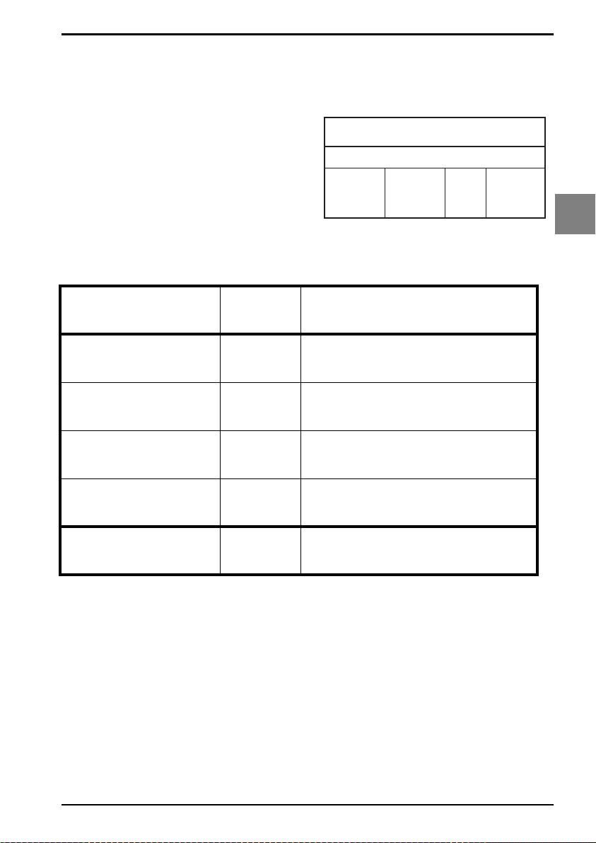
OPTICON UNIVERSAL MENU BOOK
3.3.14. Options for Korean Postal Authority
code
Korean Postal Authority code is a fixed length
numeric symbology with a mandatory check
digit. The check digit is not transmitted.
For string format see figure 3.35.
Options for Korean Postal Authority code:
• transmit dash
• not transmit dash
• transmit CD
• not transmit CD
Transmit dash:
The dash character '-' ( hex 2D ) is printed
between the 3rd and 4th digit
Fig. 3.35. Options for
Korean Postal Authority code
Korean Postal Authority code
check digit data
(3 digits)
dash
(-)
data
(3 digits)
3
Code options
Not transmit CD
Transmit CD
Not transmit dash
Transmit dash
SET
*-
*+
*/
*.
END
_ZZ_
_*-_
_*+_
_*/_
_*._
_ZZ_
U71
Page 78
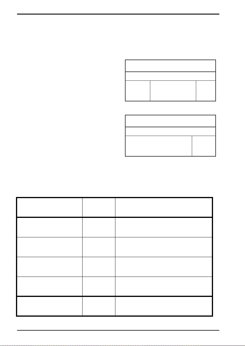
OPTICON UNIVERSAL MENU BOOK
3.3.15. Options for RSS
Support for these options is reader dependent.
Options for RSS:
• transmission of CD
• transmission of Application Identifier
Maximum data capacity:
• RSS-14 group and RSS limited: Application
Identifier "01" and 14 digits.
• RSS Expanded: 74 numeric or 41 alpha
characters
Checksums:
The RSS family uses a mandatory checksum.
The RSS-14 group uses a modulo 79
checksum, RSS Limited uses a modulo 89
checksum and RSS Expanded uses a modulo
211 checksum. The checksum is always
calculated and is not transmitted.
Encodable characters:
• RSS-14 group and RSS limited: digits 0 up to
9
• RSS Expanded: subset of ISO 646: upper,
lower case characters, digits, 20 punctuation
characters and function character FNC1
The next RSS versions are supported:
• RSS-14 including truncated, stac ked, stack ed
omni directional
• RSS Limited
• RSS Expanded, Expanded stacked
For string format see figure 3.36 or 3.37.
SET
Not transmit CD:
Do not transmit the last character of RSS.
Fig. 3.36. Options for RSS
RSS-14, RSS Limited
application
identifier (01)
Fig. 3.37. Options for RSS
(1 upto 73 characters)
data
(13 digits)
RSS Expanded
data
(1 digit)
cd
(1 character)
_ZZ_
cd
Not transmit CD
T ransmit CD
Not transmit Application
Identifier
Transmit Application
Identifier
DM
DL
DT
DS
END
_DM_
_DL_
_DT_
_DS_
_ZZ_
U72
Page 79
OPTICON UNIVERSAL MENU BOOK
3.3.16. Options for Composite Codes
CC-A is a modified MicroPDF417 version.
CC-B is standard MicroPDF417.
CC-C is standard PDF417.
Maximum data capacity:
• CC-A: 56 characters
• CC-B: 338 characters
• CC-C: 2361 characters
Symbol size:
• 1D part: see RSS and EAN codes
• Composite part: CC-A and CC-B same as
MicroPDF417, CC-C same as PDF417
Error correction:
• 1D part: only error detection
• Composite part: Reed Solomon error
correction
Encodable characters:
• ASCII values 0 - 127 ( ISO 646 )
• ASCII values 128 - 255 ( ISO 8859-1, Latin
alphabet No. 1, extended ASCII )
• with ECI: many other character sets
For string format of composite codes see figure
3.38 or 3.39 or 3.40.
Options for Composite codes:
• enable composite code
• ignore link flag
• output mode
For string format of composite codes see figure
3.41.
Fig. 3.38. Options for Composite Codes
Composite A
1D data
(1 upto 73 characters)
composite data
(1 upto 56 characters)
Fig. 3.39. Options for Composite Codes
Composite B
1D data
(1 upto 73 characters)
composite data
(1 upto 338 characters)
Fig. 3.40. Options for Composite Codes
Composite C
1D data
(1 upto 73 characters)
Fig. 3.41. Combined options
Fig. 3.40. Options for Composite Codes
Composite
Enable
(1 upto 73 characters)
for Composite Codes
Link
1D data
Flag
RP
RP
RP
RQ
RQ
RQ
RP
RP
RP
RQ
RQ
RQ
BHE
BHE
BHE
BHE
BHE
BHE
BHF
BHF
BHF
BHF
BHF
BHF
Composite C
composite data
(1 upto 2361 characters)
Output
Mode
BL0
BL1
BL2
BL0
BL1
BL2
BL0
BL1
BL2
BL0
BL1
BL2
Output
Result
1D / 1D+2D
composite data
2D / 1D+2D
(1 upto 2361 characters)
1D / 2D / 1D+2D
1D+2D
1D+2D
1D+2D
1D
2D
1D / 2D
1D
2D
1D / 2D
3
Code options
U73
Page 80

OPTICON UNIVERSAL MENU BOOK
3.3.16. Options for Composite Codes
Not ignore composite
link flag
Ignore composite link flag
Disable Composite on
RSS
Enable Composite on
RSS
As a single component,
only 1D component is
allowed
As a single component,
only 2D component is
allowed
As a single component,
only 1D+2D component
is allowed
SET
RQ
RP
BHF
BHE
BL0
BL1
BL2
END
_ZZ_
_RQ_
_RP_
_BHF_
_BHE_
_BL0_
_BL1_
_BL2_
_ZZ_
U74
Page 81

OPTICON UNIVERSAL MENU BOOK
3.3.17. Options for DataMatrix
Data Matrix is a variable size matrix symbology
with selectable error correction levels.
Maximum data capacity (ECC200):
• alphanumeric data: 2335 characters
• 8-bit data: 1556 characters
• numeric data: 3116 characters
Options for DataMatrix:
• Structured append time out: see chapter
Read options
Fig. 3.42. Options for DataMatrix
DataMatrix
Symbol size:
ECC000 - 140:
• odd number of rows and columns, square
shape.
• minimum: 9 * 9 modules, maximum: 49 * 49
modules
ECC200:
• e v en number of rows and columns, square or
rectangular shape
• square: minimum 10 * 10, maximum 144 *
144 modules
• rectangular: minimum 8 * 18, maximum 16 *
48 modules
Error correction:
• ECC000 - 140: four levels of convolutional
error correction, option for error detection
only
• ECC200: Reed-Solomon error correction
For new applications ECC200 is
recommended.
Additional features:
• extended Channel Interpretation (ECI,
ECC200 only): support for different character
sets and data interpretations
• structured append (ECC200 only): represent
data in up to 16 Data Matrix symbols
Support for these options is reader dependent.
The supported character set and the maximum
decodable number of characters, is reader
dependent
data
(1 upto 3116 characters)
3
Code options
Encodable characters:
• ASCII values 0 - 127 ( ISO 646 )
• ASCII values 128 - 255 ( ISO 8859-1, Latin
alphabet No. 1, extended ASCII )
• with ECI: many other character sets
For string format see figure 3.42.
U75
Page 82

3.3.18. Options for Aztec
OPTICON UNIVERSAL MENU BOOK
Aztec code is a variable size matrix symbology
with selectable error correction levels.
Maximum data capacity:
Standard Aztec:
• alphanumeric: 3067 characters
• numeric: 3832 characters
• byte: 1914 characters
Aztec runes:
• values 000 up to 255 ( 3 digits )
Symbol size:
Standard Aztec:
• minimum: 15 * 15 modules
• maximum: 151 * 151 modules
Aztec runes:
• fixed: 11 * 11 modules
Error correction:
User selectable Reed-Solomon error correction
levels from 5% to 95% of data region.
Additional features:
• extended Channel Interpretation (ECI):
support for different character sets and data
interpretations
• structured append: represent data in up to 26
Aztec symbols
• mirror image: decode symbol in mirror
reversal presentation
Support for these options is reader dependent.
The supported character set and the maximum
decodable number of characters, is reader
dependent
Fig. 3.43. Options for Aztec
Aztec
data
(1 upto 3832 characters)
Encodable characters:
• ASCII values 0 - 127 ( ISO 646 )
• ASCII values 128 - 255 ( ISO 8859-1, Latin
alphabet No. 1, extended ASCII )
• with ECI: many other character sets
For string format see figure 3.43.
Options for Aztec:
• structured append time out: see chapter
Read options
U76
Page 83

3.3.19. Options for QR Code
OPTICON UNIVERSAL MENU BOOK
QR code is a variable size matrix symbology
with selectable error correction levels.
Maximum data capacity:
Model 1:
• alphanumeric data: 707 characters
• 8-bit data: 486 characters
• numeric data: 1167 characters
• kanji data: 299 characters
Model 2:
• alphanumeric data: 4296 characters
• 8-bit data: 2953 characters
• numeric data: 7089 characters
• kanji data: 1817 characters
Symbol size:
Model 1:
• minimum: 21 * 21 modules
• maximum: 73 * 73 modules
Model 2:
• minimum: 21 * 21 modules
• maximum: 177 * 177 modules
Error correction:
Four levels of Reed-Solomon error correction.
Additional features:
• e xtended Channel Interpretation (ECI, model
2 only): support for different character sets
and data interpretations.
• structured append: represent data in up to 16
QR Code symbols.
Support for these options is reader dependent.
The supported character set and the maximum
decodable number of characters, is reader
dependent
Fig. 3.44. Options for QR Code
QR Code
data
(1 upto 7089 characters)
3
Code options
Encodable characters:
• ASCII values 0 - 127 ( ISO 646 )
• ASCII values 128 - 255 ( ISO 8859-1, Latin
alphabet No. 1, extended ASCII )
• with ECI: many other character sets
For string format see figure 3.44.
Options for QR code:
• structured append time out: see read mode
options
• no further options supported
U77
Page 84

3.3.20. Options for Maxicode
OPTICON UNIVERSAL MENU BOOK
Maxicode is a fixed size matrix symbology with
selectable error correction levels.
Maximum data capacity:
• alphanumeric data: 93 characters
• numeric data: 138 characters
Symbol size:
28.14mm wide * 26.91mm high ( including quiet
zones )
Error correction:
2 levels of Reed-Solomon error correction.
Additional features:
• extended Channel Interpretation (ECI):
support for different character sets and data
interpretations
• structured append: represent data in up to 8
Maxicode symbols
Support for these options is reader dependent.
The supported character set and the maximum
decodable number of characters, is reader
dependent.
Encodable characters:
• ASCII values 0 - 127 ( ISO 646 )
• ASCII values 128 - 255 ( ISO 8859-1, Latin
alphabet No. 1, extended ASCII )
• with ECI: many other character sets
For string format see figure 3.45.
Fig. 3.45. Options for Maxicode
Maxicode
data
(1 upto 138 characters)
Options for Maxicode:
• structured append time out: see read mode
options
• no further options supported
U78
Page 85

3.3.21. Options for PDF417
OPTICON UNIVERSAL MENU BOOK
PDF417 is variable size multi row (stacked)
symbology with selectable error correction
levels.
Maximum data capacity:
• text compaction: 1850 characters
• byte compaction: 1108 characters
• numeric compaction: 2710 characters
Symbol size:
• number of row: 3 up to 90
• number of columns: 1 up to 30
Error correction:
8 levels of error correction. Option for error
detection only.
Additional features:
• extended Channel Interpretation (ECI):
support for different character sets and data
interpretations
• macro PDF417: represent data in up to
99.999 PDF417 symbols
• truncated PDF417: reduce some ov erhead to
obtain smaller symbology size
Support for these options is reader dependent.
The supported character set and the maximum
decodable number of characters, is reader
dependent
Fig. 3.46. Options for PDF417
PDF417
data
(1 upto 2710 characters)
3
Code options
Encodable characters:
• ASCII values 0 - 127 ( ISO 646 )
• ASCII values 128 - 255 ( ISO 8859-1, Latin
alphabet No. 1, extended ASCII )
• for macro PDF417: many other character
sets
For string format see figure 3.46.
Options for PDF417:
• macro PDF417 timeout ( same as Structured
append time out ): see read mode options
• no further options available
U79
Page 86

3.3.22. Options for MicroPDF417
OPTICON UNIVERSAL MENU BOOK
MicroPDF417 is variable size multi row
(stacked) symbology with fixed error correction
levels.
Maximum data capacity:
• text compaction: 250 characters
• byte compaction: 150 characters
• numeric compaction:366 characters
Symbol size:
• number of row: 4 up to 44
• number of columns: 1 up to 4
Error correction:
Number of error correction codewords is
dependent of symbol size and can not be
changed.
Additional features:
• extended Channel Interpretation (ECI):
support for different character sets and data
interpretations
• macro MicroPDF417 ( structured append
mode ): represent data in up to 99.999
MicroPDF417 symbols
Support for these options is reader dependent.
The supported character set and the maximum
decodable number of characters, is reader
dependent
Fig. 3.47. Options for MicroPDF417
MicroPDF417
data
(1 upto 366 characters)
Encodable characters:
• ASCII values 0 - 127 ( ISO 646 )
• ASCII values 128 - 255 ( ISO 8859-1, Latin
alphabet No. 1, extended ASCII )
• for macro MicroPDF417: many other
character sets
For string format see figure 3.47.
Options for MicroPDF417:
• macro MicroPDF417 timeout ( same as
Structured append time out ): see read mode
options
• no further options available
U80
Page 87
OPTICON UNIVERSAL MENU BOOK
4. STRING OPTIONS
This chapter describes the alterations which
can be made to the format of the transmitted
data string.
Options available are:
• case conversion
• transmission of a code identifier
• transmission of the code length
• transmission of a prefix
• transmission of a suffix
The string format is transmitted as in figure
4.01.
The bar code data has the format as described
in chapter ‘Code Options’.
Fig. 4.01. String Options
preamble postambleprefix suffixbar code data
Note:
Preamble is the same as common prefix.
Postamble is the same as common suffix.
4
String options
U81
Page 88

4.1. Case conversion
OPTICON UNIVERSAL MENU BOOK
The bar code data may be converted to either
lower or upper case or the case may be
exchanged. These options may be used if the
user of a wedge has a preference to leave for
instance the CAPSLOCK on or if the host
requires upper case characters only . See figure
4.02.
SET
No case conversion
Convert to upper case
Convert to lower case
YZ
YW
YX
Fig. 4.02. Case conversion
AbCd Test string
AbCd No case conversion
ABCD Convert to upper case
abcd Convert to lower case
aBcD
Exchange case
_ZZ_
_YZ_
_YW_
_YX_
Exchange case
YY
END
_YY_
_ZZ_
U82
Page 89
OPTICON UNIVERSAL MENU BOOK
4.2. Set prefix and suffix
A prefix and suffix of maximum 4 direct input
entries each may be included in front and at the
end of the string respectively.
Bar code readers with an RS232 interface may
be programmed with all 128 ASCII characters.
Keyboard wedges may additionally be
programmed with the special keys supported
by the keyboard, e.g. function keys.
Default settings are:
• RS232: Prefix - None, Suffix - ^M (CR)
• Wedge: Prefix - None, Suffix - return
How to set a prefix or a suffix:
To configure a prefix for example for Code-39
as C39: scan the following labels from this
current chapter ‘String Options’:
<SET>
<Set prefix Code 39>
<C>
<3>
<9>
<:>
<END>
Bar code readers which do not support a
different prefix or suffix for each symbology
have to make use of <ALL>.
How to clear a prefix or suffix:
To clear the suffix for example for Code 128
scan the following labels:
<SET>
<Set suffix Code 128>
<END>
How to set a suffix for all symbologies:
To configure for example the suffix <CR> for all
symbologies scan the following labels:
<SET>
<Set suffix ALL>
<^M (CR)>
<END>
Note that this last example is for an RS232
interface. For a wedge interface a ^M (CR)
results in the key combination <ctrl>M.
If the direct input keyboard key <return> from
this chapter is selected then the result is a
<carriage return> or <Enter> key. See figure
4.03.
Fig. 4.03. Set prefix and suffix
PREFIX
SET
Set prefix Code 39
C
3
9
:
END
Preamble and postamble:
A preamble is transmitted before the prefix and
can contain up to 8 direct input characters. A
postamble is transmitted after the suffix and
can contain up to 8 direct input characters. A
preamble and postamble will be transmitted for
all symbologies. By default, the preamble and
postamble is empty.
Code identification Opticon:
A code identification and the code length may
be included as a prefix or suffix. The direct
input 'code identifier' provides a quick method
of programming in addition to programming a
separate prefix or suffix for each bar code type.
See figure 4.04.
Code identification AIM/ISO:
The Code identifier will be transmitted in the
ISO 15424 format : ]cm, where:
• ] is ASCII value decimal 93
• c is code character
• m is modifier character(s)
For a detailed list of the modifier character 'm'
and the AIM-ID’s, refer to the ISO15424
standard. See figure 4.05.
SUFFIX
SET
Set suffix Code 128
END
SET
Set suffix All
^M (CR)
END
4
String options
U83
Page 90

OPTICON UNIVERSAL MENU BOOK
In case the modifier is an asterix (*), the value
depends on the options of the symbology or on
the configured Code options. For details refer to
their own respective modifier tables. See
figures 4.06 up to 4.15.
Code length:
The code length is transmitted as 2 digits,
representing the decimal number of data
characters transmitted, excluding prefix and
suffix characters. For 2D bar codes the code
length is transmitted as 6 digits. It is also
possible to send for both 1D and 2D codes the
length as 6 digits.
These direct input characters count as 1 entry
of the 4 permissible entries for a prefix or suffix.
Example:
If you want to configure the prefix
<code identifier>:<code length>:
scan the following labels:
<SET>
<Set prefix all>
<Code identification>
<:>
<Code length>
<:>
<END>
If you want to use the code identifiers, but need
another code identifier for Code 39, you scan
the following labels:
<SET>
<Set prefix all>
<Code identification>
<:>
<Set prefix Code 39>
<$>
<:>
<END>
Fig. 4.04. Set prefix and suffix
OPTICON Code identifiers
UPC-A
UPC-A +2
UPC-A +5
UPC-E
UPC-E +2
UPC-E +5
EAN-13
EAN-13 +2
EAN-13 +5
EAN-8
EAN-8 +2
EAN-8 +5
Code 39
Code 39 Full ASCII
Italian Pharmaceutical
Codabar
Codabar ABC
Codabar CX
Industrial 2of5
Interleaved 2of5
S-Code
Matrix 2of5
IATA
MSI/Plessey
Telepen
UK/Plessey
Code 128
EAN-128
Code 93
Code 11
Korean Postal Authority code
RSS
CC-A
CC-B
CC-C
DataMatrix
Aztec
QR code
Maxi Code
MicroPDF417
PDF417
C
F
G
D
H
I
B
L
M
A
J
K
V
W
Y
R
S
f
O
N
g
Q
P
Z
d
a
T
T
U
b
c
y
m
n
l
t
o
u
v
s
r
U84
Page 91
OPTICON UNIVERSAL MENU BOOK
Fig. 4.05. Set prefix and suffix
AIM/ISO15424 Code identifiers
Symbology
UPC-A
EAN-13
UPC-E
UPC-A +2
UPC-A +5
UPC-E +2
UPC-E +5
EAN-13 +2
EAN-13 +5
EAN-8
EAN-8 +2
EAN-8 +5
Code 39 Full ASCII
Code 39 It. Pharmaceutical
Korean Postal Authority code
EAN-128 with CC-C
CC-A
(transmitted separately)
CC-B (transmitted separately)
CC-C (transmitted separately)
Code 39
Tri-Optic
Codabar
Codabar ABC
Codabar CX
Industrial 2of5
Interleaved 2of5
S-Code
Matrix 2of5
IATA
MSI/Plessey
Telepen
Code 128
EAN-128
Code 93
Code 11
RSS
RSS with CC-A
RSS with CC-B
PDF417
MicroPDF417
Data Matrix
Aztec
QR Code
Maxicode
]AIM-ID
*(Modifier table)
]E0
-
-
]E3
-
-
-
-
-
]E4
]E7
-
]A*
-
(4.06)
]X0
-
]F*
-
(4.07)
]X0
]S0
]I*
-
(4.08)
]X0
-
]R*
-
(4.09)
]M*
-
(4.10)
]X0
]B*
-
(4.11)
]C0
]C1
]G0
]H*
-
(4.12)
]X0
]X0
]e0
-
-
-
]e1
-
-
]L0
-
]d*
-
(4.13)
]z*
-
(4.14)
]Q*
-
(4.15)
]U*
-
(4.16)
Fig. 4.06. Modifiers for Code 39
AIM/ISO15424 Code identifiers for : A*
Code options
Normal Code 39 (D5)
Not check CD (C1)
Transmit CD (D9)
Normal Code 39 (D5)
Check CD (C0)
Transmit CD (D9)
Normal Code 39 (D5)
Not check CD (C1)
Not transmit CD (D8)
Normal Code 39 (D5)
Check CD (C0)
Not transmit CD (D8)
Full ASCII Code 39 (D4)
or Full ASCII Code 39 if pos. (+K)
Not check CD (C1)
Transmit CD (D9)
Full ASCII Code 39 (D4)
or Full ASCII Code 39 if pos. (+K)
Check CD (C0)
Transmit CD (D9)
Full ASCII Code 39 (D4)
or Full ASCII Code 39 if pos. (+K)
Not check CD (C1)
Not transmit CD (D8)
Full ASCII Code 39 (D4)
or Full ASCII Code 39 if pos. (+K)
Check CD (C0)
Not transmit CD (D8)
]AIM-ID
]A0
]A1
]A2
]A3
]A4
]A5
]A6
]A7
4
String options
U85
Page 92
OPTICON UNIVERSAL MENU BOOK
Fig. 4.07. Modifiers for Codabar
AIM/ISO15424 Code identifiers for : F*
Code options
Codabar normal mode (HA)
Not check CD (H7)
Transmit CD (H8)
Codabar ABC (H3 or H4)
Not check CD (H7)
Transmit CD (H8)
Codabar normal mode (HA)
Check CD (H6)
Transmit CD (H8)
Codabar ABC (H3 or H4)
Check CD (H6)
Transmit CD (H8)
Codabar normal mode (HA)
Not check CD (H7)
Not transmit CD (H9)
Codabar ABC (H3 or H4)
Not check CD (H7)
Not transmit CD (H9)
Codabar normal mode (HA)
Check CD (H6)
Not transmit CD (H9)
Codabar ABC (H3 or H4)
Check CD (H6)
Not transmit CD (H9)
]AIM-ID
]F0
]F1
]F2
]F3
]F4
]F5
]F6
]F7
Fig. 4.08. Modifiers for Interleaved 2of5
AIM/ISO15424 Code identifiers for : I*
Code options
Not check CD (G0)
Check CD (G1)
Not check CD (G0)
Check CD (G1)
Transmit CD (E0)
Transmit CD (E0)
Not transmit CD (E1)
Not transmit CD (E1)
]AIM-ID
]I0
]I1
]I2
]I3
Fig. 4.09. Modifiers for IATA
AIM/ISO15424 Code identifiers for : R*
Code options
Not check CD (4H)
Transmit CD (4L)
Check FC and SN only (4I)
or Check CPN,FC and SN (4J)
or Check CPN,AC,FC and SN (4K)
Transmit CD (4L)
Not check CD (4H)
Not transmit CD (4M)
Check FC and SN only (4I)
or Check CPN,FC and SN (4J)
or Check CPN,AC,FC and SN (4K)
Not transmit CD (4M)
]AIM-ID
]R0
]R1
]R2
]R3
Fig. 4.10. Modifiers for MSI/Plessey
AIM/ISO15424 Code identifiers for : M* / X0
Code options Checksum
Check 1 CD = MOD 10 (4B):
+ Transmit CD1
(4B)
+ Not transmit CD
(4B)
+ Transmit CD1 and CD2
(4B)
Check 2 CD's = MOD 10/ MOD 10 (4C):
(4C)
+ (4E) or (4G) or (4F)
Check 2 CD's = MOD 10/ MOD 11 (4D):
(4D)
+ (4E) or (4G) or (4F)
Check 2 CD's = MOD 11/ MOD 10 (4R):
(4R)
+ (4E) or (4G) or (4F)
+ Transmit
(4E)
(4G)
(4F)
]AIM-ID
]M0
]M1
]X0
]X0
]X0
]X0
Fig. 4.11. Modifiers for Telepen
AIM/ISO15424 Code identifiers for : B*
Code options
Telepen (numeric or ASCII only):
ASCII mode (D3)
Numeric mode (D2)
Telepen (numeric followed by ASCII):
ASCII mode (D3)
Numeric mode (D2)
Telepen (ASCII followed by numeric)(not supported):
ASCII mode (D3)
Numeric mode (D2)
]AIM-ID
]B0
]B1
]B0
]B2
]B0
]B2
U86
Page 93
OPTICON UNIVERSAL MENU BOOK
Fig. 4.12. Modifiers for Code 11
AIM/ISO15424 Code identifiers for : H* / X0
Code options
Check 1 CD (BLG)
or Check auto 1 or 2 CDs (BLI)
(length < 12)
Transmit CD(s) (BLK)
Check 2 CDs (BLH)
or Check auto 1 or 2 CDs (BLI)
(length > 12)
Transmit CD(s) (BLK)
Check 1 CD (BLG)
or Check 2 CDs (BLH)
or Check auto 1 or 2 CDs (BLI)
(length > 12)
Not transmit CD(s) (BLJ)
Not check CD (BLF)
Not transmit CD(s) (BLJ)
Fig. 4.13. Modifiers for DataMatrix
AIM/ISO15424 Code identifiers for : d*
Symbology, data structure
ECC000 - ECC140
ECC200
ECC200, FNC1 in 1st or 5th position
ECC200, FNC1 in 2nd or 6th position
ECC200, supporting ECI protocol
ECC200, FNC1 in 1st or 5th position and
supporting ECI protocol
ECC200, FNC1 in 2nd or 6th position and
supporting ECI protocol
]AIM-ID
]H0
]H1
]H3
]X0
]AIM-ID
]d0
]d1
]d2
]d3
]d4
]d5
]d6
Fig. 4.14. Modifiers for Aztec
AIM/ISO15424 Code identifiers for : z*
Data structure
No structure / other
FNC1 preceeding 1st message character
FNC1 following an initial letter or pair of digits
ECI protocol implemented
FNC1 preceeding 1st message character and
ECI protocol implemented
FNC1 following an initial letter or pair of digits,
ECI protocol implemented
Structured append header included
Structured append header included and
FNC1 preceeding 1st message character
Structured append header included,
FNC1 following an initial letter or pair of digits
Structured append header included and
ECI protocol implemented
Structured append header included,
FNC1 preceeding 1st message character,
ECI protocol implemented
Structured append header included,
FNC1 following an initial letter or pair of digits,
ECI protocol implemented
Aztec runes
Fig. 4.15. Modifiers for QR Code
AIM/ISO15424 Code identifiers for : Q*
Model, data structure
Model 1
Model 2, ECI protocol not implemented
Model 2, ECI protocol implemented
Model 2, ECI protocol not implemented,
FNC1 in first position
Model 2, ECI protocol implemented,
FNC1 in first position
Model 2, ECI protocol not implemented,
FNC1 in second position
Model 2, ECI protocol implemented,
FNC1 in second position
]AIM-ID
]z0
]z1
]z2
]z3
]z4
]z5
]z6
]z7
]z8
]z9
]zA
]zB
]zC
]AIM-ID
]Q0
]Q1
]Q2
]Q3
]Q4
]Q5
]Q6
4
String options
U87
Page 94

Fig. 4.16. Modifiers for Maxicode
AIM/ISO15424 Code identifiers for : U*
Data structure
Symbol in mode 4 or 5
Symbol in mode 2 or 3
Symbol in mode 4 or 5,
ECI protocol implemented
Symbol in mode 2 or 3,
ECI protocol implemented
OPTICON UNIVERSAL MENU BOOK
]AIM-ID
]U0
]U1
]U2
]U3
U88
Page 95
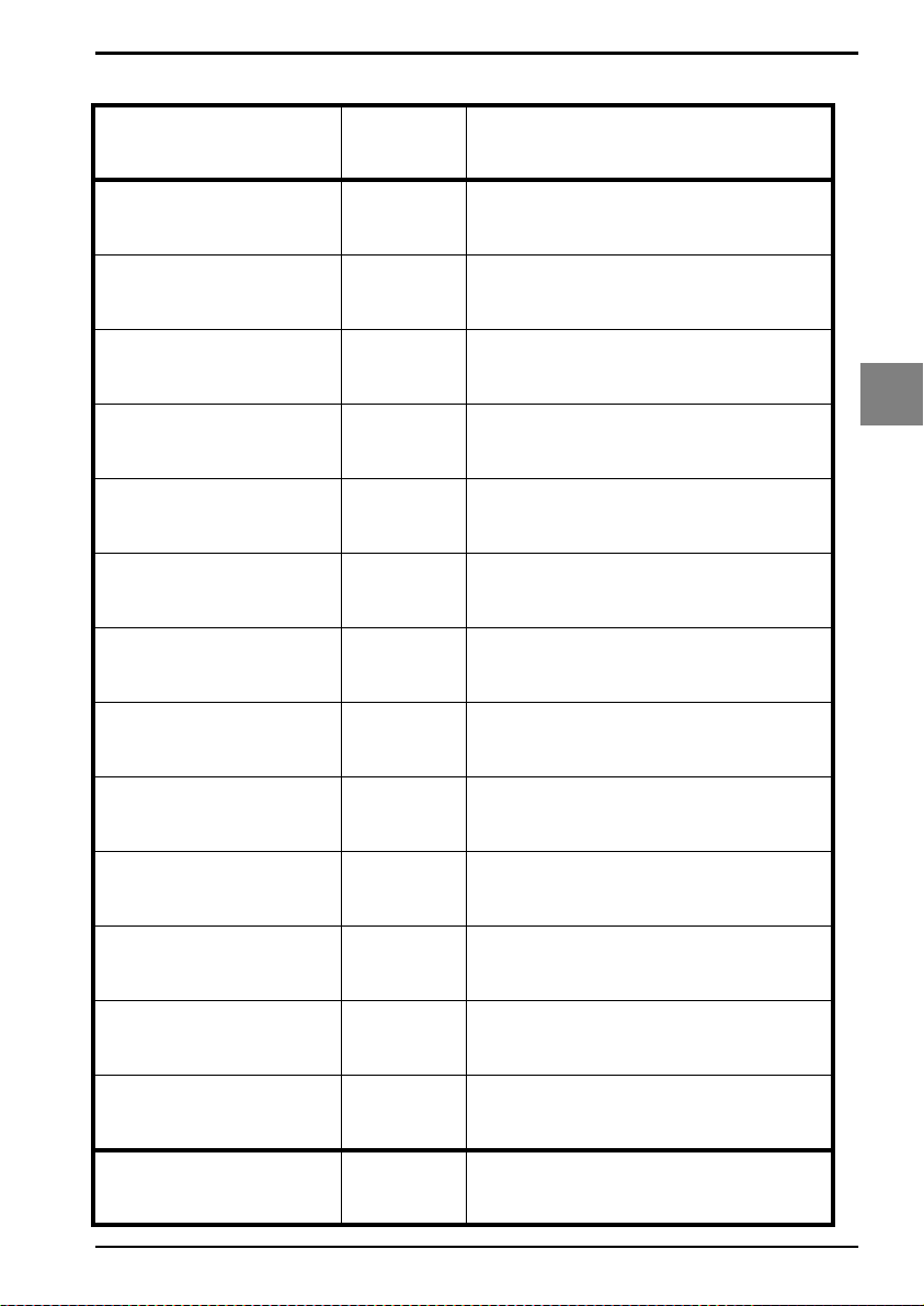
4.2.1. Set prefix
OPTICON UNIVERSAL MENU BOOK
All Codes
UPC-A
UPC-A + add on
UPC-E
UPC-E + add on
EAN-13
EAN-13 + add on
EAN-8
SET
RY
N1
M0
N2
M1
N3
M2
N4
_ZZ_
_RY_
_N1_
_M0_
4
String options
_N2_
_M1_
_N3_
_M2_
_N4_
EAN-8 + add on
Code 39
Codabar
Industrial 2of5
Interleaved 2of5
M3
M4
M5
M6
M7
END
_M3_
_M4_
_M5_
_M6_
_M7_
_ZZ_
U89
Page 96

OPTICON UNIVERSAL MENU BOOK
S-Code
Matrix 2of5
IATA
MSI/Plessey
Telepen
UK/Plessey
Code 128
Code 93
SET
MB
GL
I8
N0
L8
MA
M9
M8
_ZZ_
_MB_
_GL_
_I8_
_N0_
_L8_
_MA_
_M9_
_M8_
Code 11
Korean Postal Authority
code
RSS
Composite codes
DataMatrix
BLD
*$
OE
RR
MD
END
_BLD_
_*$_
_OE_
_RR_
_MD_
_ZZ_
U90
Page 97
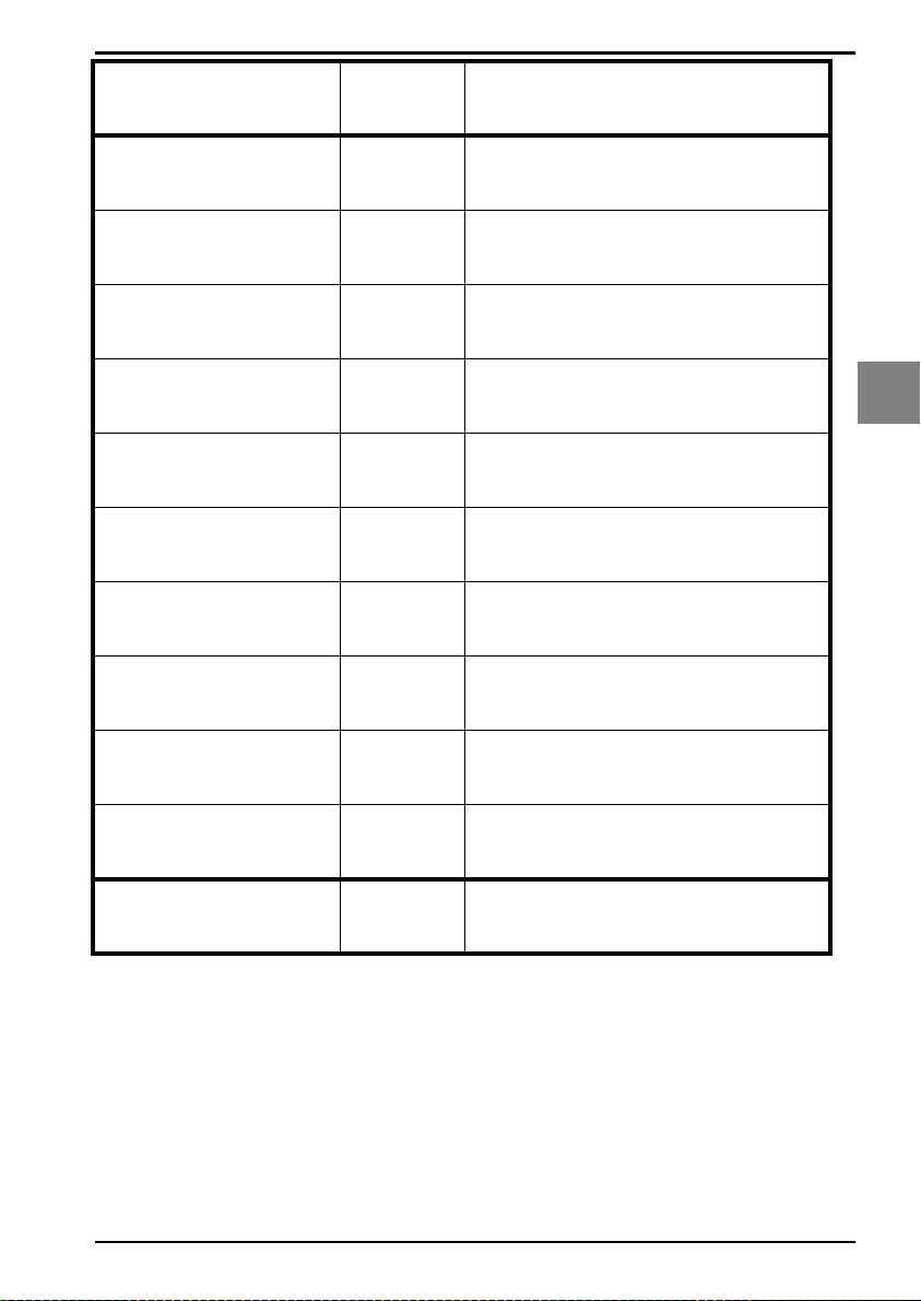
OPTICON UNIVERSAL MENU BOOK
Aztec
QR Code
Maxicode
PDF417
MicroPDF417
ISO track 1 (IATA)
ISO track 2 (ABA)
ISO track 3 (THRIFT)
SET
BF0
MK
ML
OC
OD
MH
MI
MJ
_ZZ_
_BF0_
_MK_
_ML_
_OC_
_OD_
_MH_
_MI_
_MJ_
4
String options
Clear all prefixes
Preamble
MG
MZ
END
_MG_
_MZ_
_ZZ_
U91
Page 98

4.2.2. Set suffix
OPTICON UNIVERSAL MENU BOOK
All Codes
UPC-A
UPC-A + add on
UPC-E
UPC-E + add on
EAN-13
EAN-13 + add on
EAN-8
SET
RZ
N6
O0
N7
O1
N8
O2
N9
_ZZ_
_RZ_
_N6_
_O0_
_N7_
_O1_
_N8_
_O2_
_N9_
EAN-8 + add on
Code 39
Codabar
Industrial 2of5
Interleaved 2of5
O3
O4
O5
O6
O7
END
_O3_
_O4_
_O5_
_O6_
_O7_
_ZZ_
U92
Page 99
OPTICON UNIVERSAL MENU BOOK
S-Code
Matrix 2of5
IATA
MSI/Plessey
Telepen
UK/Plessey
Code 128
Code 93
SET
OB
GM
I9
N5
L9
OA
O9
O8
_ZZ_
_OB_
_GM_
_I9_
_N5_
_L9_
_OA_
_O9_
_O8_
4
String options
Code 11
Korean Po stal Authority
code
RSS
Composite codes
DataMatrix
BLE
*%
PQ
RS
PO
END
_BLE_
_*%_
_PQ_
_RS_
_PO_
_ZZ_
U93
Page 100

OPTICON UNIVERSAL MENU BOOK
Aztec
QR Code
Maxicode
PDF417
MicroPDF417
ISO track 1 (IATA)
ISO track 2 (ABA)
ISO track 3 (THRIFT)
SET
BF1
PW
PX
PY
PZ
PT
PU
PV
_ZZ_
_BF1_
_PW_
_PX_
_PY_
_PZ_
_PT_
_PU_
_PV_
Clear all suffixes
Postamble
PR
PS
END
_PR_
_PS_
_ZZ_
U94
 Loading...