

Page 1
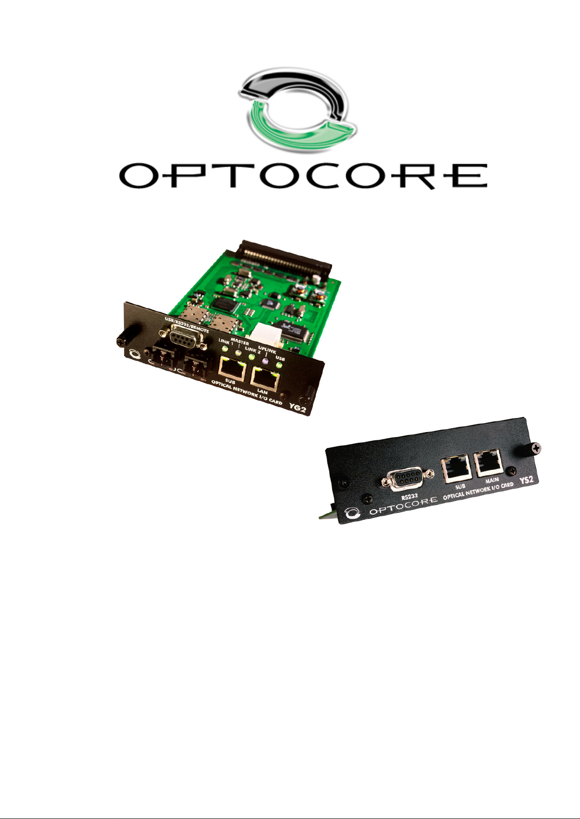
Operating Manual for OPTOCORE YG2/YS2
OPTICAL DIGITAL MINI - YGDAI CARDS FOR YAMAHA DEVICES
Optical Network I/O Cards
© Copyright 2007 All rights reserved
OPTOCORE GmbH
Lisbergstr. 7
81249 Munich
Germany
YG2 / YS2
Operating Manual
Rev. 1.1
Page 2
Important Safety Instructions
• Please read this manual carefully.
• Please keep this operating manual in a safe place.
• Heed all warnings.
• Follow all instructions.
• Do not use the cards near water, for example, in moist or damp rooms.
• Clean front only with a dry cloth.
• Install the cards in accordance to the operating manual.
• Do not place the cards near any heat source such as radiators, power-amplifiers, stoves, or
any other heat producing equipment.
• The cards may only be used in accordance to the information provided in this operating
manual. Ensure that all recommendations, especially the safety recommendations as
detailed in this operating manual, are followed before and during the usage of the cards.
• Do not place the cards on an unstable table, tripod, cart, etc. The cards may fall, causing
serious damage to the cards, and a risk of injury.
• Only use attachments specified by the manufacturer.
• The cards contain no user serviceable parts: only refer to authorized, qualified service
personnel for any servicing.
• Your warranty will be voided if you tamper with the internal components.
YG2 / YS2 2 / 2 Rev. 1.1
Page 3
Purchaser Information
• Operating Manual
Please read this manual – if you call for technical support, we’ll assume that you have. Study the
operating manual carefully in order to familiarize yourself with the cards and its operation. It
contains numerous information and hints for the proper use of the cards.
It cannot be excluded that this operation manual shows typographical mistakes or misprints; it is
however regularly revised.
Modifications, which serve the purpose of technical improvement of the cards, may be carried out
without prior notification.
• Transport and Shipping
Always ensure the careful handling of the cards. If not mounted in a console or other Yamaha
device, leave and transport the cards in the ESD bag, in which they have been delivered. Use
special, shock-absorbing cardboard boxes or transport cases for transport and shipping. The cards
may be transported while mounted in a desk.
• Handling
To prevent damage through electrostatic discharge (ESD) do not touch the electrical components
directly. While inserting the cards into the slot of a console, hold the cards at its front panel or by the
use of rack mount screws.
• Environments
This device can be used in E1, E2, E3, E4, or E5 environments (as listed below) according to the
harmonized European standards EN55103-1 and EN55103-2 “Electromagnetic compatibility –
Product family standard for audio, video and audio-visual and entertainment lighting control
apparatus for professional use”
E1-Residental
E2-Commercial and light industrial
E3-Urban outdoors
E4-Controlled EMC environment e.g. broadcast and TV-studio
E5-Heavy industry
The product is intended for the use in moderate climate.
• Water and Moisture etc.
To prevent fire or shock hazard do not expose cards to the effects of direct sunlight, dust, water, or
rain during operation or storage.
• Cleaning
Do not clean or touch the electrical components of the cards. Only use a dry linen cloth to clean the
front panel of the cards. In case of strong soiling, moisten the cloth using a little water and a small
amount of household detergent. Never use cleansing agents containing solvents to clean the cards.
Avoid water or moisture to come in contact with electrical components.
• Operating and Storage Temperature
Operating temperature: 0°C …50°C • 34°F …122°F, ensure proper ventilation
Storage temperature: -20°C …60°C • -4°F …140°F
• Power Supply
The console in which the card is mounted provides power supply and grounding.
YG2 / YS2 3 / 3 Rev. 1.1
Page 4
• Lightning
For additional protection of the cards during lightning storms, or when they are left unattended and
unused for a long period of time, unplug the power line of the console. This will prevent damage to
the cards due to lightning and power line surges.
• Eye Safety
This product is a Laser Class 1 product. It complies with IEC 60825 -1, FDA 21 CFR 1040.10, and
1040.11.
• Interference of external objects and/or liquids with the cards
Never push objects of any kind into the cards. They may come in touch with dangerous voltage
points or short out parts that could result in a fire or electric shocks. Never spill liquid of any kind on
the cards.
• Cables and Accessories
Only use attachments specified by the manufacturer.
Only use high quality cable material to connect the cards. For the optical data connection
exclusively use the specified optical waveguide cables. If not in use, ensure that the optical
connectors of both, card and waveguide are closed with the provided lids.
Do not place the cards on an unstable table, tripod, cart, etc. The cards may fall, causing serious
damage to them, and to injury. Any mounting of the cards should follow the manufactures
instructions and should use mounting accessory recommended by the manufacturer.
• Servicing
Do not attempt to service the cards yourself.
Qualified personnel can change the optical transceivers. Before any attempt to alter the
transceivers, please contact your dealer / distributor for instructions. Besides that the cards contain
no user serviceable parts: please do only refer to authorized, qualified service personnel for any
servicing.
The cards may not be serviced, altered or modified without authorization of Optocore or an
Optocore authorized dealer / distributor. Qualified service personnel may only carry out repair and
maintenance work. The warranty will be voided if unauthorized manipulation occurred.
YG2 / YS2 4 / 4 Rev. 1.1
Page 5
CE-Conformity
This document confirms that the product YG2 and YS2 bearing the CE (Communauté Européenne) label meets
all requirements in the EMC directive 2004/108/EG laid down by the Member States Council for adjustment of
legal requirements. Furthermore the product complies with the rules and regulations of the low-voltage directive
2006/95/EG. This product bearing the CE label complies with the following standards, ratified by CENELEC
(Comité Européen de Normalisation Electrotechnique):
Electromagnetic compatibility – Product family standard for audio, video, audio-visual and
entertainment lighting control apparatus for professional use
EN 55103-1, Emission
EN 55103-2, Immunity
The authorised declaration and compatibility certification lies with the manufacturer and can be viewed on
request. Responsible as manufacturer is:
OPTOCORE GmbH, Lisbergstr.7, 81249 Munich, Germany
represented by Marc Brunke, Managing Director
N.B. The awarding of the CE label confirms the compliance with legal directives issued for the manufacture and
marketing of electronic and electrical devices. As such the CE label is not a "seal of quality" but rather proof that
the device bearing the CE label is conform with the electromagnetic compatibility standards laid down in the
above named testing regulations.
Munich, 01.07.2007
Marc Brunke
Eye Safety
This product is a Laser Class 1 product. It complies with IEC 60825-1 and FDA 21 CFR 1040.10
and 1040.11.
YG2 / YS2 5 / 5 Rev. 1.1
Page 6
YG2 / YS2 Optical Digital Mini - YGDAI Cards for Yamaha Devices
Table of Contents
Important Safety Instructions...........................................................................................................................2
Purchaser Information ................................ ................................ .....................................................................3
CE-Conformity .................................................................................................................................................5
Eye Safety.......................................................................................................................................................5
Device Description................................................................................................................................ ........... 7
Front Panel YG2................................ ................................ ..............................................................................8
YG2 Cards Details...........................................................................................................................................9
Digital Audio................................................................................................................................ .........9
LC-Connectors......................................................................................................................................9
HA Remote...........................................................................................................................................9
USB/RS232/REMOTE Auxiliary Port..................................................................................................... 9
LAN Port................................................................................................................................ ............... 9
SUB Port ..............................................................................................................................................9
RS232-Connection................................................................................................................................ 9
USB-Connection ...................................................................................................................................9
Protocol................................................................ ................................ ................................................9
Transmission Delay ................................ ................................ ..............................................................9
Control................................................................ ................................ ................................................10
Front Panel YS2................................................................................................................................ ............10
YS2 Cards Details ................................................................ ................................ .........................................10
Digital Audio................................................................................................................................ .......10
SUB Port ............................................................................................................................................10
Starting Up....................................................................................................................................................11
Software Installation ........................................................................................................................... 11
Hardware Connection..........................................................................................................................11
Optocore Network Setup................................................................ .....................................................11
Network Example................................................................................................................................13
Device Compatibility ................................................................ ...........................................................14
Connection Tables.........................................................................................................................................15
YG2 Cards D-SUB9 Connector ...........................................................................................................15
YS2 Cards D-SUB9 Connector............................................................................................................15
Technical Specifications ................................................................................................................................16
YG2 Card ...........................................................................................................................................16
YS2 Card................................................................................................ ................................ ............16
Dimensions and Weight.................................................................................................................................17
Warranty.......................................................................................................................................................18
Shipping Contents ................................................................................................ .........................................18
Company Information....................................................................................................................................19
YG2 / YS2 6 / 6 Rev. 1.1
Page 7
Device Description
Congratulations on your purchase of an YG2 / YS2 Optical Digital Mini - YGDAI Card. The YG2 / YS2 cards will
quickly convince you with their advantages and will facilitate your day -to-day work with Yamaha consoles and
devices such as the PM or DM series devices. YG2 / YS2 cards offer a broad flexibility in all sorts of temporary
and permanent applications, especially when long distance connections, high-quality audio transmission,
extremely low latency or high security is required.
The main card YG2 allows a direct connection of Yamaha consoles with the OPTOCORE ® OPTICAL DIGITAL
NETWORK SYSTEM. The YG2 card is capable to insert up to 64 audio channels IN and extract 64 audio
channels OUT of the Optocore network simultaneously. Inserted into the device slot the YG2 exchanges a
maximum of 16IN / 16OUT audio channels according to the Yamaha Mini - YGDAI standard with the device.
Additional YS2 sub cards can be inserted into the remaining slots. Connected to an YG2 card via CAT5 cables
using the RJ45 “SUB” port, the YS2 cards increase the number of audio channels available at the Yamaha
device up to 64IN / 64OUT (32IN / 32OUT @ 96kHz) per YG2 card. Each YS2 card also exchanges a maximum
of 16IN / 16OUT audio channels according to the Yamaha Mini - YGDAI standard with the device.
YG2 and YS2 cards can be switched between 8/16-channel mode on the Mini - YGDAI slot via software. Up to 3
YS2 cards can be connected to an YG2 card in 16-channel mode, up to 7 YS2 cards in 8-channel mode. Please
refer to Chapter “Device Compatibility” for more information regarding the compatibility of your console or
device.
A number of YG2 cards can be inserted into the slots of one device to extend the number of channels handed
over to the Optocore network, e.g. a maximum of 128IN and 128OUT by inserting two YG2 cards in an Yamaha
PM1D system.
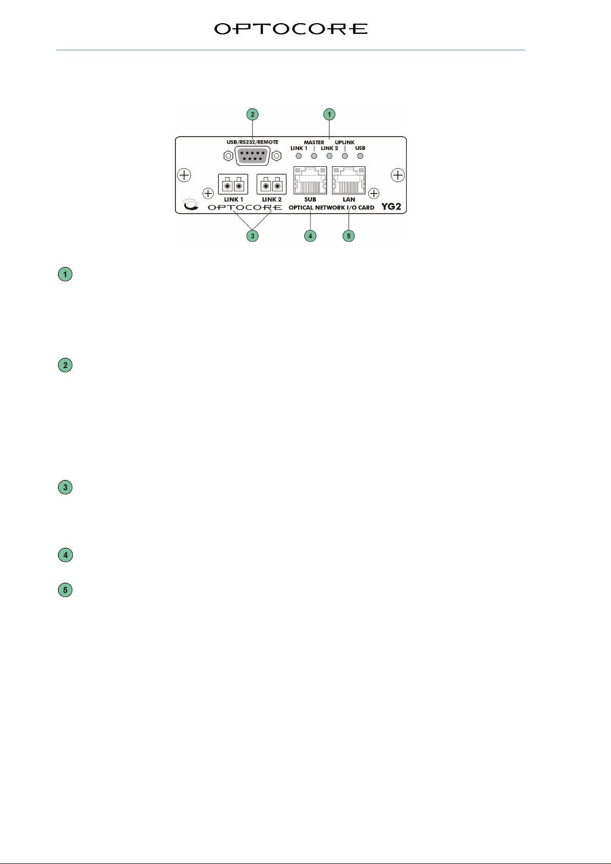
The YG2 front panel offers several outstanding features:
• Two LC-type optical interfaces for data transmission into the Optocore network and connection of
any Optocore device for instance the DD32(E), PTP32E, LX4AP.
• One RJ45 LAN port for connection of any standard 10/100MBit Ethernet device, transport of control
or any Ethernet compatible data via the Optocore network.
• USB/RS232/Remote (D-Sub-9) port for remote control, software update, connection of external PC,
and 2 x RS422 e.g. for transport of Yamaha Remote Protocol to AD8HR by a link to the HA Remote
interface of the console.
• Direct pick up of HA Remote signals from the console slot e.g. provided in Yamaha LS9 series.
• One RJ45 SUB port for connection of additional YS2 cards.
The YS2 front panel includes:
• RS232 port for upgrading via PC.
• One RJ45 SUB port for connection of the MAIN port of additional YS2 cards via CAT5 cable.
• One RJ45 MAIN port for connection of the SUB port of additional YS2 or YG2 cards via CAT5 cable
The YG2 / YS2 cards and any other Optocore device on stage e.g. LX4AP linked by a fiber optical cable can
easily replace an analog multi-conductor cable, weighting only a fraction of a conventional copper cored one. In
‘Yamaha Mode’ the YG2 / YS2 cards allow the gain control of Optocore microphone preamps on stage, as
provided in LX4AP or X6P-Series, using a Yamaha FOH digital console.
Due to SMD production the YG2 / YS2 cards fulfils the demand of highest digital standards. The FPGA (field
programmable gate array) based concept of the internal logic circuitry, permits updating of the hardware via the
units remote ports, ensuring continual state-of-the-art cards.
Through the USB or RS232 port of the YG2 card OPTOCORE CONTROL software can control the entire
Optocore network. OPTOCORE CONTROL software is used to change the configuration or define own settings.
It provides easy access to all configuration and control tools, including routing, naming, gain setting, and
phantom power activation for attached devices such as LX4AP and X6, storage and recall of configurations on
the computer, off- and online mode, real-time level display of the individual channels in online mode.
YG2 / YS2 7 / 7 Rev. 1.1
Page 8
Front Panel YG2
Link 1 LED: Communication to any other Optocore device is established via LINK 1
Master LED: Indicates that the unit is word clock master of the Optocore network
Link 2 LED: Communication to any other Optocore device is established via LINK 2
Uplink LED: Ethernet communication is established to another Optocore device capable
of Ethernet transport
USB LED: Communication to a locally connected PC is established via USB port
USB/RS232/REMOTE: D-Sub-9 plug containing following interfaces:
RS232 port for remote control and update via PC
USB port for remote control via PC
2 x RS422 ports e.g. for Yamaha HA Remote protocol exchange with
console
Use the TRI-Y cable, provided with the YG2 card. See chapter “Connection
Tables” for detailed pin out. For updating via PC a standard RS232 cable is
sufficient.
LINK 1: Full-duplex, full bandwidth LC-type optical interface for data transmission
(optical transceiver is changeable)
LINK 2: Full-duplex, full bandwidth LC-type optical interface for data transmission
(optical transceiver is changeable)
SUB: RJ45 port for connection towards the YS2 cards “SUB” port with CAT5 cable
LAN: RJ45 port for connection of any standard 10M/100M Ethernet device
YG2 / YS2 8 / 8 Rev. 1.1
Page 9
YG2 Cards Details
Digital Audio
The YG2 digital audio interface is located on the console slot connector. According to the Yamaha Mini - YGDAI
standard, the YG2 card features a maximum of 16IN / 16OUT audio channels. Using the OPTOCORE
CONTROL software the card can be switch to 8 channel mode for Yamaha devices providing 8IN / 8OUT audio
channels, such as the DIO8. (Please refer to chapters “Optocore Network Setup” and “Device Compatibility”)
LC-Connectors
The dual, 1Gbps full bandwidth optical interfaces are equipped with LC-connectors, commonly used and
absolutely reliable under normal conditions. For rough applications such as touring and rental the 1U OptoCon
panel, with rugged and secure fiber optic connectors can be added to a side rack.
HA Remote
The YG2 card supports direct pick up of HA Remote signals from the console slot e.g. provided in Yamaha LS9
series. If the console does not provide the HA Remote signal on the console slot, the signal can be applied
externally to the USB/RS232/REMOTE port.
USB/RS232/REMOTE Auxiliary Port
Two RS422 digital channels with a data transfer rate of up to 1Mbps are provided via D-SUB-9 connector on the
front panel. The two channels are software patchable to any Optocore device featuring RS485/RS422 auxiliary
ports. The Yamaha HA Remote protocol can be applied from the consoles external HA Remote port and
transported to any device in the Optocore network by using the provided TRI-Y cable, enabling the connection
and remote control of Optocore or Yamaha converters directly from the console.
LAN Port
A 10/100 Mbps Fast Ethernet interface is provided via RJ45 port. All LAN ports of the Optocore devices within
the Optocore network form a virtual switch with physically distributed ports. We recommend using a standard
CAT5 network cables to connect any Ethernet device such as a standard Ethernet switch for local distribution.
SUB Port
The SUB port offers the possibility to extend the number of channels transmitted to the console if connected to
the MAIN port of an YS2 card using a standard CAT5 cable.
RS232-Connection
A RS232 port is provided within the D-SUB-9 connector on the front panel. It can be used to upgrade the cards
internal logic or to connect it with the OPTOCORE CONTROL software. We recommend using a shielded,
standard 1:1 cable for the RS232 port.
USB-Connection
The D-SUB9 connector also provides an USB port. We recommend using the TRI-Y cable, which is provided
with every YG2 card. It allows you to connect with the OPTOCORE CONTROL software.
Please note: Upgrading the cards internal logic is only possible using the RS232 connection.
Protocol
The OPTOCORE ® OPTICAL DIGITAL NETWORK SYSTEM uses a digital Time Division Multiplex technology
(TDM) with a fiber channel based 8B10B-NRZI-coding. Static time slots guarantee the synchronous
transmission of all channels at any time with no demand for dynamic bandwidth.
Transmission Delay
The Optocore system delay, including the matrix, is fixed to 41,6 µs for all channels. The transport delay per
Optocore unit (<200 ns) in the network is insignificant. The transmission delay is c onstant from any point to any
point. Overall delay depends on converters and fiber cable length, with ‘normal’ cable lengths of <700 m it can
also be considered as marginal.
YG2 / YS2 9 / 9 Rev. 1.1
Page 10
Control
Controlling of all devices in the Optocore network including Optocore converter modules is achieved from any
unit using the OPTOCORE CONTROL software via RS232 or USB port. Both ports are available using D-SUB-9
connector on the front panel. If previously adapted by Optocore, third party protocols for card controlling can be
activated via OPTOCORE CONTROL menu SET / SPECIAL MODE, for example the "Yamaha mode" to control
the Optocore mice-preamps from a Yamaha-console.
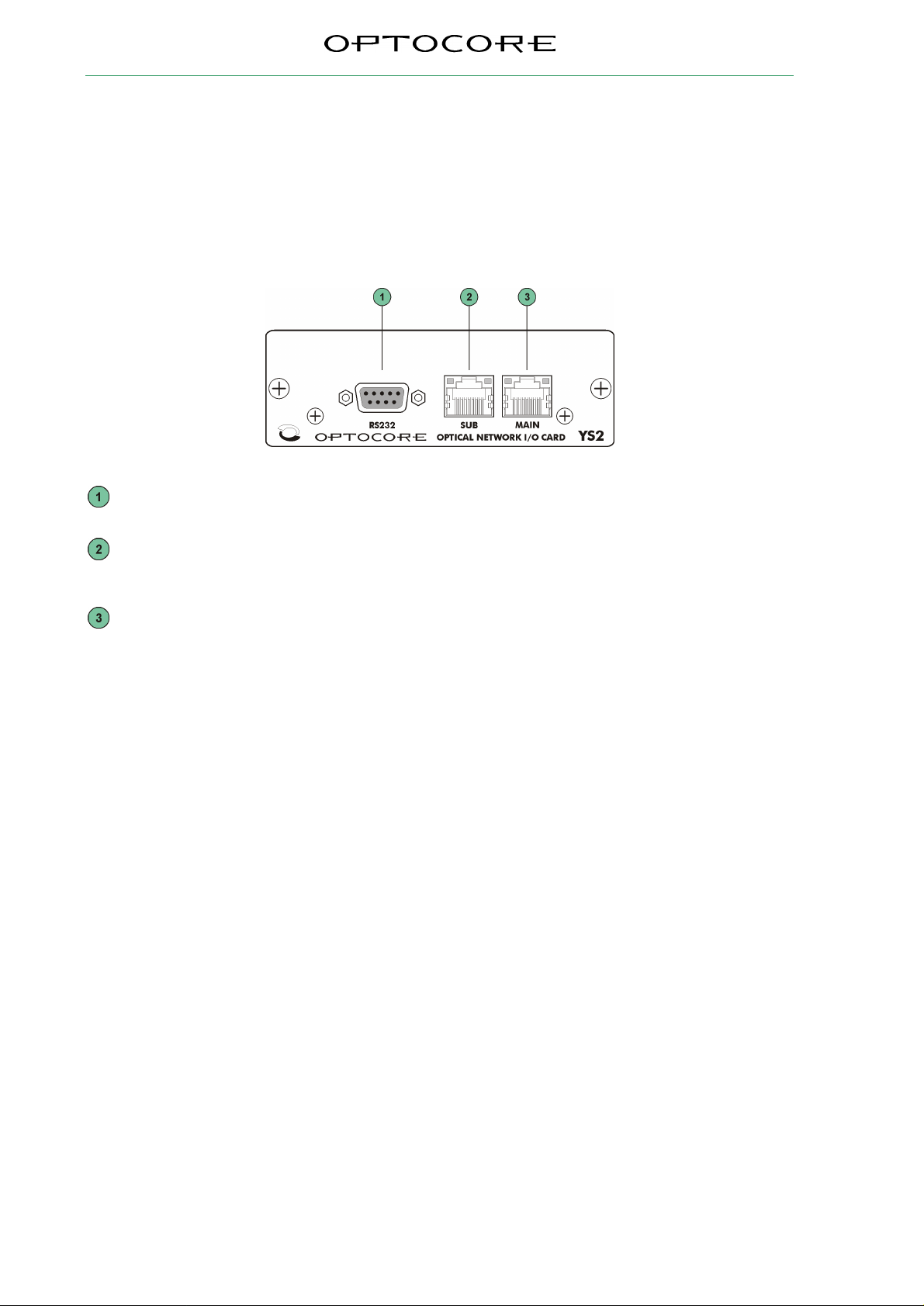
Front Panel YS2
RS232 plug: RS232 port for upgrading the cards internal logic via PC
SUB port: RJ45 port for connection towards the MAIN port of YS2 card with CAT5
cable
MAIN port: RJ45 port for connection towards the SUB port of a YG2 or YS2 card with
CAT5 cable
YS2 Cards Details
Digital Audio
The YS2 digital audio interface is located on the console slot connector. According to the Yamaha Mini - YGDAI
standard the YS2 card features a maximum of 16IN / 16OUT audio channels. Using the OPTOCORE
CONTROL software the card can be switch to 8 channel mode for Yamaha consoles providing 8IN / 8OUT
audio channels, such as the DIO8. (Please refer to chapters “Optocore Network Setup” and ”Device
Compatibility”)
SUB Port
The SUB port offers the possibility to extend the number of channels transmitted to the console if connected to
the MAIN port of an YS2 card using a standard CAT5 cable.
MAIN Port
The MAIN port is connected to the SUB port of an YG2 card. In a chain of several YS2 cards it is connected to
the SUB port of the next YS2 card towards direction of the YG2 card.
YG2 / YS2 10 / 10 Rev. 1.1
Page 11
Starting Up
In order to install the YG2 / YS2 Mini - YGDAI cards, proceed as follows:
Make sure that the power is turned off. Loosen the screws that hold the slot cover and remove the slot cover.
Keep the slot cover in a safe place. Match the edges of the card with the guardrails inside the slot and insert the
card. Push the card all the way into the slot ensuring that the connector at the end of the card is correctly mated
with the connector inside the slot. Use the screws included with the card to fasten the card in place.
Malfunctions or incorrect operation may occur if the card is not fixed correctly.
Software Installation
Installation requirement for the software is a functioning computer system with Microsoft Windows
95/98/2000/NT/XP/Vista ope rating system. The computer should be equipped with an USB interface for
configuration and remote controlling, and a RS232 interface (or an appropriate USB / RS232 adapter) for
firmware upgrade. COM 1...4 can be used with a transfer rate of 57 600 Baud. Monitor resolutions of 800 x 600
or 1024 x 768 with 16 Bit color rendering are recommended to view the program. The installation requires
approx. 2.5MB of hard-disk space and is carried out in the usual Windows -program manner.
Please note that the serial interfaces on computers are not usually capable of “Hot Plugging”. Switch
off the computer to avoid damage before establishing the serial connection between the Optocore
device and the computer.
The set-up software OCSETUPXXX.EXE is available on CD or can be downloaded from www.optocore.com.
OPTOCORE CONTROL for configuration and remote controlling, and OPTOCORE UPGRADE for firmware
upgrading are installed on a PC or Laptop by double-clicking on the OCSETUPXXX.EXE. The set-up executable
program is self-extracting and provides the OPTOCORE CONTROL SETUP WIZARD. It will establish the
necessary directories, a desktop icon for the OPTOCORE CONTROL and firmware upgrade software.
The uninstall procedure of OPTOCORE CONTROL can be carried out with the ADD OR REMOVE PROGRAMS
tool of Windows, which is usually found under START / CONTROL PANEL.
For details about features and handling of OPTOCORE CONTROL please refer to the HELP menu of the
software. We strongly recommend getting familiar with the OPTOCORE CONTROL software.
Hardware Connection
To get the YG2 / YS2 card system going, please be sure that the main power of the console is turned off before
inserting the cards into the Mini - YGDAI slots. Please refer to your consoles manual for detailed information.
Interconnect all cards with the provided CAT5 cables using the SUB / MAIN interfaces as shown in the chapter
”Optocore Network Setup”. Connect the provided TRI-Y cable for the Optocore network setup via USB port. Do
not connect the optical cables yet.
Optocore Network Setup
Before connecting the YG2 card to further Optocore devices by the optical LINK, assure that all devices have a
basic set-up in order to be able to operate correctly. For operation safety reasons, some settings (e.g. “ID”) are
only allowed to be made when locally connected to a device. The best approach to check the settings is to
connect locally to every single device of the Optocore network with a PC using either RS232 or USB connection
(use the provided TRI-Y Cable for USB), run the OPTOCORE CONTROL software and enter menu SET /
LOCAL SETTINGS.
The following descriptions only relate to YG2 / YS2 cards settings:
YG2 / YS2 11 / 11 Rev. 1.1
Page 12
YG2 Card
• General -> ID: Set each device in the opt ical network to a unique ID. Device IDs must be unique in
the entire Optocore network. Set the YG2 card inserted in the main console (when using several
consoles) to ID1 and check the “Master Priority” flag. This determines the card to be the internal
word clock master for the Optocore network.
• General -> Card ID: Set the ID to either “MY-16AT emulation” or “MY-8AT emulation” depending on
the standards of the console. Please refer to the chapter “Device Compatibility” which settings apply
for your console.
• HA Remote via slot: Choose the device ID and port of the destination device to which the
HA Remote signal should be transmitted. You can only choose the transmit port, the receive port is
assigned automatically. Due to the RS422 standard the two ports are unidirectional. For a bidirectional communication between the devices one transmit and one receive path has to be
determined. Make sure that both ports of the destination device match the setting of the YG2 card!
• HA Remote via f ront-panel-RS422: If your console does not provide the HA -remote signal on the
console slot, choose the destination device ID and its port, to which the HA-Remote Signal should
be transmitted and apply the HA-remote signal externally using the provided TRI-Y cable You can
only choose the transmit port, the receive port is assigned automatically. Due to the RS422
standard the two ports are unidirectional. For a bi-directional communication between the devices
one transmit and one receive path has to be determined. Make sure that both ports of the
destination device match the setting of the YG2 card!
• Ethernet setup: In order to use the Optocore network for Ethernet transport, the option has to be
activated at every device in the Optocore Network. Currently the Optocore network is capable to
transport three CVBS Video channels or one CVBS Video channel plus 100 Mbps Fast Ethernet
when Ethernet transport is activated. For the YG2 card the activation is done by marking the two
boxes “Optocore Ethernet transport” and “Enable local Ethernet”.
• SUB Setup -> SUB Cards: Set the number of YS2 cards, you have connected to your YG2 card.
Push button “Write” first, confirm with “OK” and press “Close” to exit the dialog.
YS2 Card
• General -> Card ID: Set it either to “MY-16AT emulation” or “MY-8AT emulation” depending on the
standards of the console. Please refer to chapter “Device Compatibility” which settings to use for
your console.
Push button “Write” first, confirm with “OK” and press “Close” to exit the dialog.
Check your console if all cards inserted in the slots have been recognized correctly (please refer to your
consoles manual how to do). If you have changed the default settings for “Card ID”, a restart of your console is
necessary after the change in order to recognize the cards correctly.
You may now connect the optical LINK cables between all Optocore devices.
Note: When connecting the optical LINK cables, for convenience temporarily remove the TRI-Y cable. This
especially counts for removing the optical cables.
Check your set-up by connecting to any device using either RS232 or USB connection, running the OPTOCORE
CONTROL software and starting “Online Mode” in the “Set” menu. The entire network at its current state is now
displayed in the control software. Check the “log window” for any error messages.
Optionally you may connect the TRI-Y cable to the HA Remote port of your console and attach any Ethernet
device to the LAN port of your YG2 card.
YG2 / YS2 12 / 12 Rev. 1.1
Page 13
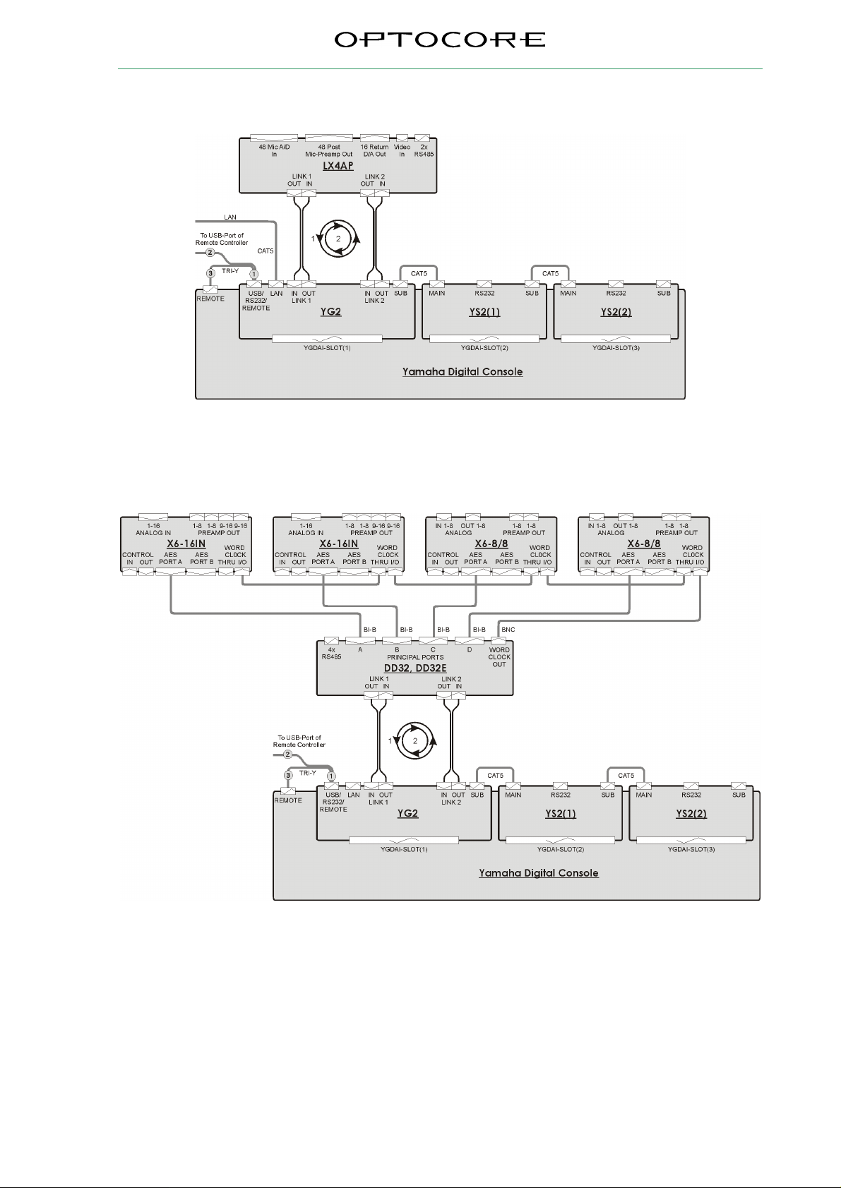
Network Example
Fig. 1: Example for an Optocore network with LX4AP on stage. Direct Control of LX4AP head amplifiers
from the console is achieved by switching the YG2 card into Yamaha Emulation Mode (YEM) using
OPTOCORE CONTROL.
Fig. 2: Wiring of a system with DD32(E), X6-converter units and a Yamaha console with YG2/YS2 cards.
In order to control the X6-converter at the console the Yamaha Emulation Mode (YEM) must be
activated in OPTOCORE CONTROL. Yamaha preamps connected to the DD32(E) will use the fiber
optical connection only for the bi-directional transfer of RS485 data and no special mode is activated.
YG2 / YS2 13 / 13 Rev. 1.1
Page 14
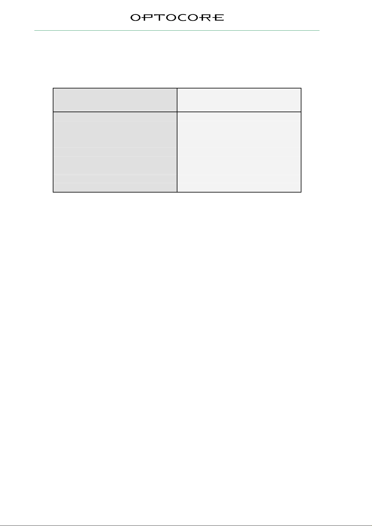
Device Compatibility
The table below lists Yamaha consoles and devices by the number of IN / OUT audio channels supported on
one console slot. Set the YG2 / YS2 cards either to “MY-16AT emulation” or “MY-8AT emulation” according to
the number of channels supported.
16 IN / 16 OUT
MY-16AT
1 YG2 plus 3 YS2 = 64 IN / 64 OUT
PM5D / PM5D-RH DIO8 for PM1D / PM1DV2
M7CL Series DME32
LS9 Series (with HA remote transport via slot) AD824
DM2000 DA824
DM1000
02R96
01V96
DME64N / DME24N
All future products with Mini - YGDAI slots
1 YG2 plus 7 YS2 = 64 IN / 64 OUT
8 IN / 8 OUT
MY-8AT
YG2 / YS2 14 / 14 Rev. 1.1
Page 15
5
1
5
1
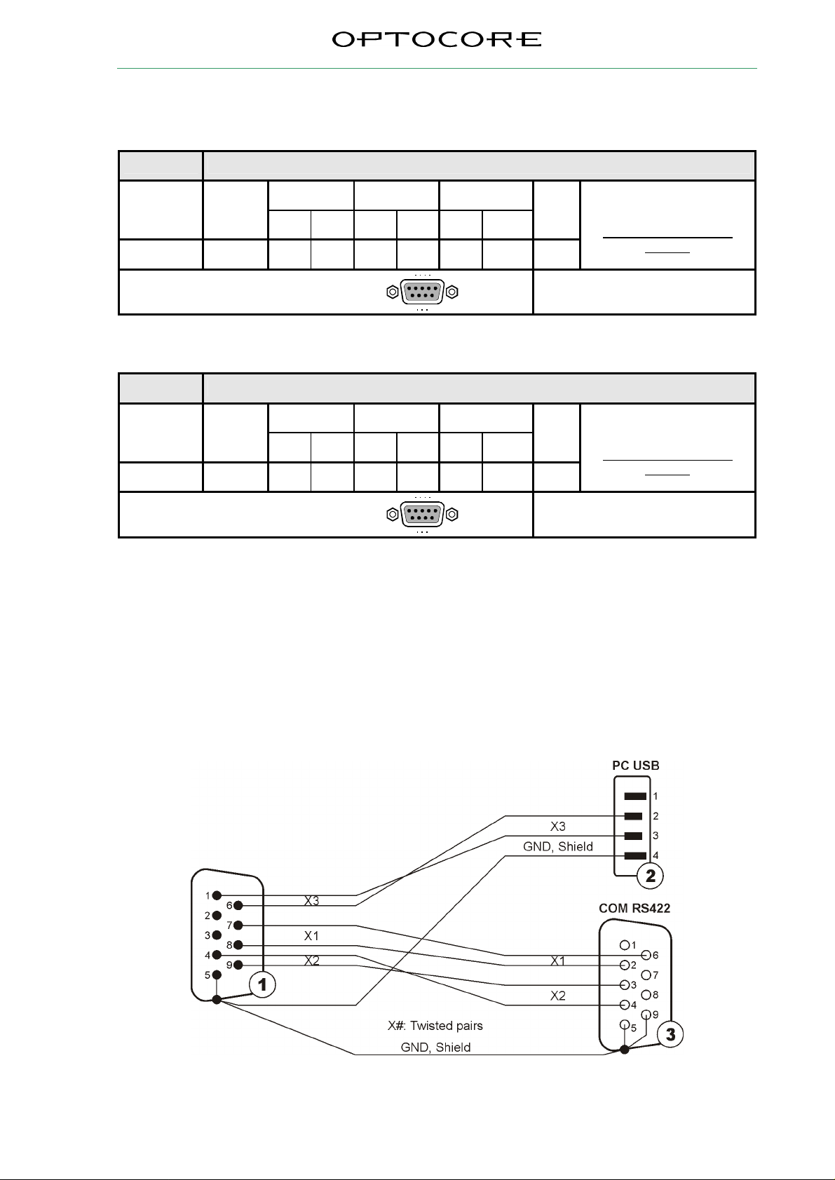
Connection Tables
YG2 Cards D-SUB9 Connector
Pin-out YG2 RS232/USB/RS422
Channel
GND
RXD TXD + - Port1 Port2
Pin 3 2 1 6 4, 9 7, 8 5
D-Sub-9- female
RS232 USB RS422
9 6
Use 1-modem cable, male –
female, to connect to PC.
Consider non-standard
pinning!
Locking system acc. to 4-40 UNC
YS2 Cards D-SUB9 Connector
Pin-out YS2 RS232
Channel
GND
RXD TXD
Pin 3 2 5
D-Sub-9- female
RS232
9 6
Use 1-modem cable, male –
female, to connect to PC.
Consider non-standard
pinning!
Locking system acc. to 4-40 UNC
TRI-Y Adapter
The TRI -Y cable combines the two RS422 and the USB-Port for PC connection in one D-Sub-9 connector. It is
used to establish the connection from the YG2-Card to a PC USB interface and remote interface of a console.
YG2 Auxiliary Port 2 x RS422 and USB port
D-Sub-9-male
Fastening system 4-40 UNC
X1...X2: RS422
X2...X3: USB
PC USB
Type A
X3: T/R x D
COM RS422
D-Sub-9-female
Fastening system 4-40 UNC
X1: R x D
X2: T x D
YG2 / YS2 15 / 15 Rev. 1.1
Page 16
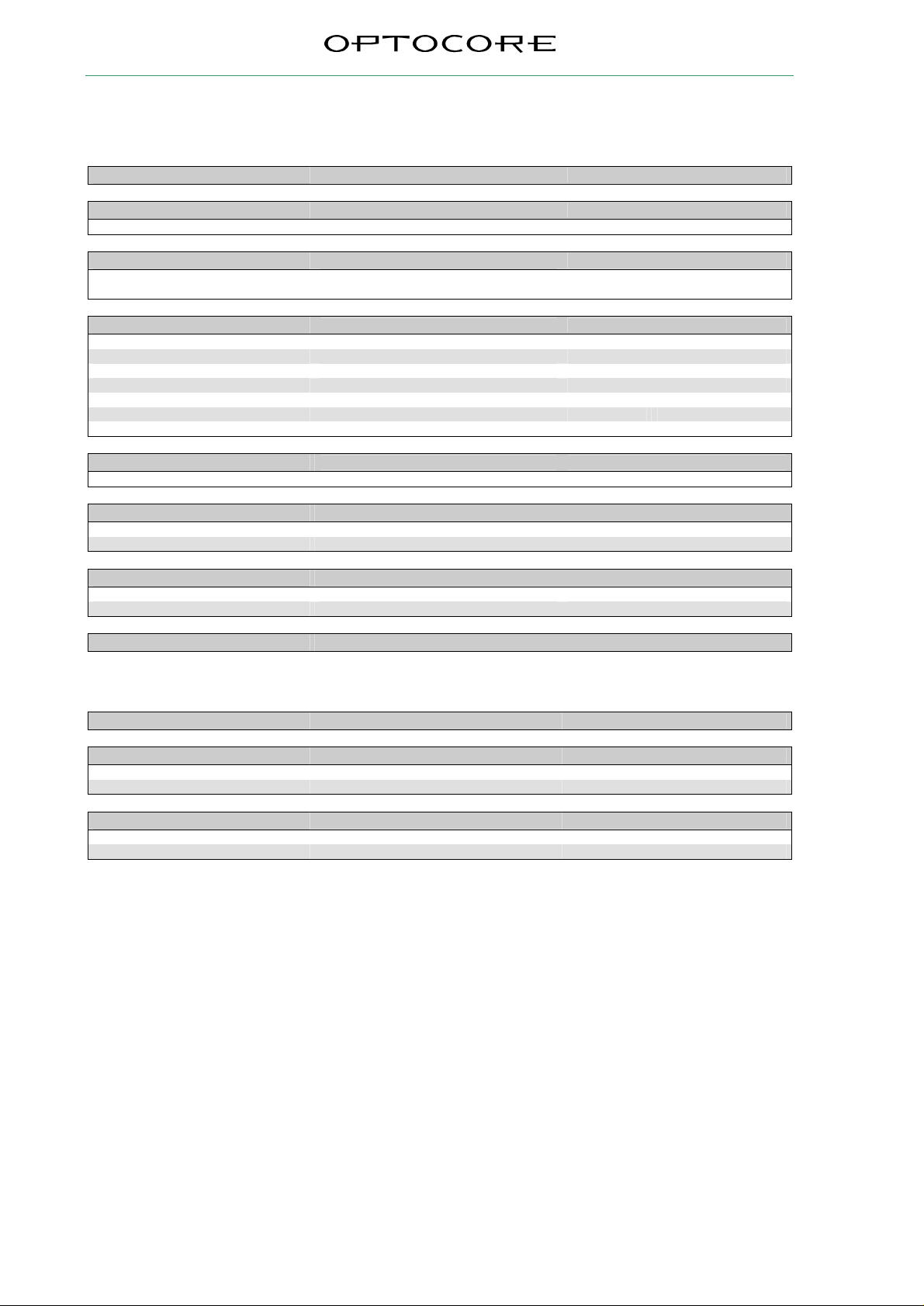
Technical Specifications
YG2 Card
Digital Audio (Mini - YGDAI Slot)
HA-Remote (Mini - YGDAI Slot)
Data channels Digital control data TX / RX up to 1Mbps
Word Clock (Mini - YGDAI Slot)
Data rate Dependant on used sample rate
Optical LINK
Connection Duplex LC 50 / 125
Digital Optical Network System Optocore
Transmission art Full duplex
Data rate 2 x 1Gbps
Length of optical waveguide cable Multimode fiber 50µm • 700m
Multimode fiber 62.5µm • 350m (not recommended)
Monomode fiber 9µm up to 70km (on request)
Auxiliary Ports
Data channels Digital control data 1 IN / 1 OUT up to 1Mbps
RS232 Port
Data channels Digital control data R x D, T x D
Data rate 57 600 Baud
SUB Port
Cable Type ANSI/TIA/EIA-568-A, TSB-95 CAT5
Max. Cable length 10 m / 33 feet
USB Port
YS2 Card
Digital Audio (Mini - YGDAI Slot)
SUB / MAIN Port
Cable Type ANSI/TIA/EIA-568-A, TSB-95 CAT5
Max. Cable length 10 m / 33 feet
RS232 Port
Data channels Digital control data R x D, T x D
Data rate 57 600 Baud
Convention Mini - YGDAI Interface
Convention Mini - YGDAI Interface
44.1 / 48 / 88.2 / 96kHz
+/-100ppm
Input, Output, Dual – Full bandwidth
Convention EIA / TIA - 422
Convention EIA / TIA - 232
Convention Optocore 64 channel CAT5
Remote control connection USB 1.1 full speed
Convention Mini - YGDAI Interface
Convention Optocore 64 channel CAT5
Convention EIA / TIA - 232
YG2 / YS2 16 / 16 Rev. 1.1
Page 17
Dimensions and Weight
Cards Dimensions
YG2 / YS2 Card
H x B x T: 100 x 160 x 40 [mm]
H x W x D: 3.94 x 6.3 x 1.57 [inch]
Cards Weight
YG2 Card
Weight: 365 g / 12.88 ounces
YS2 Card
Weight: 175 g / 6.17 ounces
Package Dimensions
YG2 / YS2 Card
H x B x T: 170 x 225 x 85 [mm]
H x W x D: 6.69 x 8.86 x 3.35 [inch]
Package Weight
YG2 Card
Weight: 540 g / 19.4 ounces
YS2 Card
Weight: 320 g / 11.3 ounces
Modifications, which serve the purpose of technical improvement of the cards, may be carried out
without prior notification.
YG2 / YS2 17 / 17 Rev. 1.1
Page 18
Warranty
Summary of Warranty
Optocore YG2 / YS2 cards is warranted against defects in material and workmanship for 24 months.
This warranty covers the original purchaser only and is not transferable. Valid evidence for warranty is the
official Optocore invoice issued by the distributor.
Optocore will, at its discretion, repair or replace a defective product, providing that the defect has appeared
under normal operating conditions.
This warranty does not cover damage from acts of God, accident, abuse, neglect, contamination, unauthorized
modification or misuse, operation outside of the environmental specifications for the product, improper site
preparation or maintenance, or abnormal conditions of handling. This would include over -voltage failures, and
conditions outside of the products specified ratings, problems with buyer-supplied software or interfacing, or
normal wear and tear of mechanical components. Optoc ore or its distributor will acknowledge the evaluation of
warranty after inspection.
Cards on which the Serial Number has been removed or defaced are not eligible for warranty service.
Failure to properly package and protection of the product during shipping may void this warranty.
How to Obtain Warranty Service
To return a defective product, please contact your dealer / distributor. Our web site: www.optocore.com provides
a complete list of Optocore dealers / distributors.
Always ensure the careful handling of the cards. If possible transport or shipping should always occur in special,
shock-absorbing transport cases. If these are not available we recommend well-upholstered packaging. We
strongly advise not to use simple flight-cases without rack-in-rack mounting.
Declaration of Liability
Optocore accepts no liability for damage caused to other devices through operation of the YG2 / YS2 cards.
Optocore is not liable for any damage caused by shipping accidents, misuse, abuse, operation with incorrect
voltage, operation with faulty peripheral equipment, or improper or careless installation of the cards.
Optocore accepts no claims for compensation whatsoever (e.g. cancellation of events).
Shipping Contents
YG2 Card
The standard shipment of an YG2 cards contains the following:
1 x YG2 Yamaha Mini - YGDAI card
1 x TRI-Y Cable
1 x Optical patch cable, length 2 m / 6.5ft, LC to SC type connectors, fiber 50µm (multi -mode)
1 x operating manual
YS2 Card
The standard shipment of an YS2 cards contains the following:
1 x YS2 Yamaha Mini - YGDAI card
1 x CAT5 Cable, length 0,25 m /0.82 ft
Any additionally purchased equipment such as optical waveguide cables in required lengths, D-Sub cables and
adapters, RS232-cables, and international electric cables have been supplied on your request and your
purchase order and cannot be listed in the above.
YG2 / YS2 18 / 18 Rev. 1.1
Page 19
Company Information
Mailing Address:
OPTOCORE GmbH
Lisbergstr. 7
D-81249 Munich
Germany
Telephone:
+49 – (0)89 – 8999640
Facsimile:
+49 – (0)89 – 89996455
Internet:
www.optocore.com
E-mail:
YG2 / YS2 19 / 19 Rev. 1.1
 Loading...