

Page 1
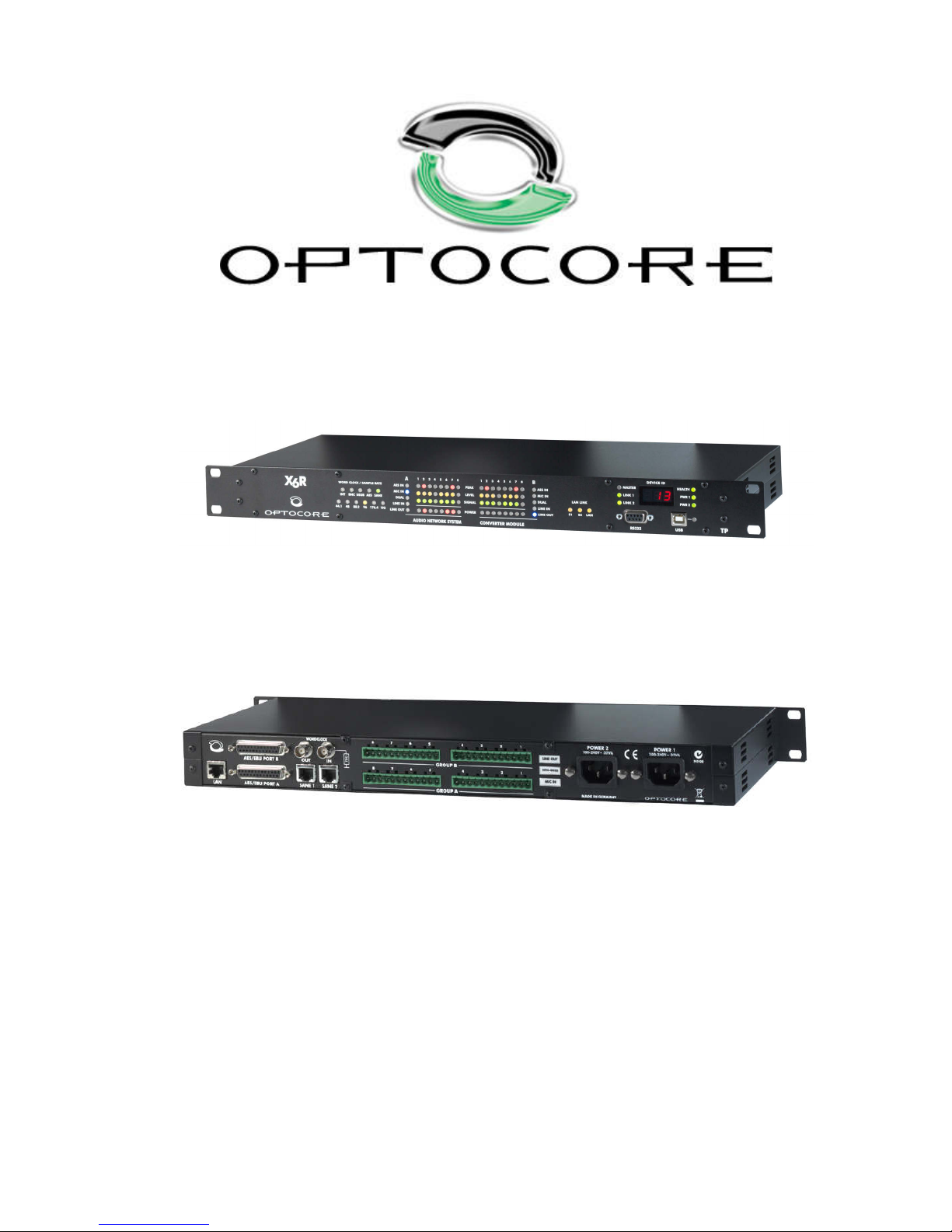
X6R/V3R-TP– A/D D/A Converter with SANE and Ethernet
Operating Manual
Rev. 2.4
Operating Manual for OPTOCORE X6R/V3R-TP Devices
A/D and D/A Converter with SANE and Ethernet
© Copyright 2015 All rights reserved
OPTOCORE GmbH
Lohenstr. 8
82166 Munich-Gräfelfing
Germany
Page 2

Page intentionally left blank
Page 3

X6R/V3R-TP
3 / 27
rev. 2.4
Important Safety Instructions
• Please read this manual carefully.
• Please keep this operating manual in a safe place.
• Heed all warnings.
• Follow all instructions.
• This device may only be used in accordance to the information provided in this operating
manual. Ensure that all recommendations detailed in this operating manual, especially the
safety recommendations, are followed before and during use of the device.
• Do not use this device near water and liquids, for example, in humid or damp rooms.
• Clean only with a dry cloth.
• Do not block or cover any ventilation openings. Install the device in accordance with the
operating manual.
• Do not install or place the device near a source of heat. Such as: radiators, power-amplifiers,
or any other heat emitting devices.
• Protect the power cord from being stepped on, crushed, pinched or damaged in any other way
or form. Pay special attention to the condition of the AC mains sockets on the device.
• Do not place this device on an unstable table, tripod, cart, etc. The device may fall, causing
serious damage to the device.
• The device can be disconnected from the power supply by unplugging the power cord. The
power cords must be freely accessible at all times. The device should be disconnected during
lightning storms or when the device is unused for a long period of time.
• The device must be grounded. Disconnecting the ground is strictly prohibited.
• The internal components of the switched-mode power supplies operate at very high voltages.
Coming into contact with the power supplies can lead to considerable electric shock, which
may result in death.
• Only use attachments and accessories that are specified by the manufacturer of the device.
• This device contains no user serviceable parts. Please consult with authorised service
personnel before attempting to carry out any repair or modification of the device.
• Your warranty will be voided if you tamper with the internal components of the device.
Page 4

X6R/V3R-TP
4 / 27
rev. 2.4
Purchaser Information
• Operating Manual
Please read this manual. If you call for technical support, we will assume that you have already done
so. Study the operating manual carefully in order to familiarise yourself with the device and its
operation. The operating manual contains important information on proper use of the device.
It cannot be guaranteed that this operating manual will not contain typographical mistakes or
misprints. The operating manual is regularly revised and updated.
Modifications, which serve the purpose of technical improvement of the device, may be carried out
without prior notification.
• Transport and Shipping
Always ensure careful handling of the device. The device should be transported and shipped in
shock-absorbing transport cases. If these are not available, we recommend well-padded packaging
such as the coated carton in which the device was delivered.
We strongly advise against the use of light weight flight-cases without shock-absorbing rack-in-rack
mounting.
• Environments
This device can be used in E1, E2, E3, E4, or E5 environments (as listed below) according to the
harmonised European standards EN55103-1 and EN55103-2 “Electromagnetic compatibility –
Product family standard for audio, video and audio-visual and entertainment lighting control apparatus
for professional use”
E1-Residental
E2-Commercial and light industrial
E3-Urban outdoors
E4-Controlled EMC environment e.g. broadcast and TV-studio
E5-Heavy industry
The product is intended for the use in moderate climate.
• Ventilation
Do not block or cover any ventilation openings. Install the device in accordance with the operating
manual. Allow for sufficient space around the units (at least 200 mm ≡ 7,87" free space behind the
rear-panel of the device) and make sure to allow for air circulation near the ventilation openings on
both sides of the device. Keep the rear of the rack open during operation. Do not operate the device
close to heat emitting equipment, such as power-amplifiers. Leave sufficient space (minimum ½ RU)
between the device and any heat emitting devices housed in the same rack.
An X6R/V3R device may be placed on top or beneath other Optocore products, except DD32E,
without additional space.
• Water and Moisture etc.
To prevent fire or shock hazard, do not expose the device to direct sunlight, dust, water, or rain during
operation or storage.
Please note:
Do not populate more than 4 adjacent rack spaces with Optocore devices.
Maintain 1RU of empty space between each 4 RU of Optocore devices.
Keep the equipment rack open during operation.
Ensure air circulation around the devices.
Maintain at least 200mm (~8”) clearance behind the rear panel of the devices.
Page 5
X6R/V3R-TP
5 / 27
rev. 2.4
• Cleaning
Only use a dry linen cloth to clean the device. If the unit is very dirty, moisten a cloth using a little
water and a small amount of household detergent. Never use cleansing agents containing solvents to
clean the device.
• Operating and Storage Temperature
Operating temperature: -20
°
C …50°C ≡ -4°F … 122°F; ensure proper ventilation
Storage temperature: -20°C …60°C ≡ -4°F … 140°F
• Power Supply
The device can be disconnected from the power supply by unplugging the power cord. The power
cords must be freely accessible at all times. The device should be disconnected during lightning
storms or when the device is unused for a long period of time
Never disconnect the main plug by pulling the cable, always pull the plug itself.
Power-supply cords should be routed in such a way that they are not likely to be walked on, crushed,
pinched, or damaged in any other way. Pay special attention to the plugs and the sockets of the
device.
• Fuse
There is no fuse in the device. The power supplies contain circuitry that protects the device from
overload.
• Lightning
For additional protection of this device during lightning storms, or when it is left unattended and
unused for a long period of time, disconnect the power cord. This will prevent damage to the device
due to lightning and power line surges. Disconnection from the mains power supply is only possible
by disconnecting the power plug from the mains socket.
• External objects and/or liquids
Never push objects of any kind into the device through openings in the casing. They may come into
contact with dangerous voltage points or short out parts that could result in a fire or electric shock.
Never spill liquid of any kind on the device.
Important:
The switched-mode power supplies operate at very high voltages.
Coming into contact with the power supplies can lead to considerable electric shock,
which may result in death.
Important:
A damaged power cable must be replaced immediately.
The device must be grounded. Disconnecting the ground is strictly prohibited. Ensure
that the device is always grounded using the power connector.
Do not cover the ground connection of the power connector with any kind of insulation
material!
Page 6

X6R/V3R-TP
6 / 27
rev. 2.4
• Cables and Accessories
Only use attachments that are specified by the manufacturer of the device.
Use high quality, properly terminated, cables to connect the device. The device should only be used
with optical fibre cables that are specified for use with the devices optical transceivers and within the
specified power budget of the optical transceivers. When not in use, ensure that the optical
connectors on the device and the optical fibre cables are covered with the provided caps.
Do not place this device on an unstable table, tripod, cart, etc. The device may fall, which can cause
injury and serious damage to the device. Any mounting of the device should follow the
manufacturer’s instructions, and should use mounting accessories recommended by the
manufacturer of the device.
• Servicing
Do not attempt to service this device yourself.
The device contains no user serviceable parts, components or controls. The operation of an opened
device is not permitted. Such operation can lead to damage of the device’s components due to lack
of air flow through the device.
The device may not be serviced, altered or modified without authorisation from Optocore or an
Optocore authorised distributor / dealer. Only qualified service personnel may carry out repair and
maintenance work on the device. The warranty of the device will be voided if any unauthorized
maintenance or repair work has been carried out.
Page 7
X6R/V3R-TP
7 / 27
rev. 2.4
CE/FCC-Conformity
This document confirms that the X6R/V3R-TP bearing the CE (Communauté Européenne) label meets all
requirements in the EMC directive 2004/108/EG laid down by the Member States Council for adjustment of legal
requirements. Furthermore the product complies with the rules and regulations of the low-voltage directive
2006/95/EG and the Restriction of Hazardous Substances Recast Directive 2011/65/EU (RoHS 2). This product
bearing the CE label complies with the following standards, ratified by CENELEC (Comité Européen de
Normalisation Electrotechnique):
Electromagnetic compatibility – Product family standard for audio, video, audio-visual and
entertainment lighting control apparatus for professional use
EN 55103-1, Emission
EN 55103-2, Immunity
EN 60065, Safety requirements
FCC notice
This device complies with Part 15 of the FCC Rules. Operation is subject to the following two conditions:
(1) this device may not cause harmful interference, and
(2) this device must accept any interference received, including interference that may cause undesired operation.
NOTE: This equipment has been tested and found to comply with the limits for a Class A digital device, pursuant
to Part 15 of the FCC rules. These limits are designed to provide reasonable protection against harmful
interference when the equipment is operated in a commercial environment. This equipment generates, uses and
can radiate radio frequency energy and, if not installed and used in accordance with the instruction manual, may
cause harmful interference to radio communication. Operation of this equipment in a residential area is likely to
cause harmful interference, in which case you will be required to correct the interference at his own expense.
Changes or modifications not expressly approved by Optocore GmbH could void the user’s authority to operate
this equipment.
Industry Canada Compliance Statement
This Class[A] digital device complies with Canadian ICES-003.
Avis de conformité à la réglementation d'Industrie Canada
Cet appareil numérique de la class[A] est conforme à la norme NMB-003 du Canada
The authorised declaration and compatibility certification lies with the manufacturer and can be viewed on
request. Responsible as manufacturer is:
OPTOCORE GmbH, Lohenstr. 8, 82166 Munich-Gräfelfing, Germany
represented by Marc Brunke, Managing Director
N.B. The awarding of the CE label confirms the compliance with legal directives issued for the manufacturer and
marketing of electronic and electrical devices. As such the CE label is not a "seal of quality" but rather proof that
the device bearing the CE label conforms with the electromagnetic compatibility standards laid down in the above
named testing regulations.
Munich, 11.12.2013
Marc Brunke
Page 8

Page intentionally left blank
Page 9

X6R/V3R-TP
9 / 27
rev. 2.4
X6R/V3R-TP - A/D and D/A Converter for SANE
Table of Contents
Important Safety Instructions ................................................................................................................................... 3
Purchaser Information..............................................................................................................................................4
CE-Conformity .........................................................................................................................................................7
Device Description.................................................................................................................................................11
Card Types ............................................................................................................................................................12
Front Panel ............................................................................................................................................................13
X6R-TP.......................................................................................................................................................13
V3R-TP.......................................................................................................................................................13
Rear Panel.............................................................................................................................................................15
X6R-TP with Analogue Input- and Output Cards........................................................................................ 15
V3R-TP or X6R-TP with Dual Microphone..................................................................................................15
Device Details........................................................................................................................................................16
SANE Ports ................................................................................................................................................16
A/D and D/A Converter...............................................................................................................................16
Analog Inputs..............................................................................................................................................16
Analog Outputs...........................................................................................................................................16
AES Ports...................................................................................................................................................16
Word Clock.................................................................................................................................................16
Power Supply .............................................................................................................................................16
Control...................................................................................................................................................................17
X6R-TP with DD32R(E)..............................................................................................................................17
X6R/V3R-TP in SANE Network Applications..............................................................................................17
Third Party Control......................................................................................................................................17
SANE bandwidth allocation....................................................................................................................................18
Connectors and Cables .........................................................................................................................................19
SANE Ports ................................................................................................................................................19
AES Ports...................................................................................................................................................19
RS232-Connection ..................................................................................................................................... 19
Connector Hood Quality .............................................................................................................................19
USB-Connection.........................................................................................................................................19
LAN-Connection ......................................................................................................................................... 19
Word Clock-Connection..............................................................................................................................19
Mains-Connection.......................................................................................................................................19
Hardware Connection............................................................................................................................................ 20
Example 1...................................................................................................................................................20
Example 2...................................................................................................................................................21
Connection Tables.................................................................................................................................................22
BI-B Cable.................................................................................................................................................. 23
Technical Specifications ........................................................................................................................................24
Dimensions and Weight.........................................................................................................................................25
Page 10

X6R/V3R-TP
10 / 27
rev. 2.4
Warranty and Liability.............................................................................................................................................26
Shipping Contents..................................................................................................................................................27
Company Information.............................................................................................................................................27
Page 11

X6R/V3R-TP
11 / 27
rev. 2.4
Device Description
Congratulations on your purchase of an X6R/V3R-TP A/D and D/A Converter Device with SANE and Ethernet.
The X6R/V3R-TP series manual will quickly demonstrate the advantages of the device and help to ease your dayto-day workload in a professional audio-visual environment.
9 in 1 - the X6R/V3R-TP is a network converter unit for SANE with the highest degree of flexibility with regards to
the I/O configuration. Four different card types enable the complete customisation of the I/O cards. It enables the
conversion of analogue signals - 16 inputs, 16 outputs, 8 inputs and 8 outputs, dual microphone inputs with dual
independent adjustable gains. The X6R/V3R-TP is designed for sample rates up to 192 kHz. Six different
versions of X6R and tree V3R are available:
X6R-TP-16MI
⇒ 16 microphone inputs - two 8-channel mic/line input boards
V3R-TP-8MI
⇒ 8 microphone inputs - single 8-channel mic/line input board
X6R-TP-16LI
⇒ 16 line inputs - two 8-channel line input boards
V3R-TP-8LI
⇒ 8 line inputs - single 8-channel line input board
X6R-TP-16LO
⇒ 16 line outputs - two 8-channel line output boards
V3R-TP-8LO
⇒ 8 line outputs - single 8-channel line output board
X6R-TP-8MI/8LO
⇒ 8 microphone inputs and 8 line outputs - single 8-channel mic/line input board
and single 8-channel line output board
X6R-TP-8LI/8LO
⇒ 8 line inputs and 8 line outputs - single 8-channel line input board and single
8-channel line output board
X6R-TP-8DualMic
⇒ 8 microphone inputs with two independent preamps each- single 8-channel
dual-mic/line input board
The X6R/V3R-TP units can be used together to create SANE CAT5 Network (64 audio channels + Ethernet).
Audio channels and Ethernet can be exchanged between SANE and the OPTOCORE OPTICAL DIGITAL
NETWORK SYSTEM – X6R/V3R-TP device can be connected to any FX R-series Optocore unit. All parameters
on the converters can be controlled and monitored with the same software application as all other Optocore
devices: OPTOCORE CONTROL software. Every channel from TP device connected by SANE is available
throughout the complete OPTOCORE fiber network.
The X6R/V3R-TP is especially designed for rack mounted applications and permanent installation. All cards are
equipped with Euroblock / Phoenix connectors. These common installation interfaces provide a simple and costefficient connection with other audio equipment.
The X6R-TP with the dual microphone input card removes the problem where only one of the FOH or Monitor
engineers can have full gain control of a single microphone input channel. Every microphone input incorporates
two independent microphone preamps meaning both can be adjusted individually. Therefore, analogue split
boxes with two stage racks to give FOH and monitor engineers the freedom to adjust their mic preamps directly at
their own console can be a thing of the past.
The X6R/V3R-TP with analogue mic input, line input and line output cards allow customised I/O configuration per
device. Two/one card slots can be equipped with different cards, so six combinations with 16 inputs, 16 outputs or
8 inputs and 8 outputs can be assembled for the X6R according to the customer’s requirements.
The microphone inputs include a high quality microphone preamp, phantom power and selectable gains in 1 dB
steps from -4 dB to +66 dB at a maximum input level of 22 dBu. The line inputs are equipped with selectable
maximum channel levels of 27 dBu, 22 dBu, 18 dBu, 8 dBu and the line output with a selectable maximum
channel level of 22 dBu, 18 dBu, 12 dBu, 8 dBu. The high quality preamps, A/D- and D/A converters make the
X6R units ideal for the incorporation into audio systems even if no OPTOCORE network is present. They provide
a wide dynamic range with negligible distortion and extremely low noise.
What do the product names refer to?
V3 refers to the channel capacity of the device. Where V is the Roman 5: 5+3=8.
X6 refers to the channel capacity of the device. Where X is the Roman 10: 10+6=16.
R refers to the Optocore Revolution series hardware platform.
TP specifies that the device is equipped with SANE twisted pair connectivity.
Page 12

X6R/V3R-TP
12 / 27
rev. 2.4
When using the X6R/V3R-TP as a SANE Network device the two AES/EBU ports can be configured as inputs or
outputs in groups of four and the AES/EBU channels can be exchanged between SANE and the I/O cards.
Word Clock input and output connections enable the synchronisation of the units to an external source and are
used to pass the word clock from one unit to the next. For stand-alone applications, the devices are equipped with
an internal word clock generator.
Up to 8 TP devices can be used in one SANE CAT5 daisy chain to extend OPTOCORE FX fiber node with up to
64 audio inputs and 64 audio outputs and additional 100Mbit LAN ports. Microphone preamps on the TP device
can be controlled from any node in the fiber network as well as from the console running Emulation Mode.
X6R/V3R-TP units can be set to work as high quality standalone analog to AES/EBU converter – in this case
SANE connectivity is deactivated.
Up to four X6R/V3R-TP, which are set as standalone converters, can be connected to the four principle D-Sub
ports of one DD32R(E) enabling the exchange of 32 AES/EBU signals (64 channels) and control data. The ports
include two control data channels. The X6R/V3R-TP units can be operated and controlled via the OPTOCORE
network with OPTOCORE CONTROL software without the need for any external data cable. For control in standalone applications LAN, USB or RS232 ports on the front / rear panels can be used as well.
All Optocore devices are designed and built using the latest programmable microprocessors and FPGA (field
programmable gate array) logic circuitry. This allows the devices internal logic to be updated, in the field, ensuring
a continual state-of-the-art device.
Optocore devices, and complete networks, are configured and operated using the OPTOCORE CONTROL
software. The software provides access to all configuration parameters and controls needed to operate the
system, including: naming channels, setting gains and phantom power, routing as well as recall and capture of
partial or full system configurations. The software can be operated offline as well as online with level meters for all
channels on the network.
The LEDs on the front panel of the X6R/V3R-TP units allow an instant overview regarding the status of each
channel, indicating if audio is present on a channel, if a peak level is reached and the activation of the phantom
power per channel.
Card Types
Four types1 of cards with Euroblock / Phoenix connectors can be incorporated into the card slots
• 8 microphone inputs
• 8 line inputs
• 8 line outputs
• 8 microphone inputs with two independent preamps each
The X6R/V3R-TP is shipped preconfigured with I/O cards according to the order placed with Optocore.
1
The additional AES/EBU and AES-SRC cards for X6R-TP are available upon request. Please contact [email protected]
for details.
Page 13
X6R/V3R-TP
13 / 27
rev. 2.4
Front Panel
X6R-TP
V3R-TP
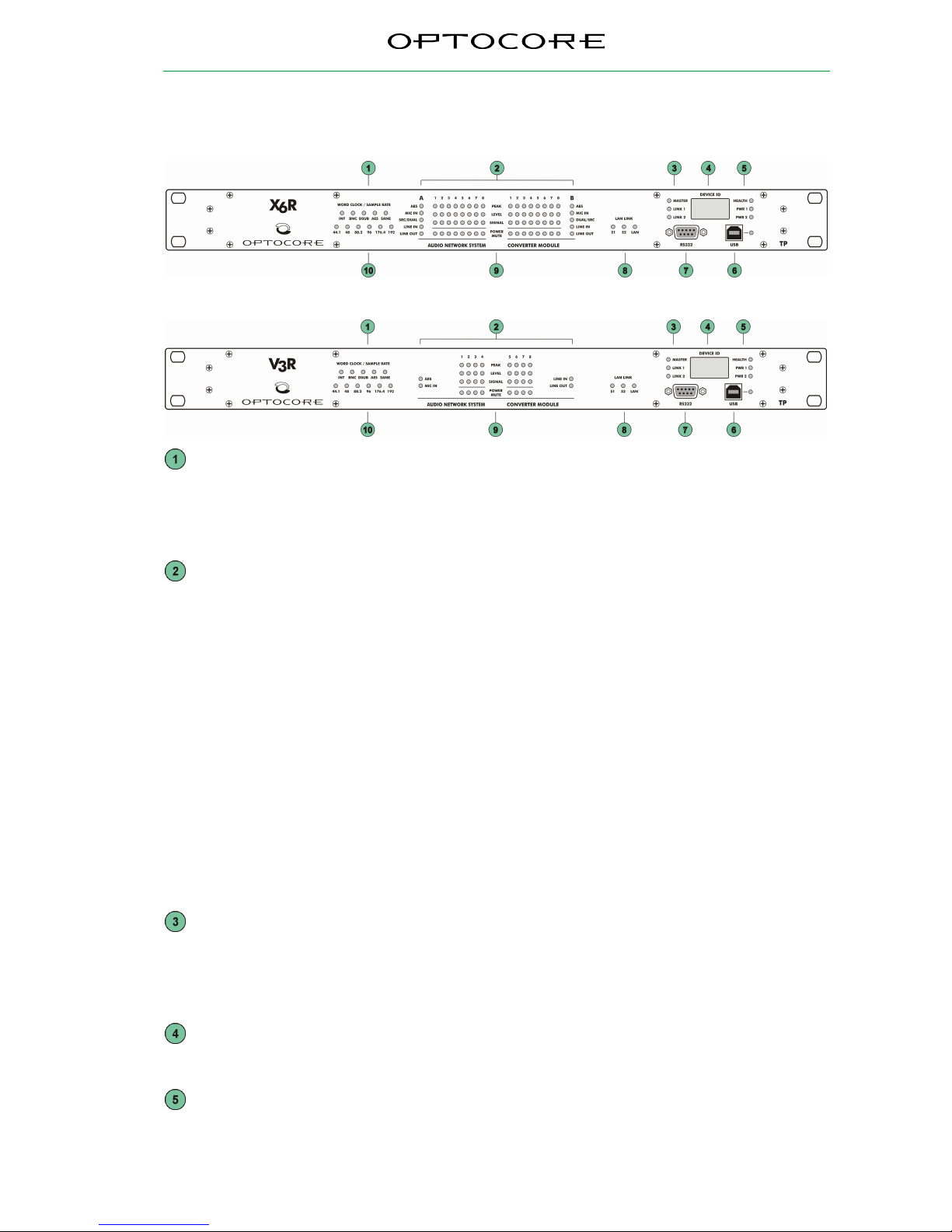
Word Clock LED: Indicates the selected word clock source:
INT: Internal word clock
BNC: External via BNC Input
DSUB: External via DSUB (available on request)
AES: External via AES (available on request)
SANE: External via SANE
Card and Signal Monitor for the 2 x 8 Channels (1 x 8 Channels for V3R)
A and B Card in slot A and B:
AES:
(only X6R, available on
request)
8 AES/EBU channels (16 audio) card
I/O switchable in groups of four
MIC IN:
8 channel microphone input card
SRC/DUAL:
(only X6R, available on
request)
8 AES/EBU inputs with sample rate converter/ 16 channel microphone input
card with 8 microphone inputs and two independent preamps each
LINE IN:
8 channel line input card
LINE OUT:
8 channel line output card
PEAK Red: Overflow, input level exceeds max. input level of 0dBFS
LEVEL Yellow: Warning level, input level exceeds -10dBFS
SIGNAL Green: Signal present ≥ -60dBFS, brightness controlled
Master LED: Indicates the master unit
LINK 1 LED: Communication is established via SANE 1 (rear panel)
LINK 2 LED: Communication is established via SANE 2 (rear panel)
Device ID Display: Indicates the identification number of the device
HEALTH LED: Green: Power supply is correctly working, temperature is below the limit
PWR 1 LED: Power supply 1 is working correctly
PWR 2 LED: Power supply 2 is working correctly
Page 14

X6R/V3R-TP
14 / 27
rev. 2.4
USB plug and LED: USB connection for remote control via PC
Green: Indicates data activity
RS232 plug: D-Sub-9 RS232 connection for remote control and update via PC
LAN LINK:
S1: Ethernet communication is established via SANE 1 (rear panel)
S2: Ethernet communication is established via SANE 2 (rear panel)
LAN: Ethernet communication is established via LAN (rear panel)
POWER / MUTE Mic Card Phantom Power / Output Card Mute
Sample rate LED: Yellow: 44.1 / 48 / 88.2 / 96 / 176.4 / 192 kHz
Page 15
X6R/V3R-TP
15 / 27
rev. 2.4
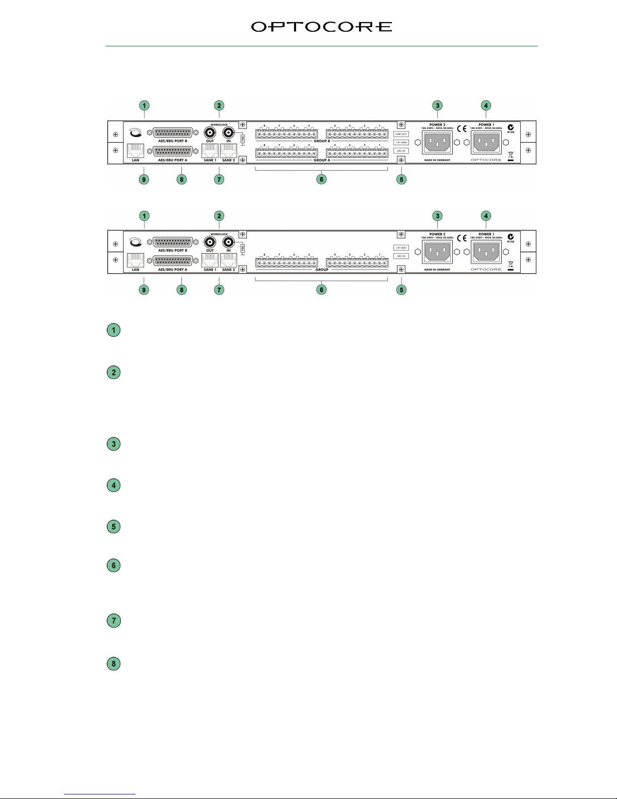
Rear Panel
X6R-TP with Analogue Input- and Output Cards
V3R-TP or X6R-TP with Dual Microphone
AES Port A and B: 2 x 8 AES data channels, plus two control data channels
Word Clock IN: BNC Word clock input allowing synchronization of SANE devices/network
from an external word clock source (available on request)
Word Clock OUT: BNC Word clock output for synchronization of external devices
POWER 2: Mains input for power supply 2 (100 … 240 V)
POWER 1: Mains input for power supply 1 (100 … 240 V)
Labels: I/O card type in the slot(s) and serial number
GROUP: Cards with Euroblock / Phoenix connectors (8 channels) in slot GROUP A and
GROUP B at a X6R-TP or in slot GROUP A only at a V3R-TP
SANE 1: SANE RJ-45 interface for data transmission + 100 Mbit Ethernet
SANE 2: SANE RJ-45 interface for data transmission + 100 Mbit Ethernet
LAN: 100 Mbit RJ-45 Ethernet interface
Page 16

X6R/V3R-TP
16 / 27
rev. 2.4
Device Details
SANE Ports
All TP units are equipped with two RJ45 200MBit SANE Ports for 64 bi-directional channels of synchronous audio
+ 100MBit Ethernet.
A/D and D/A Converter
24-bit converters supporting sample rates of 44.1, 48, 88.2, 96, 176.4, 192 kHz ensure the high-quality conversion
of analogue audio signals.
Analog Inputs
The microphone inputs include preamps with selectable gain between -4 dB to 66 dB in analogue 1 dB steps.
Phantom Power (+48V) can be activated individually on each input. The maximum input level is +22 dBu. It is
possible to use microphone inputs for line level sources.
The line inputs gain controls can be individually adjusted in four steps of maximum input level: 27 dBu, 22 dBu,
18 dBu and 8 dBu.
Analog Outputs
The outputs gain controls can be individually adjusted in four steps of maximum output level: 22 dBu, 18 dBu,
12 dBu and 8 dBu.
AES Ports
According to the AES/EBU standard, each physical channel contains two audio channels, i.e. with the eight digital
channels on one AES Port, 16 audio channels are available.
All X6R/V3R-TP units are equipped with two AES 8-channel Ports labelled A and B. The ports are software
adjustable for different tasks and can function as a digital split if required. Both ports can operate in parallel. In
converter mode the X6R/V3R-TP will automatically take its AES/EBU signals from the port with valid incoming
data with Port A having the highest priority and transmit the Preamp Control. Port B can be used to re-transmit the
incoming signals if required. Port B configuration depends on the hardware setup of the analogue I/O boards in
the device.
Word Clock
Devices with Optocore/SANE modules are equipped with an internal, high quality, low jitter clock generator as
well as Word Clock inputs and outputs. Any device on the network can act as the master of the network and pass
Word Clock to networked Optocore/SANE devices.
The internal/networked Word Clock is available at the Word Clock output connector of each device on the network
to synchronize non-networked devices.
In standalone network configurations external synchronization is not required.
The Word Clock input termination can be switched on using the OPTOCORE CONTROL software’s Local
Settings. External termination is not required to avoid cable reflections.
Word Clock master negotiation after any Word Clock source failure is done automatically.
Power Supply
The device is optionally equipped with two power inputs and power supply units. If one power supply fails, due to
malfunction of the feeding power line or the power supply unit itself, the device will automatically switch over to
the other power supply unit. In order to make the power supply redundant, both power inputs must be connected
to the mains supply, if possible to different phases, power supply systems, or even better, one of them to an
uninterrupted power supply (UPS).
The power supply units operate with mains voltage of 100 ... 240 V and frequency of 50 … 60 Hz. Thus the
device can be used throughout the world without any modifications or transformers.
Important:
The switched-mode power supplies operate at very high voltages.
Coming into contact with the power supplies can lead to considerable electric shock,
which may result in death.
To prevent electric shock, do not remove any covers of the device.
Page 17
X6R/V3R-TP
17 / 27
rev. 2.4
Control
All system and device parameters are set using OPTOCORE CONTROL software on a PC. If the X6R/V3R-TP
units are connected to a FX Device using SANE or DD32R(E) using the BI-B as shown in Connection Tables the
control and audio data is transmitted over SANE resp. the D-Sub-25 interfaces. OPTOCORE CONTROL can
control all X6R/V3R units in a network. In stand-alone applications, the RS232, LAN or USB port enables the
configuration and monitoring of one unit attached directly to the PC.
X6R-TP with DD32R(E)
X6R-TP devices can work in converter mode and can be fully controlled through the Optocore network when
connected to DD32R-FX or DD32E device. The control of the microphone preamps, levels etc. is enabled by
choosing an X6R with the appropriate card configuration in the local settings dialog of the DD32R(E) under Port
setup. Up to four X6R and eight V3R units can be connected to one DD32E using BI-B, Tri-A or Tri-B cables. The
I/O configuration of each DD32R(E) port depends on the card configuration of the attached X6R device:
Cards Device I/O
2 x MIC IN
X6R-16MicIn 16 In
2 x LINE IN
X6R-16LineIn 16 In
2 x LINE OUT
X6R-16LineOut 16 Out
1 x MIC IN and 1 x
LINE IN
X6R-8MicIn/8LineIn 16 In
1 x MIC IN and 1 x
LINEOUT
X6R-8MicIn/8LineOut 8/8 Reverse
1 x LINE IN and 1 x
LINEOUT
X6R-8LineIn/8LineOut 8/8 Reverse
1 x DUAL MIC
X6R-8DualMic 16 In
If 8/8 reverse is chosen, physical channels 1-4 (audio channels 1-8) of the D-Sub-25 ports on the DD32R(E) are
outputs, physical channels 5-8 (audio channels 9-16) are inputs. The X6R AES ports are configured as eight
inputs first followed by eight outputs. Therefore by using the straight-through BI-B cable and choosing 8/8
Reverse the inputs and outputs of the DD32R(E) and X6R are connected correctly.
X6R/V3R-TP in SANE Network Applications
X6R/V3R-TP devices can be connected in a SANE daisy chain and integrated with the Optocore network through
any R-series FX device. All device parameters like gain, phantom and pad can be accessed and modified using
OPTOCORE CONTROL software, which runs on PC connected via USB or RS232 to any FX device or via LAN
to any LAN or SANE port.
Third Party Control
Third party protocols for device controlling can be used. It is possible to control Optocore preamps directly from
Yamaha, Studer/Soundcraft, SSL, Lawo and Digico consoles with Special Emulation Mode configured. A Multiple
Emulation Mode feature enables to control preamps in Optocore network from four different consoles.
Please note:
Please refer to the Optocore Quick Start Guide for the basic system configuration and
setup.
For more detailed setup please refer to the Optocore Software Manual
Page 18

X6R/V3R-TP
18 / 27
rev. 2.4
SANE bandwidth allocation
The standard bandwidth allocation of a SANE link is as follows:
Audio 64 Channels @ 48 KHz
Ethernet 100 MBit Fast Ethernet
Page 19

X6R/V3R-TP
19 / 27
rev. 2.4
Connectors and Cables
SANE Ports
Use standard, fully wired, twisted pair cable (Cat 5, Cat 5e, Cat 6) terminated with RJ-45 connectors. SANE
utilizes all four pairs of the Cat 5 cable, two pairs for standard Ethernet transmission and two pairs for the SANE
synchronous audio transport. A SANE cable shall not exceed a total cable distance of 100 m
AES Ports
According to the RS422/RS485 hardware standard used for the transport of AES/EBU standards, each channel
requires a twisted pair. A common braided shield should enclose the pairs.
Standard computer data cables are sufficient for good quality AES data transmissions over the short distances
typically necessary in most applications.
RS232-Connection
Use a standard shielded RS232 cable.
Connector Hood Quality
Locking screws for D-Sub connectors should be compatible with 4-40 UNC. Care should be taken in selecting the
right type of connector hoods in order to fulfil the requirements of EMI-radiation directives. Full metal connector
hoods should be used, approved acc. to VDE 0871, FCC 20780 and EMC directive 2004/108/EG, providing
attenuation > 40 dB between 30 MHz up to 1 GHz. The shield of the cable should have contact to the connector
hood.
USB-Connection
Use a USB-A to USB-B cable between the PC and the Optocore device.
LAN-Connection
Use a standard twisted pair cable (Cat-5, Cat-6) with RJ-45 connectors.
Word Clock-Connection
Use 75 Ω-coaxial-cable with BNC-connectors.
Mains-Connection
Standard power cords with IEC C13 connectors.
Page 20
X6R/V3R-TP
20 / 27
rev. 2.4
Hardware Connection
Example 1
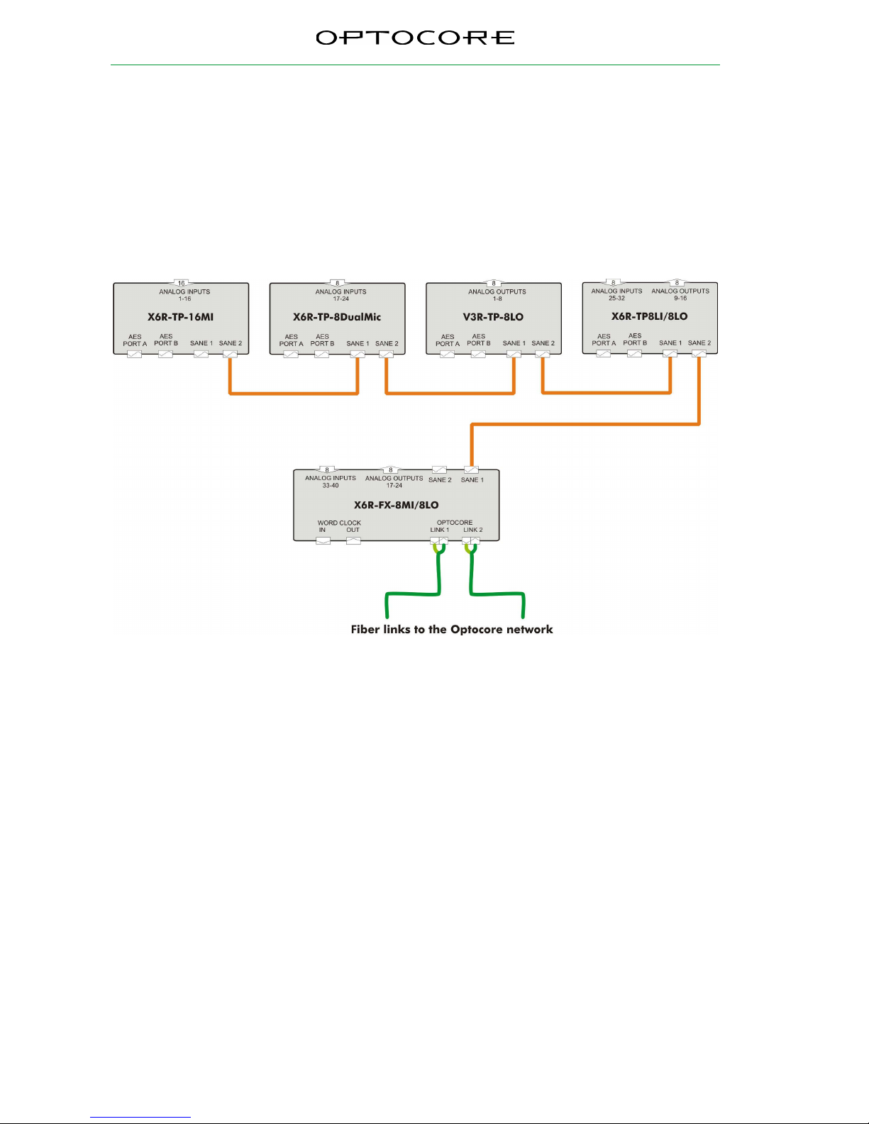
The X6R/V3R-TP can be used as a SANE to Optocore converter. The X6R/V3R-FX with analog I/O cards is
connected with three X6R-TPs with different types of cards and one V3R-TP by CAT5 cables. The word clock is
transmitted by SANE and Optocore, so there is no need to use additional 75 Ω cables. The following figure
demonstrates the configuration of a 32 inputs and 16 returns SANE system, which can be combined with a bigger
Optocore ring. In this example there are three Optocore X6R-TP units: one with two mic input cards, second one
works as a dual mic device, third X6R-TP with one input and one output analogue card. There is also one V3R-TP
with one output card. All those devices are creating a CAT5 SANE network. The X6R-FX device is used as a
bridge between SANE and Optocore network.
Fig. 1: Connection of three X6R-TP units, one V3R-TP and one X6R-FX.
Each of the devices in this example is an analogue converter with SANE network interface. It is possible to use
AES ports, which are built in each TP device to input or output additional digital audio channels to/from the
network. The configuration of the AES ports as inputs and/or outputs and the routing is carried out with
OPTOCORE CONTROL. It is possible to route input channels from other devices in an Optocore ring to the –TP
outputs.
The same single CAT5 connection transports audio data, word clock and 100 Mbit Ethernet.
Page 21
X6R/V3R-TP
21 / 27
rev. 2.4
Example 2
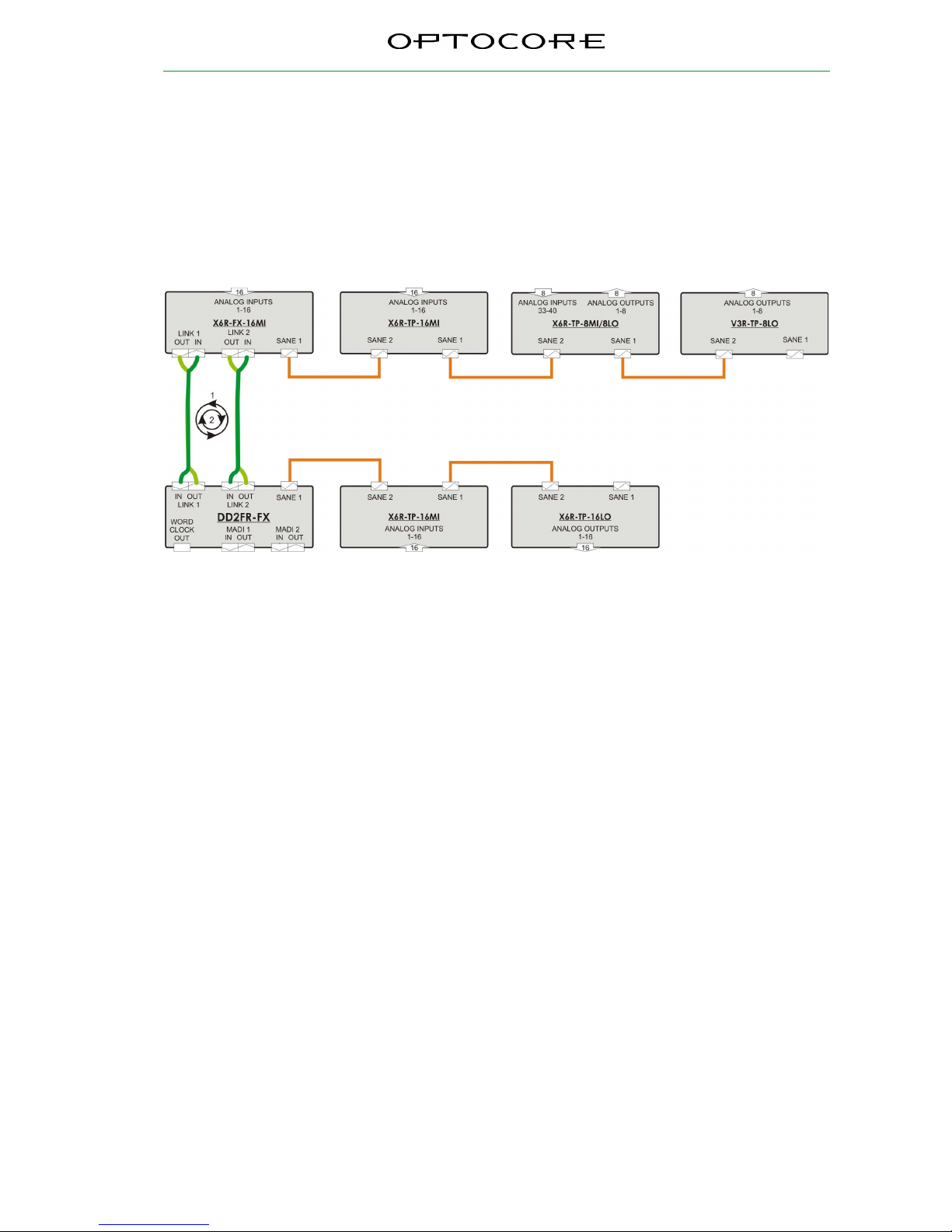
X6R/V3R-TP devices are used mostly as a channel extension to main fibre optic Optocore network nodes. In this
example two FX devices are connected with dual ring redundant network. X6R/V3R-TP devices are used as an
analogue extension. On the one end three TP devices extend the channel count of X6R-FX unit. This group of
devices can be used as a stage box with 40 microphone inputs and 16 line outputs. Furthermore distance
between each device can be 100m, so each device can be located in a different place of the stage. On the other
end of the fiber loop DD2FR-FX, with two MADI ports, is extended by two TP devices. MADI ports can be
connected to 3rd party consoles. With OPTOCORE CONTROL software Emulation Mode can be set therefore
consoles may control gains for all OPTOCORE mic preamps directly without additional control unit.
Fig. 2: Connection of four X6R-TP units, one V3R-TP, one X6R-FX and one DD2FR-FX.
Optocore network shown above is also capable to transport 100Mbit Ethernet without any additional equipment as
well as control data e.g. RS485/RS422. Each X6R/V3R-TP device is equipped with two AES/EBU ports which can
be used as a additional digital I/O. All setup, routing, configuration should be performed with OPTOCORE
CONTROL software.
OPTOCORE network in this configuration example requires no additional cabling for WORD CLOCK. Sync
signals are transported simultaneously with OPTOCORE/SANE signal.
Page 22
X6R/V3R-TP
22 / 27
rev. 2.4
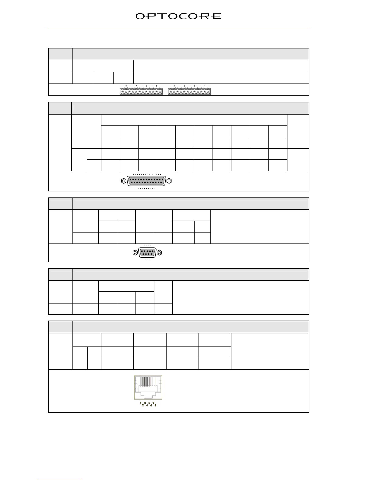
Connection Tables
Pin-out Balanced Mic/Line Inputs, Line Outputs
Each Channel
+ - GND
Euroblock
Pin-out
AES Ports A + B
RS422 In or Output Control
Channel
1 2 3 4 5 6 7 8 9 10
AES-Data 1+2 3+4 5+6 7+8 9+10 11+12 13+14 15+16
GND
+ 1 2 3 4 5 6 7 8 11 24
Pin
- 14 15 16 17 18 19 20 21 9 22
10, 12,
13, 23,
25
D-Sub-25- female
13
1
25
14
Locking system acc. to 4-40 UNC
Pin-out RS232-Port
RS232 Power
Channel
RXD TXD
Internally
bridged
+5VS GND
Pin 3 2 1, 4, 6 7, 8 9 5
Use standard RS232 cable, male –
female, to connect to PC
D-Sub-9- female
5
1
9
6
Locking system acc. to 4-40 UNC
Pin-out USB-Port
USB
Channel
VBUS D - D +
GND
Pin 1 2 3 4
USB device-connector
Pin-out SANE – Synchronous Audio and Ethernet
SANE /
“MADI” In
SANE /
“MADI” Out
Ethernet
In
Ethernet
Out
+ 7 4 3 1
Pin
- 8 5 6 2
A device compatible with
10/100MB Fast Ethernet can be
connected to a SANE port for
Ethernet data communication.
RJ-45
Page 23
X6R/V3R-TP
23 / 27
rev. 2.4
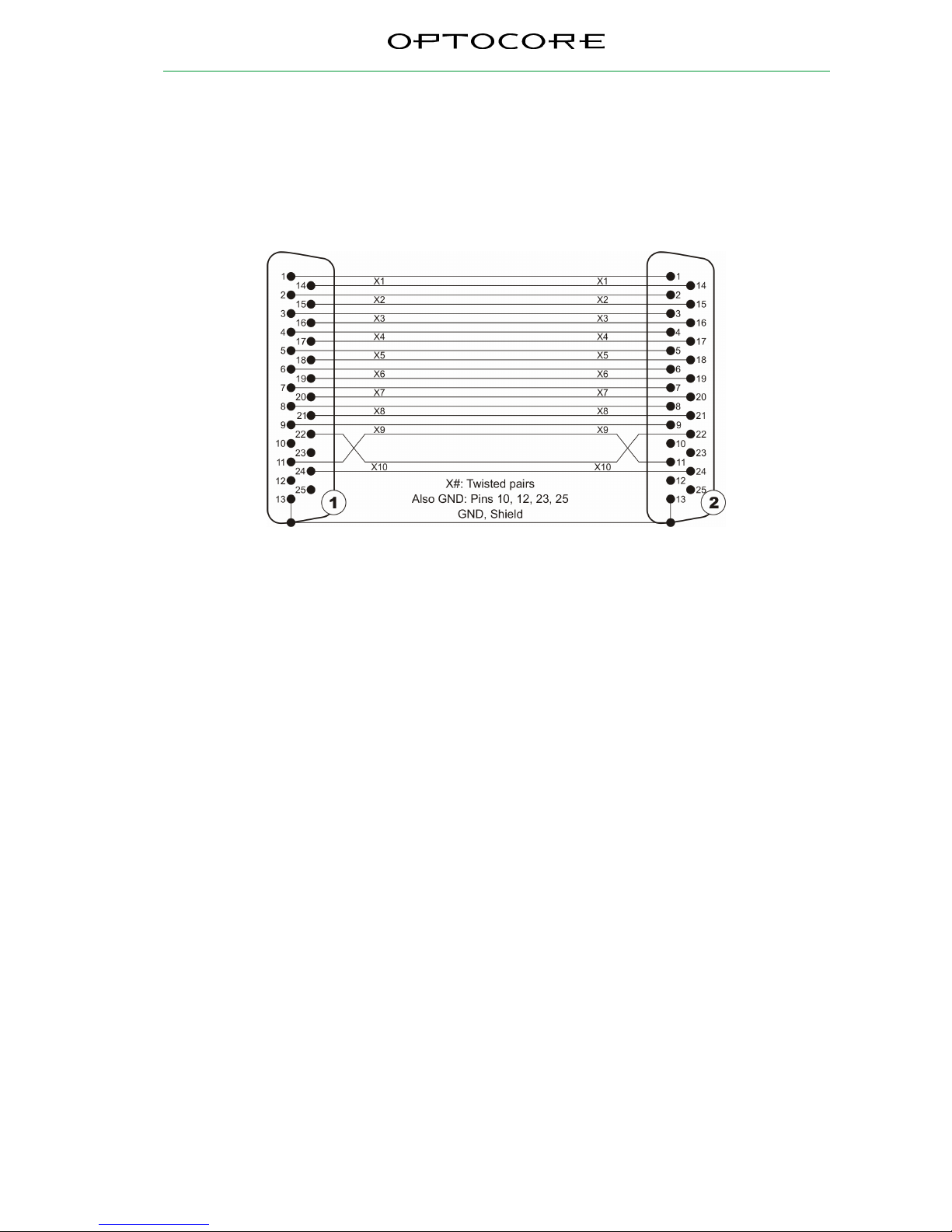
BI-B Cable
In order to connect a principal port of a DD32R(E) to an AES port of an X6R converter device, a BI-B cable with
D-Sub-25 connectors should be used.
DD32R(E) Principal Port
X1…X8: 8 AES/EBU channels
X9, X10: Control channels
D-Sub-25-male
Fastening system: 4-40 UNC
X6R/V3R AES Port A
X1…X8: 8 AES/EBU channels
X9, X10: Control channels
D-Sub-25-male
Fastening system: 4-40 UNC
Page 24
X6R/V3R-TP
24 / 27
rev. 2.4
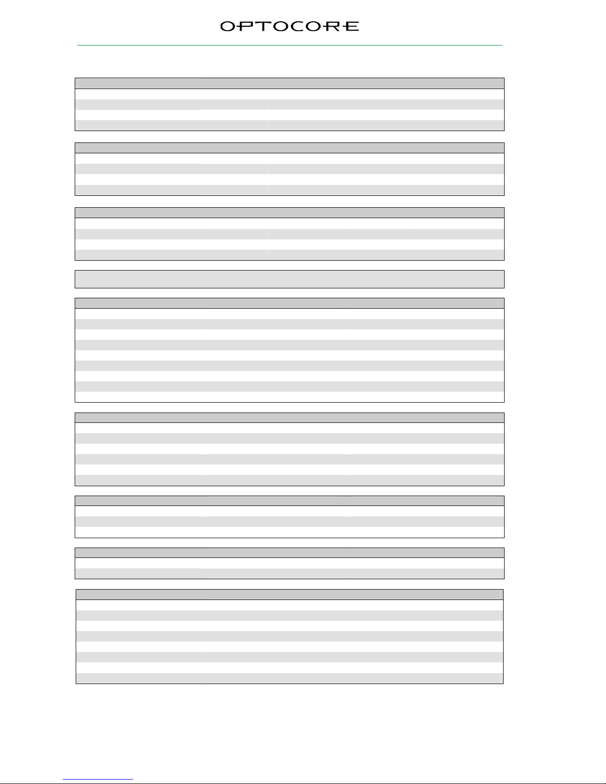
Technical Specifications
Analog Audio Mic Inputs
ADC
Impedance, Gain / steps Single and Dual 4.5kΩ -4 dB to +66 dB 1 dB steps
Maximum input level @ -4 dB Gain +22 dBu @ +66 dB Gain -48 dBu
SNR @ -4 dB Gain 122.5 dB(A) @ +66 dB Gain 81.5 dB(A)
THD+N @ -1dBFS @ -4 dB Gain ≤ -102 dB @ +40 dB Gain ≤ -100 dB
Analog Audio Line Inputs
ADC
Impedance, Gain / steps 10kΩ -9, -4, 0, +10 dB 4 steps
Maximum input level @ -9 dB Gain +27 dBu @ +10 dB Gain +8 dBu
SNR @ -9 dB Gain 127.5 dB(A) @ +10 dB Gain 108 dB(A)
THD+N @ -1dBFS @ -9 dB Gain ≤ -102 dB @ +10 dB Gain ≤ -102 dB
Analog Audio Line Outputs
DAC
Impedance, Gain / steps 22Ω +4, 0, -6, -10 dB 4 steps
Maximum output level @ +4 dB Gain +22 dBu @ -10 dB Gain +8 dBu
SNR @ +4 dB Gain 123 dB(A) @ -10 dB Gain 108 dB(A)
THD+N @ 0dBFS @ +4 dB Gain ≤ -100 dB @ -10 dB Gain ≤ -103 dB
Conditions
Reference 0dBFS ≡ 18dBu, Input / Output Termination 150R / 300R, Sample Rate
48kHz. Specs noticed as typical, if not otherwise stated
AES Ports
Convention EIA / TIA - 422
Channels
AES/EBU 2 x 8
Audio channels 2 x 16
Data rate
Depending on selected sample rate Up to 30 Mbit/s per channel
Impedance
Termination
120 Ω-switchable / ≥ 96 kΩ
Source ≤ 10 Ω, Multi-drop feature
Drive level
Output ≥ 2 V
pp
Zero level
Referring to GND + 1.7 V
Sense level
Input ≥ 400 mV
pp
CM-voltage at bus terminals
Referring to GND - 7 V … + 12 V
Word clock
Hardware standard BNC - 75 Ω
Data rate
Depending on selected sample rate Up to 192 kHz
Impedance
Output ≤ 5 Ω
Input 75 Ω
Drive level
Output ≥ 1 V
pp
Zero level
Referring to GND + 1.7 V
Sense level
Input ≥ 400 mV
pp
Remote Control
Convention
RS232
EIA / TIA - 232 57 600 Baud
USB
USB 2.0 - Device 12 Mbit/s
LAN
IEEE - 802.3 10/100 Mbit/s
SANE, LAN
Convention
Audio TIA - 568A/B, Optocore 200 Mbit/s
LAN TIA - 568A/B, IEEE - 802.3 10/100 Mbit/s
Power supply
Type
Switch-mode, universal input
Mains voltage
100 … 240 V
Frequency
50 … 60 Hz
Power consumption
Depending on device, 32VA - Max
Security classification
Class 1: basic insulation, connected to the protective grounding conductor
Security regulations
Harmonised European standard EN60065
Mains connector
acc. to IEC-950
Cooling
Passive, via surface and ventilation-slits on both sides
Page 25
X6R/V3R-TP
25 / 27
rev. 2.4
Dimensions and Weight
Front panel: width 483 mm / 19 inch
height 44 mm / 1.73 inch
depth 200 mm / 7.87 inch
Rear panel: width 438 mm / 17.25 inch
Weight
2.7 kg ≡ 4.41 lbs
Please note:
Modifications that serve the purpose of technical improvement may be carried out
without prior notification.
Page 26

X6R/V3R-TP
26 / 27
rev. 2.4
Warranty and Liability
Summary of Warranty
OPTOCORE X6R/V3R-TP device is warranted against defects in material and workmanship for 60 months (5
years) from the date of purchase. This warranty does not include mechanical damages caused by misuse. This
warranty covers the original registered purchaser only and is not transferable. This warranty does not apply to
devices which have been purchased in used condition or demonstrator equipment.
OPTOCORE will, at its discretion, repair or replace a defective product, providing that the defect has occurred
under normal operating conditions.
This warranty does not cover damage from acts of God, accident, abuse, neglect, contamination, unauthorised
modification, misuse, or operation outside of the environmental specifications for the product, improper site
preparation or maintenance, or abnormal conditions of handling. This would include over-voltage failures, and
conditions outside of the products specified ratings, problems with customer-supplied software or interfacing, or
normal wear and tear of mechanical components. OPTOCORE will acknowledge the evaluation of warranty after
inspection.
Not covered by this warranty are defects arising from electromagnetic or electrical interferences, deficiency,
excess, or surge of electrical supply, air conditioning, or humidity. This also includes repairs made necessary by
dirt, abrasion, moisture, rust, corrosion, or similar conditions.
Devices on which the Serial Number has been removed or defaced are not eligible for warranty service.
OPTOCORE devices contain no user-serviceable components: refer to qualified service personnel for repair or
upgrade. The warranty will be void if you tamper with internal components. Please address any questions or
inquiries to OPTOCORE or your distributor/dealer.
For a full warranty conditions refer to the Warranty Card attached to every Optocore device with a first shipment.
How to Obtain Warranty Service
When discovering a problem with an OPTOCORE device, you should contact either Optocore directly or a
dealer/distributor to determine and confirm a hardware fault. If it is a software issue the hardware must not be
returned to OPTOCORE, OPTOCORE will issue a support ticket in this case.
If hardware service is required within the warranty period, take the equipment, along with warranty card, to the
nearest authorised OPTOCORE dealer/distributor. The dealer/distributor will make sure that the device is
serviced according to the terms of warranty by OPTOCORE or an authorised service centre.
If the equipment needs to be returned directly to OPTOCORE, first contact [email protected].
OPTOCORE requires the serial number of the equipment intended for return, as well as a short description of the
problem. If possible, you should also provide us a phone number where you can be reached during regular
working hours. To return a defective product, please contact your distributor / dealer. Our web site:
http://www.optocore.com/ provides a complete list of Optocore distributors / dealers.
Make sure the equipment being returned is packed carefully to protect it from damage during shipment.
OPTOCORE requires that shipments are pre-paid and insured – unless specifically authorized in advance.
We strongly advise not to use simple flight-cases without rack-in-rack mounting.
Declaration of Liability
Optocore accepts no liability for damage caused to other devices through operation of the X6R/V3R-TP device.
Optocore is not liable for any damage caused by shipping accidents, misuse, abuse, operation with incorrect AC
voltage, operation with faulty peripheral equipment, or improper or careless installation of the device.
Neither OPTOCORE nor anyone involved in the production of the equipment shall be liable for
any indirect, special, disciplinary, consequential, or incidental damages arising out of the use
or inability to use this equipment even if OPTOCORE has been advised of the possibility of
such damages. In no event shall the liability of OPTOCORE exceed the purchase price of any
defective equipment.
Optocore accepts no claims for compensation whatsoever (e.g. cancellation of events).
Page 27

X6R/V3R-TP
27 / 27
rev. 2.4
Shipping Contents
The standard shipment of a X6R/V3R-TP unit contains the following:
• 1 X6R/V3R-TP unit
• 1 CAT5 patch cable
• 2 power cables (according to the number of PSU units installed)
Any additionally purchased equipment such as optical wave-guide cables in required lengths, D-Sub cables and
adapters, RS232 cables, and international electric cables, which have been supplied on your request and your
purchase order, cannot be listed above.
Please note that due to the Ecology reason standard shipment does not contain printed copy of User Manual. All
latest OPTOCORE user manuals can be downloaded from the website:
http://www.optocore.com/index.php/support/downloads
Printed version of User Manual is available on a special demand. Please contact [email protected]
if printed version is required.
Company Information
Mailing Address:
OPTOCORE GmbH
Lohenstr. 78
D-82166 Munich-Gräfelfing
Germany
Telephone:
+49 – (0)89 – 8999640
Facsimile:
+49 – (0)89 – 89996455
Internet:
www.optocore.com
Email:
 Loading...