

Page 1
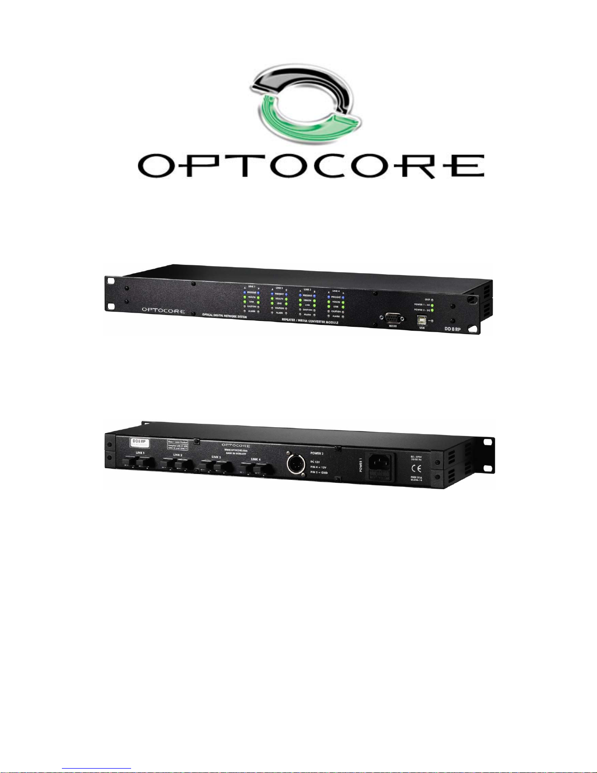
DD8RP
Operating Manual
Rev. 1.0
Operating Manual for OPTOCORE DD8RP
REPEATER / MEDIA CONVERTER MODULE
© Copyright 2007 All rights reserved
OPTOCORE GmbH
Lisbergstr. 7
81249 Munich
Germany
Page 2

DD8RP 2 / 15 rev. 1.0
Important Safety Instructions
• Please read this manual carefully.
• Please keep this operating manual in a safe place.
• Heed all warnings.
• Follow all instructions.
• This device may only be used in accordance to the information provided in this operating
manual. Ensure that all recommendations, especially the safety re commendations as detailed
in this operating manual, are followed before and during the usage of the device.
• Do not use this device near water, for example, in moist or damp rooms.
• Clean only with a dry cloth.
• Do not block or cover any ventilation slits. Install the device in accordance to the op erating
manual.
• Do not install or place the device near an y heat source such as radiators, power-amplifiers,
stoves, or any other heat producing equipment.
• Protect the power cord from being walked on, crushed, pinched, or damaged in any other way.
Pay special attention to plugs and sockets of the device.
• Never switch on power amplifiers before the complete system is stab le and the le vel meters o f
the OPTOCORE CONTROL software indicate a normal level.
• Do not place this device on an unstable table, tripod, cart, etc. The device may fall, causing
serious damage to the device, and a risk of injury.
• The device can only be removed from the power supply by pulling the plug. This must be
freely accessible at all times. The device has to be disconnected during lightning storms or
when unused for long periods of time.
• The device must be grounded; any disconnection of the grounding is not permitted.
• The switched-mode power supplies operate with high voltage. Coming into contact with them
can lead to considerable electric shocks, which may result in death.
• Only use attachments specified by the manufacturer.
• This device contains no user serviceable parts: only refer to authorized, qualified service
personnel for any servicing.
• Your warranty will be voided if you tamper with the internal components.
Page 3

DD8RP 3 / 15 rev. 1.0
Purchaser Information
• Operating Manual
Please read this manual – if you call for technical support, we’ll assume that you have. Study the
operating manual carefully in order to familiarize yourself with the device and its operation. It contains
numerous information and hints for the proper use of the device.
It cannot be excluded that this operation manual shows typographical mistakes or misprints; it is
however regularly revised.
Modifications, which serve the purpose of technical improvement of the device, may be carried out
without prior notification.
• Transport and Shipping
Always ensure the careful handling of the device. If possible transport or shipping should always
occur in special, shock-absorbing transport cases. If these are not available we recommend wellupholstered packaging such as the coated carton in which the device was delivered.
We strongly advise not to use simple flight-cases without rack-in-rack mounting.
• Environments
This device can be used in E1, E2, E3, E4, or E5 environments (as listed below) according to the
harmonized European standards EN55103-1 and EN55103-2 “Electromagnetic compatibility –
Product family standard for audio, video and audio-visual and entertainment lighting control apparatus
for professional use”
E1-Residental
E2-Commercial and light industrial
E3-Urban outdoors
E4-Controlled EMC environment e.g. broadcast and TV-studio
E5-Heavy industry
The product is intended for the use in moderate climate.
• Ventilation
Do not block or cover any ventilation slits. Install the device in accordance to the operating manual.
Leave sufficient ventilation space around the units (at least approx. 200mm ≡ 7,87" free space behind
the rear-panel) and care for free air movement near the ventilation-slits on both sides of the device.
Keep the rear of the rack open during operation. Do not set up the device close to equipment
producing a lot of heat, for example power-amplifiers. Leave enough space (minimum ½ RU) to any
heat emitting device. A DD8RP may be placed on top or beneath other Optocore products, except
DD32, without additional space.
• Water and Moisture etc.
To prevent fire or shock hazard do not expose device to the effects of direct sunlight, dust, water, or
rain during operation or storage.
• Cleaning
Only use a dry linen cloth to clean the device. In case of strong soiling moisten the cloth using a little
water and a small amount of household detergent. Never use cleansing agents containing solvents to
clean the device.
• Operating and Storage Temperature
Operating temperature: 0
°
C …50°C ≡ 34°F … 122°F; ensure proper ventilation
Storage temperature: -20°C …60°C ≡ -4°F … 140°F
Page 4

DD8RP 4 / 15 rev. 1.0
• Power Supply
The device can only be removed from the power supply by pulling the plug. This must be freely
accessible at all times. The switched-mode power supplies operate with high voltage. Coming into
contact with them can lead to considerable electric shocks, which may result in death.
Never disconnect the main plug by pulling the cable, always pull the plug itself.
Power-supply cords should be routed in such a way that they are not likely to be walked on, crushed,
pinched, or damaged in any other way. Pay special attention to the plugs and the sockets of the
device.
Replace a damaged power cable immediately.
The device must be grounded; any disconnection of the grounding is not permitted. Always ensure
the correct grounding of the device via the main plug. Never cover the grounding terminal of the plug
by means of insulation material!
• Fuse
The main fuse cannot prevent an unexpected malfunction of electrical components; it is rather there
to protect the user and its environment from damage. Therefore never try to replace the main fuse by
any other than the specified D1.0A type (1.0A, slow behavior). Never try to repair or bypass a blown
main fuse.
• Lightning
For additional protection of this device during lightning storms, or when it is left unattended and
unused for a long period of time, unplug the power line. This will prevent damage to the device due to
lightning and power line surges. Disconnection from the mains power supply can only be achieved by
removing the plug from the mains socket.
• Eye Safety
This product is a Laser Class 1 product. It complies with IEC 60825-1, FDA 21 CFR 1040.10, and
1040.11.
• Interference of external objects and/or liquids with the device
Never push objects of any kind into the device through openings in the casing. They may come in
touch with dangerous voltage points or short out parts that could result in a fire or electric shocks.
Never spill liquid of any kind on the device.
• Cables and Accessories
Only use attachments specified by the manufacturer.
Only use high quality cable material to connect the device. For the optical data connection exclusively
use the specified optical waveguide cables. If not in use, ensure that the optical connectors of both,
device and waveguide are closed with the provided lids.
Do not place this device on an unstable table, tripod, cart, etc. The device may fall, which can cause
injury and serious damage to the device. Any mounting of the device should follow the manufactures
instructions, and should use mounting accessory recommended by the manufacturer.
• Servicing
Do not attempt to service this device yourself.
This device contains no user serviceable parts: only refer to authorized, qualified service personnel
for any servicing.
The opening of the device is not required for operation as there are no user serviceable components
located inside the device. The operation of an opened device is not permitted. It can lead to damage
of components due to the absence of required ventilation. The device may not be serviced, altered or
modified without authorization of Optocore or an Optocore authorized distributor / dealer. Only
qualified service personnel may carry out repair and maintenance work. The warranty will be voided if
unauthorized manipulation occurred.
Page 5

DD8RP 5 / 15 rev. 1.0
CE-Conformity
This document confirms that the product DD8RP bearing the CE (Communauté Européenne) label meets all
requirements in the EMC directive 2004/108/EG laid down by the Member States Council for adjustment of legal
requirements. Furthermore the product complies with the rules and regulations of the low-voltage directive
2006/95/EG. This product bearing the CE label complies with the following standards, ratified by CENELEC
(Comité Européen de Normalisation Electrotechnique):
Electromagnetic compatibility – Product family standard for audio, video, audio-visual and
entertainment lighting control apparatus for professional use
EN 55103-1, Emission
EN 55103-2, Immunity
The authorised declaration and compatibility certification lies with the manufacturer and can be viewed on
request. Responsible as manufacturer is:
OPTOCORE GmbH, Lisbergstr.7, 81249 Munich, Germany
Represented by Marc Brunke, Managing Director
N.B. The awarding of the CE label confirms the compliance with legal directives issued for the manufacture and
marketing of electronic and electrical devices. As such the CE label is not a "seal of quality" but rather proof that
the device bearing the CE label is conform with the electromagnetic compatibility standards laid down in the
above named testing regulations.
Munich, 30.11.2007
Marc Brunke
Eye Safety
This product is a Laser Class 1 product. It complies with IEC 60825-1 and FDA 21 CFR 1040.10
and 1040.11.
Page 6

DD8RP 6 / 15 rev. 1.0
DD8RP REPEATER / MEDIA CONVERTER MODULE
Table of Contents
Important Safety Instructions....................................................................................................................................2
Purchaser Information..............................................................................................................................................3
CE-Conformity..........................................................................................................................................................5
Eye Safety................................................................................................................................................................ 5
Device Description ...................................................................................................................................................7
Front Panel...............................................................................................................................................................8
Rear Panel ...............................................................................................................................................................8
Device Details ..........................................................................................................................................................9
LINK Ports ....................................................................................................................................................9
Power Supply................................................................................................................................................9
Connectors and Cables............................................................................................................................................ 9
Starting Up .............................................................................................................................................................10
Hardware Connection .................................................................................................................................10
Connection Tables .................................................................................................................................................11
Technical Specifications......................................................................................................................................... 12
Dimensions and Weight .........................................................................................................................................13
Warranty and Liability............................................................................................................................................. 14
Shipping Contents..................................................................................................................................................14
Company Information.............................................................................................................................................15
Page 7

DD8RP 7 / 15 rev. 1.0
Device Description
Congratulations on your purchase of a DD8RP Repeater / Media Converter Module. The DD8RP will quickly
convince you with its advantages and will facilitate your day-to-day work.
The DD8RP features two possible applications. It can operate as a repeater in an Optocore network, if distances
between devices are longer than 700 m and the standard multimode fiber cables are used. Or it can function as
media converter from multimode to monomode fiber connections and vice versa. The four repeaters / media
converters work protocol independent, they can be implemented in networks based on protocols such as Ethernet
as well. The unit is specially designed for low power consumption and provides a DC 12 V power supply. Battery
packs can supply the power, if no mains supply is available. This can immensely simplify outdoor applications.
The flexibility to use the DD8RP as repeater and converter is achieved by receptacles for SFP (Small Form-factor
Pluggable) optical transceivers. Eight receptacles form the four independent LINK interfaces; each LINK can
consist of two SFPs with dual LC type connectors. The function of a LINK as repeater or converter depends on
the implemented optical transceiver. This allows the configuration exactly appropriate for the application. E.g. one
LINK may extend the distance between two Optocore devices in an OPTOCORE
®
OPTICAL DIGITAL
NETWORK, while the other LINKs are used in totally different networks with non-Optocore protocols.
LEDs on the front give detailed information about the status and operating state of each LINK. They indicate if a
malfunction of any connection could influence the high quality data transmission.
Two power supplies with automatic switchover and individual connectors provide a high grade of safety. The first
power supply is for AC mains input including the unique 400 V tolerant Optocore design. An over-voltage-monitor
lights the OVP (Over Voltage Protection) status LED during an over voltage condition, simultaneously
suppressing the normal function of the device. The second power supply is for DC 12 V, equipped with a male 4-
pin connector. The DC power supply is compatible with battery packs, UPSs (Uninterruptible Power Supply) or
standard AC adapters.
Due to SMD production the DD8RP fulfills the demand of highest digital standards occupying only one rack unit of
a 19" rack. The FPGA (field programmable gate array) based concept of the internal logic circuitry permits
updating of the hardware via the units remote ports, ensuring a continual state-of-the-art device.
Page 8
DD8RP 8 / 15 rev. 1.0
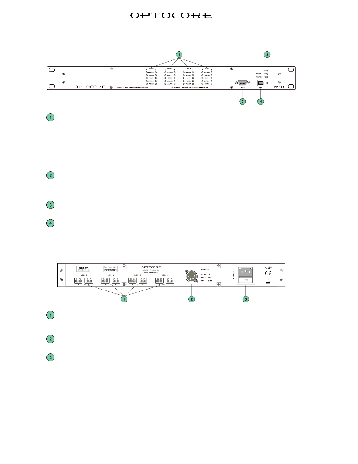
Front Panel
LINK 1 … 4: Indicates the status of each optical transceiver:
A: Status at LC connector A
B: Status at LC connector B
PRESENT: Fiber transceiver (SFP) installed
HEALTH: Fiber transceiver operates within specified parameters
LINK: Optical signal detected
CAUTION: Received optical signal is low but still operational
ALARM: Received optical signal is too low for proper operation
OVP LED: Indicates over-voltage protection (> 300 V
AC
)
PWR 1 LED: AC Power supply 1 is working correctly
PWR 2 LED: DC Power supply 2 is working correctly
RS232 plug: D-Sub-9 RS232 connection for remote control and update via PC
USB plug and LED: USB connection for remote control via PC
LED ON indicates USB is connected;
LED blinking indicates data traffic
Rear Panel
LINK 1 … 4: Independent LC-type optical interface, equipped with SFP transceivers. Type
of transceivers depend on costumer’s order.
POWER 2: Input for DC 12V / 1A power supply
POWER 1: Mains input for AC power supply 1 (100 … 240 V)
Page 9

DD8RP 9 / 15 rev. 1.0
Device Details
LINK Ports
Four independent LINK ports provide receptacles for SFP optical transceivers. Each LINK can be equipped with
two SFPs with two LC-type connectors. The advantage of this concept is obvious. Each port holds the SFP
needed in the particular application. They can be changed without opening the device. The multimode full duplex
SFP transceiver (850nm) or monomode full duplex SFP transceiver (1300nm) can be purchased with the device
or can be ordered later.
The specification of the ports as A or B serves only for orientation. A dual LC cable with an input and output signal
connected to port A will be transferred to port B, either refreshed by the repeater or refreshed and converted to
another media type.
The DD8RP is not limited to be used in Optocore networks. It can operate in all sorts of networks no matter which
protocol is the base of the data transmission. The four LINKS are functioning totally independent; so one LINK
can serve in an Optocore network, the next one in a 1 Gbit-Ethernet and the others in completely different
networks.
Power Supply
The device is equipped with two power inputs and power supply units. If one power supply fails, due to
malfunction of the feeding power line or the power supply unit itself, the device will automatically switch over to
the other power supply unit.
One power supply unit operates with mains voltage of 100 ... 240 V and frequency of 50 … 60 Hz. Thus the
device can be used throughout the world without any adjustments or transformers.
The power supply unit is 400 V
AC
tolerant and protected against high current. The OVP (Over Voltage Protection)
LED on the front will indicate over voltage at > 300 V, simultaneously suppressing the normal function of the
device. When the OVP LED is lit, immediately disconnect the device from the power line to prevent any damage
to the device. The power input has a fuse, replaceable without opening the device.
Never bypass the fuse and only use the specified type.
Be aware that the switched-mode power supply operates with high voltages! Coming into contact with it
can lead to considerable electric shocks that may result in death! To prevent electric shocks do not
remove any covers!
The second power supply operates with 9-15 V / 1 A AC or DC. The low voltage can be provided by a wide range
of alternatives such as battery packs, UPSs (Uninterruptible Power Supply) or standard AC adapters. Specially in
temporary outdoor applications with long distances between devices, e.g. at a race course or a road race, this
simplifies the power supply. No generator or long power cables are necessary. The unit is specially designed for
low power consumption. A battery pack with a sufficient capacity can easily supply the required power.
Connectors and Cables
Optical Connection
The type of the optical fiber cables depends on the optical transceivers. The connectors are LC-type.
RS232-Connection
Shielded, standard 1-modem cable is sufficient for the RS232 port.
USB-Connection
For the USB-port use a standard PC/device cable.
Mains-Connection
For the power supply 1 standard power cords with IEC C13 socket can be used.
12V-Connector
For the power supply 2 a cable with 4 pole female XLR connector can be used.
Page 10
DD8RP 10 / 15 rev. 1.0
Starting Up
The DD8RP is functioning independent of the format and structure of the connected devices. So no software
configuration is necessary, no ID has to be set and there is no limitation of the number of DD8RP implemented in
the network.
Hardware Connection
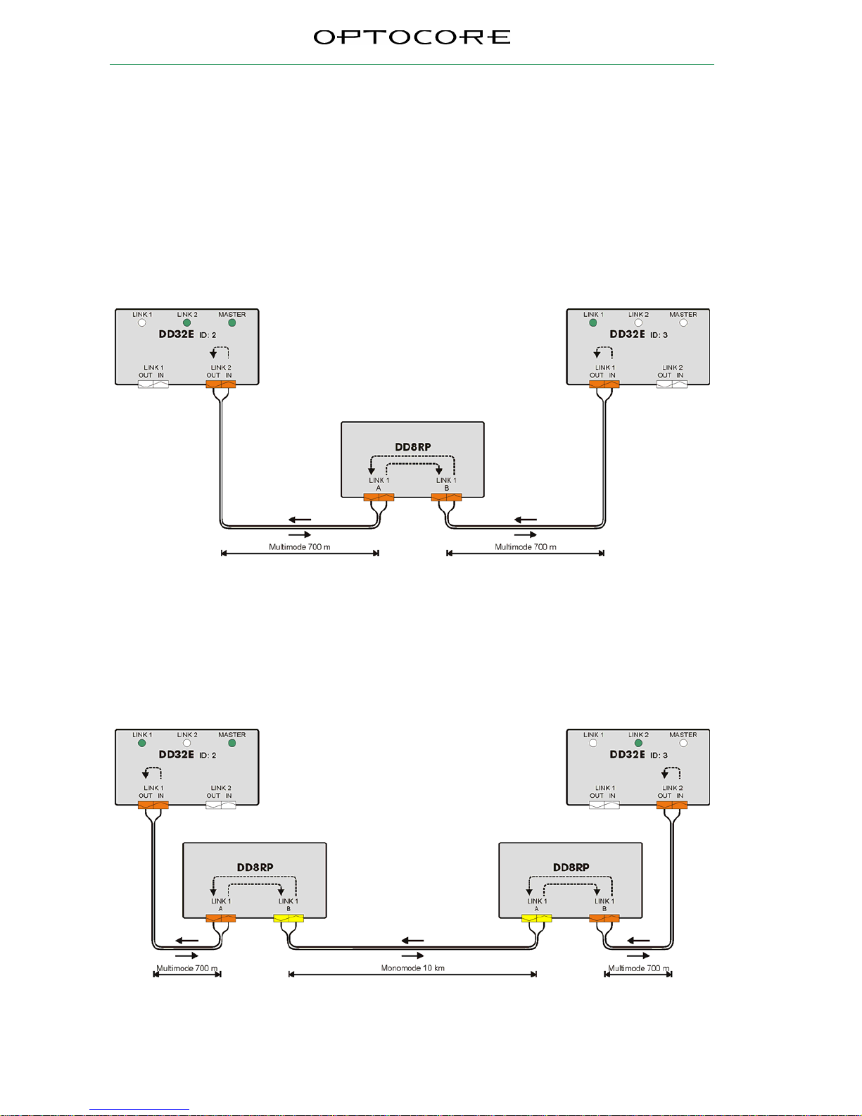
Each LINK is working autonomous. There are four separate repeaters or converters. To extend the distance
between two devices, e.g. two DD32E as shown in Fig. 1 and Fig. 2, one LINK interface of the DD8RP equipped
with the appropriate SFP optical transceivers is needed.
In Fig. 1 both receptacles of LINK 1 are equipped with multimode transceivers (orange). The LINK is functioning
as a repeater in order to extend the distance of a multimode connection. Port A of the LINK 1 is used as interface
to the DD32E with ID 2; port B as interface to the DD32E with ID 2.
Fig. 1: DD8RP between two DD32E, functioning as repeater in order to extend the distance of the
multimode connection.
The second example in Fig. 2 shows an application where the two DD8RP work as repeater and media converter.
The first DD8RP functions as a converter from multimode to monomode, the second DD8RP converts the signal
back to multimode. The ports of LINK 1 connected to the DD32E are equipped with multimode SFPs (orange).
The second ports of LINK 1 contain standard monomode SFPs (yellow) in order to enable distances up to 10 km.
SFPs for distances up to 70 km can be purchased on request. The converters refresh the signal as well. The full
cable length, 700 m between multimode transceivers and 10 km between monomode transceivers, is available.
Fig. 2: Two DD8RP as multimode to monomode and vice versa converters.
Page 11
DD8RP 11 / 15 rev. 1.0
Connection Tables
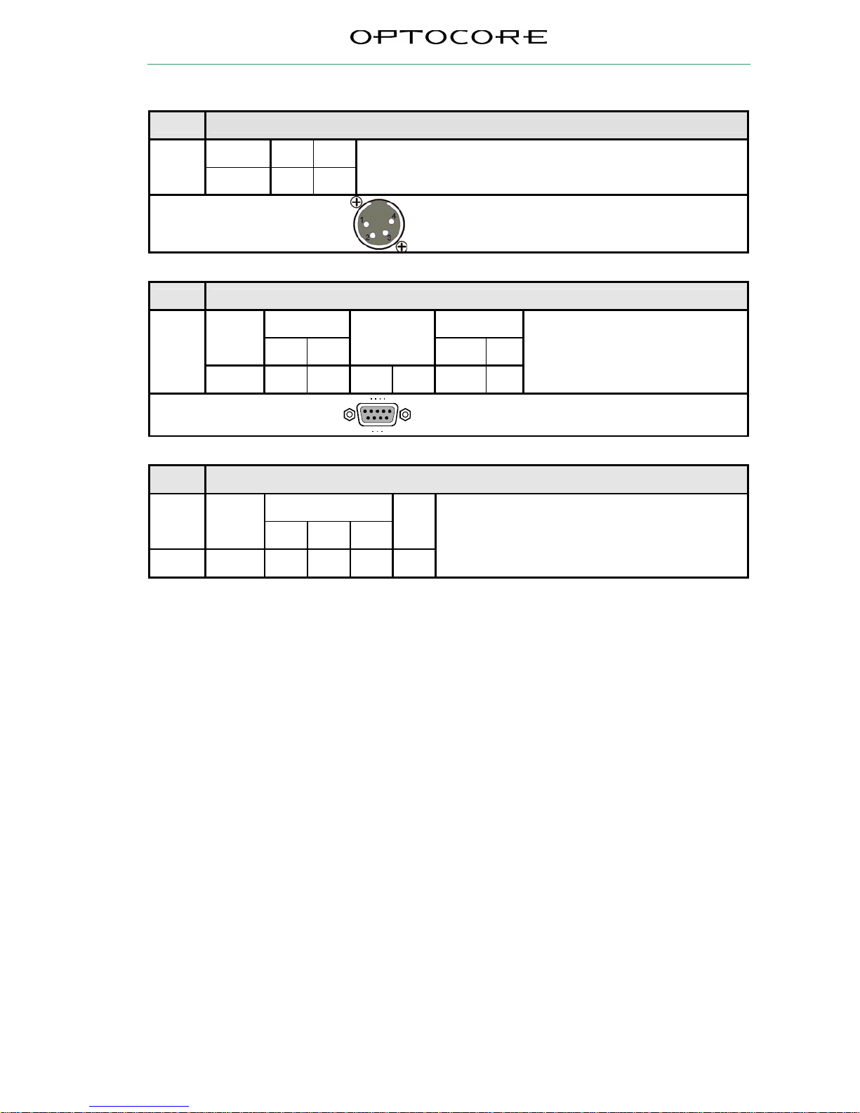
Pin-out DC-12V 1A
12V GND
Pin 4 1
4 pole male XLR
Pin-out RS232-Port
RS232 Power
Channel
RXD TXD
Internally
Bridged
+5VS GND
Pin 3 2 1, 4, 6 7, 8 9 5
Use 1-modem cable, male – female, to
connect to PC
D-Sub-9- female
5
1
9
6
Locking system acc. to 4-40 UNC
Pin-out USB-Port
USB
Channel
VBUS D - D +
GND
Pin 1 2 3 4
USB device-connector
Page 12

DD8RP 12 / 15 rev. 1.0
Technical Specifications
Link Ports
Input, output dual – full bandwidth
Connection Small Form Pluggable (SFP) optical transceiver 4 Duplex LC
Compatible Protocol Protocol independent
Transmission Full duplex
Data rate Standard 100 Mbps to 1 Gbps
On request 2 Gbps
Optical wave guide cable lengths e.g. Multimode fiber 50 µm ≤ 700 m
e.g. Multimode fiber 62.5 µm ≤ 350 m (not recommended)
e.g. Monomode fiber 9 µm ≤ 70 km
RS232 Port
Convention EIA / TIA-232
Data channels Digital control data R x D, T x D
Data rate Up to 115200 Baud
External supply Current limited + 5 V
USB Port
Remote control input No transmission purposes
Power 1
Automatic switch-over to DC power supply
Type Switch-mode, universal input
Mains voltage 100 ... 240 V, 400 V
AC
tolerant
Frequency 50 ... 60 Hz
Power consumption 4-14 VA (dependent of number of SFPs installed)
Fuse D1.0 A, slow behavior, glass 5 mm x 20 mm, acc. to UL 48-14
Inrush current limit ≤ 7 A
Protection circuit 400 V
AC
tolerance, over-voltage, over-current and over-temperature monitor
Security classification Class 1: basic insulation, connected to the protective grounding conductor
Security regulations Harmonized European standard EN60065: 2002
Mains connector Including EMI-filter, a fuse and spare-fuse, acc. to IEC-950
Cooling Via surface and ventilation-slits on both sides
Power 2
Type 12 V DC, compatible to battery packs, UPS, standard AC adapters
Voltage 9 - 15 V AC or DC
Power consumption 0,6 VA – idle, plus 0,45 / 0,6 VA per SFP installed (multimode / monomode)
Protection circuit Electronic fuse
12 V device connector 4 pole XLR male
12 V cable connector 4
p
ole XLR female (e.g. Neutrik NC4FX
)
Cooling Via surface and ventilation-slits on both side
Page 13
DD8RP 13 / 15 rev. 1.0
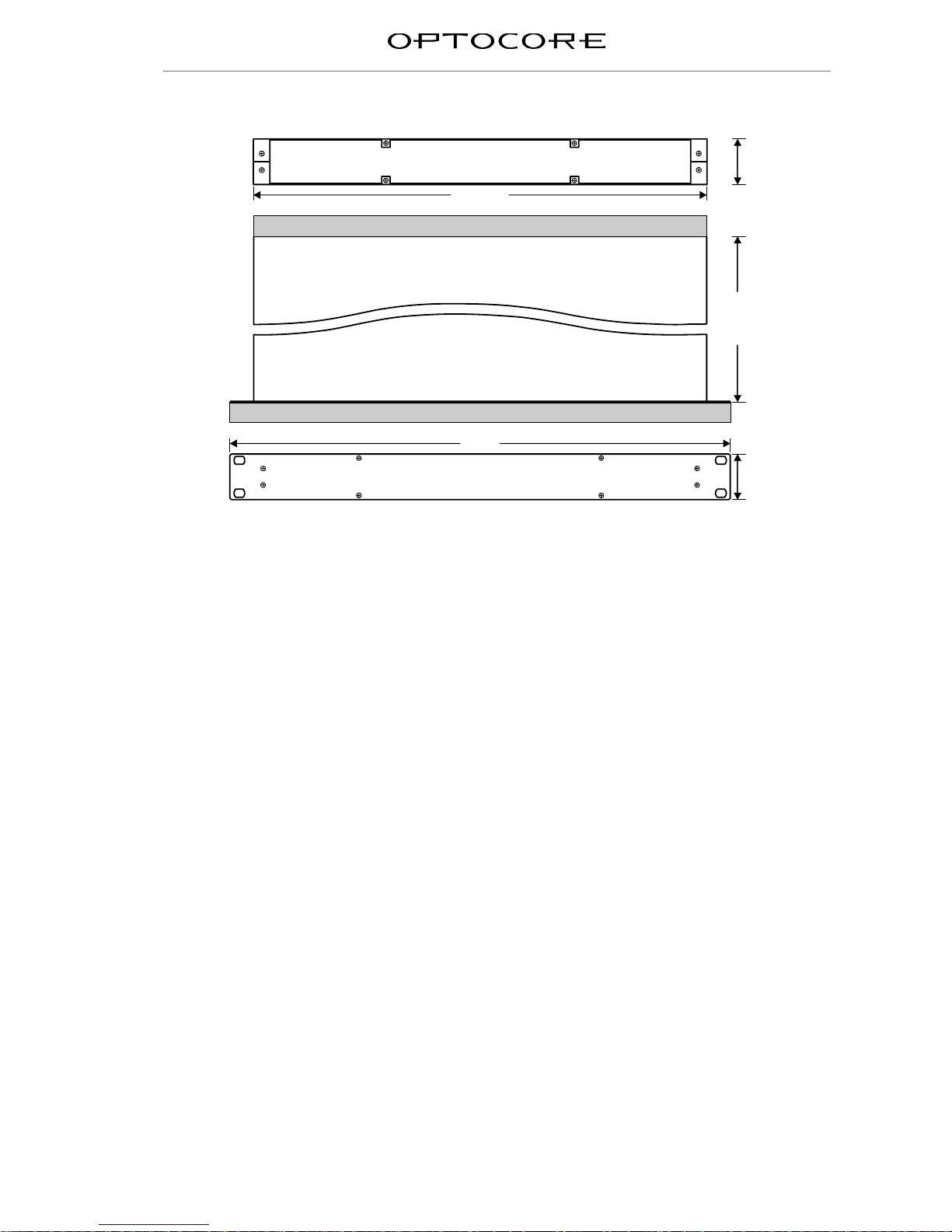
Dimensions and Weight
Units:
mm [inch]
483 [19]
438 [17.25]
44 [1.73]
136 [5.35]
44 [1.73]
1RU
Front-plate, Front-elements, Ha ndles: Add 6 [0.24]
Rear-elements: Add 15 [0.6]
Weight
2.0 kg ≡ 4.4 lbs
Modifications that serve the purpose of technical improvement of the de vice may be carried out without
prior notification.
Page 14

DD8RP 14 / 15 rev. 1.0
Warranty and Liability
Summary of Warranty
Optocore DD8RP is warranted against defects in material and workmanship for 24 months.
This warranty covers the original purchaser only and is not transferable. Valid evidence for warranty is the official
Optocore invoice issued by the distributor / dealer.
Optocore will, at its discretion, repair or replace a defective product, providing that the defect has appeared under
normal operating conditions.
This warranty does not cover damage from acts of God, accident, abuse, neglect, contamination, unauthorized
modification or misuse, operation outside of the environmental specifications for the product, improper site
preparation or maintenance, or abnormal conditions of handling. This would include over-voltage failures, and
conditions outside of the products specified ratings, problems with buyer-supplied software or interfacing, or
normal wear and tear of mechanical components. Optocore or its distributor / dealer will acknowledge the
evaluation of warranty after inspection.
Devices on which the Serial Number has been removed or defaced are not eligible for warranty service.
Failure to properly package and protection of the product during shipping may void this warranty.
How to Obtain Warranty Service
To return a defective product, please contact your distributor / dealer. Our web site: http://www.optocore.com/
provides a complete list of Optocore distributors / dealers.
Always ensure the careful handling of the device. If possible transport or shipping should always occur in special,
shock-absorbing transport cases. If these are not available we recommend well-upholstered packaging such as
the coated carton in which the device was delivered.
We strongly advise not to use simple flight-cases without rack-in-rack mounting.
Declaration of Liability
Optocore accepts no liability for damage caused to other devices through operation of the DD8RP device.
Optocore is not liable for any damage caused by shipping accidents, misuse, abuse, operation with incorrect AC
voltage, operation with faulty peripheral equipment, or improper or careless installation of the device.
Optocore accepts no claims for compensation whatsoever (e.g. cancellation of events).
Shipping Contents
The standard shipment of a DD8RP device contains the following:
• 1 DD8RP device
• Number and type of SPF transceivers according to customer’s order (not included in standard
shipment)
• 1 D1.0A (1.0A, slow behavior) replacement fuses per device
inserted next to the operational fuses in the power supply inlet.
• 1 operating manual
Any additionally purchased equipment such as optical wave-guide cables in required lengths, D-Sub cables and
adapters, RS232 cables, and international electric cables have been supplied on your request and your purchase
order and cannot be listed in the above.
Page 15

DD8RP 15 / 15 rev. 1.0
Company Information
Mailing Address:
OPTOCORE GmbH
Lisbergstr. 7
D-81249 Munich
Germany
Telephone:
+49 – (0)89 – 8999640
Facsimile:
+49 – (0)89 – 89996455
Internet:
www.optocore.com
Email:
 Loading...