

Page 1

FOTEMP1
USER MANUAL
Page 2

TABLE OF CONTENT
SAFETY 04
INTRODUCTION 06
PRODUCT SPECIFICATIONS 08
QUICK START 10
GETTING STARTED 13
SENSOR CONNECTION 15
SENSOR HANDLING 17
SENSOR / CONNECTOR CLEANING 19
SOFTWARE INSTALLATION 20
ONE POINT CALIBRATION 21
SERIAL COMMUNICATION 22
VIEWING TEMPERATURE DATA 23
ANALOG OUTPUT / LED 24
LOGGING 25
SAVING / PRINTING 27
Page 3

USER MANUALFOTEMP1
3
GENERAL
The ber optical thermometer described in the
operating instructions has been designed and
manufactured using state-of-the-art technology.
All components are subject to stringent quality
and environmental criteria during production.
These operating instructions contain important
information on handling the instrument. Working safely requires that all safety instructions
and work instructions are observed.
Observe the relevant local accident prevention
regulations and general safety regulations for
the instrument‘s range of use.
The operating instructions are part of the
product and must be kept in the immediate
vicinity of the instrument and readily accessible
to skilled personnel at any time.
Skilled personnel must have carefully read and
understood the operating instructions prior to
beginning any work.
The manufacturer‘s liability is void in the case
of any demage caused by using the product
contrary to its intended use, non-compliance
with these operating instructions, assignement
of insuciently qualied skilled personnel or
unauthorised modications to the instrument.
The general terms and conditions contained in
the sales documentation shall apply.
Subject to technical modications.
Further information: Internet-adress:
www.optocon.de
Page 4

USER MANUALFOTEMP1
4
SAFETY
This manual contains important information to
ensure personal safety and to prevent damage.
Explanation of symbols:
Information: points out useful tips, recommendations and information for ecient and
trouble-free operation.
Caution: indicates a potentially dangerous
situation that can result in light injuries or
damage to equipment or the environment, if
not avoided.
Warning: indicates a potentially dangerous
situation that can result in injury or death, if not
avoided.
Skilled personnel
Skilled personnel are understood to be personnel who, based on their technical training,
knowledge of measurement and control technology and their experience and knowledge of
country-specic regulations, current standards
and directives, are capable of carrying out the
work described and independently recognizing
potential hazards.
Intended use
The instrument has been designed and built
solely for the intended use described here, and
may only be used accordingly. The technical
specications contained in these operating
instructions must be observed.
Page 5

USER MANUALFOTEMP1
5
UNPACKING, INSPECTION, SERVICE
When unpacking and inspecting your system
components, you need to do the following:
1. Check all materials against the enclosed
packing list.
2. Carefully unpack and inspect all components
for visible damage.
3. Save all packing materials, until you have
inspected all components and nd that there
is no obvious or hidden damage.
4. Before shipment, each instrument is assembled, calibrated, and tested. If you note any
damage or suspect damage, immediately
contact us.
Contact Optocon AG in case of a malfunction or
service request.
Technical support can be contacted by telephone Monday-Friday between 8:30 to 17:00
o‘clock: +49 (351) 3101957
or email: [email protected]
Send RMA shipments to:
Optocon AG, Pohlandstraße 17, 01309 Dresden,
Germany
Disposal
Inoperable instruments must be disposed of in
compliance with local regulations for electronic
materials.
Page 6
USER MANUALFOTEMP1
6
INTRODUCTION
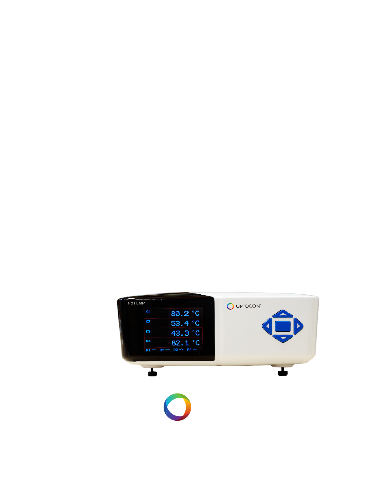
The ber optic thermometer FOTEMP1 is ideal
for the use in EMI, RFI, microwave and high
voltage environments. It combines innovative
design with user-friendly functionality. The new
ber-optic thermometer FOTEMP1 combines
innovative design with user-friendly functionality. The modern design makes the temperature
measurement even easier and oers complete
immunity to RFI, EMI, NMR and microwave
radiation.
The FOTEMP1 has an innovative appearance:
It has a larger screen and a modern keyboard
which makes the data acquisition and control of
the device even easier. The user-friendly display
supports high-precision measurements, while
the color LCD display oers excellent readout
of the measurement values even in low light
conditions. The menu
supports two languages,
German and English.
With its compact design,
it ts perfectly into any
environments. Various
interfaces, analog and relay
outputs make the device very
versatile. The extensive software „Fotemp Assistent“ allows a detailed evaluation via PC with
direct export of data to an Excel spreadsheet.
The FOTEMP1 has a measuring range from
-200°C to +300°C. It measures with the usual
Optocon accuracy of ± 0.2°C. The ber optic
thermometer oers complete immunity to RFI,
EMI and microwave radiation, making it ideal
for environments where the use of conventional temperature measuring instruments is
excluded due to extreme conditions.
It is compatible with all our ber optic temperature sensors and is ideal for any applications in
the laboratory and in industry.
Page 7

USER MANUALFOTEMP1
7
The outer jacket of the ber optic temperature
sensors is made out of teon, at the sensor tip a
GaAscrystal (gallium arsenide) is attached. The
probe sensor is completely non-conductive.
Optocon’s ber optic sensors oer complete
immunity to RF and microwave radiation with
high temperature operating capability, intrinsic
safety, and non-invasive use. The probes are
also designed to withstand harsh and corrosive
environments.
Starting at a light wave length of 850nm GaAs
becomes optical translucent. Since the position
of the band gap is temperature dependent, it
shifts about 0.4nm/Kelvin.
The measurement device contains a light source and a device for the spectral detection of the
band gap. This guaranties fast, repeatable and
reproducible measurements.
Via the analog outputs and thanks to its
accompanying software “FOTEMP-Assistant”,
measurement results can be easily controlled
and monitored.
Over the entire life of the system calibration is
not required to remain within the specications.
Page 8

USER MANUALFOTEMP1
8
PRODUCTS SPECIFICATIONS
Number of channels
1
Power supply
100-240VAC / 50-60Hz
Power consumption
> 10VA
Measuring range - 200°C to +300°C
Accuracy +/- 0.2 °C
Resolution
0,1 °C
Sampling rate/Channel
250ms
Analog output 0-10V or 4-20mA
Interface RS-232 or RS-485 or USB
Relay output
1
Data logging Log sequenz via software
Display 7,1cm (2,8“) LCD-TFT color display
Connector type
ST
Form factor
IP54
Storage temperature -20°C to +70°C
Operating temperature -20°C to +60°C
Weight
1,2 kg
Dimensions
205 x 267 x 81 mm
Material ABS/PC in RAL9003
Software FOTEMP-Assistent
Page 9

USER MANUALFOTEMP1
9
PRODUCT SPECIFICATIONS
Data export Via interfaces
Warranty 2 years
Probes All ber optic temperature probes from Optocon AG can be
connected
Calibration
To ensure an accurate temperature measurement in critical areas, we oer a comprehensive
calibration service for our ber optic temperature measurement instruments. Through our
modern labs and our qualied sta we can guarantee you a very accurate and fast calibration.
Within a few days you get your unit back and
can start your ber optic measurement projects.
For each calibrated measurement instrument
by us, a full certicate of test results is supplied.
Your ber optical thermometer Icomes
factory calibrated. An annual re-calibration is
not necessary, except for internal company
regulations. All calibrations are performed at
our factory. For each calibrated measurement
instrument by us, a full certicate of test results
is supplied.
Your account manager is available Monday to
Friday 8:30 to 17:00 clock personally by phone
+49 (351) 3101957. In addition, you are welcome to send an email message to tell us your
concern. We will get in touch with you as soon
as possible.
Our delivery address:
Optocon AG
Pohlandstraße 17
01309 Dresden, Germany
Telefon: +49 (0)351 310 1957
Fax: +49 (0)351 311 1951
E-mail: [email protected]
Page 10
USER MANUALFOTEMP1
10
QUICK START
This quick reference guide gives you an
overview for quick usage. However, it can not
replace extensive literature with important
information and safety warnings.
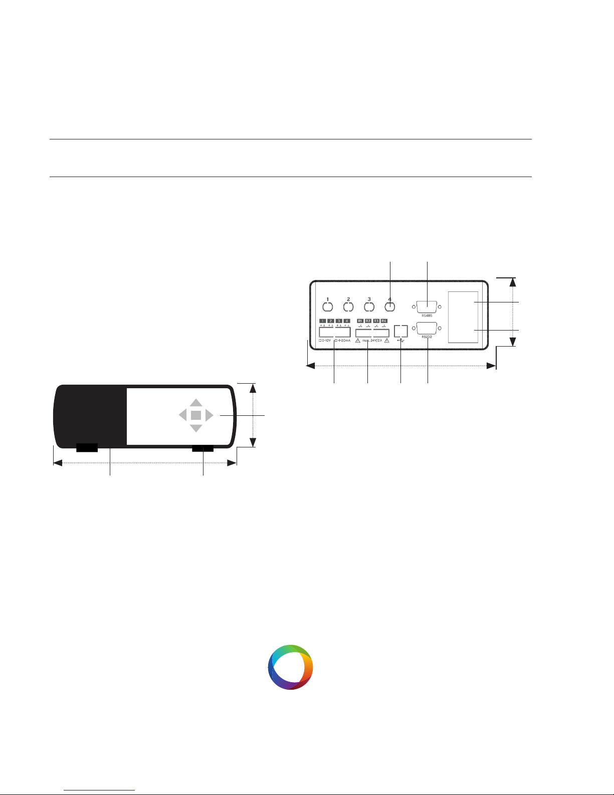
Front panel
The following gure shows the thermometer
front panel:
The following presents an easy overview and
description of the user interfaces and instructions on how to use the thermometer.
Back panel
The following gure shows the thermometer
back panel:
1) Keypad
For FOTEMP usage a 5 piece keypad is available.
All functions, such as relay settings, one-point
calibration can be performed both via the keypads and using the software „Fotemp-Assistent“.
The middle key gives access to the system
menus. To navigate in the menu use the keys
LI and RE
205 MM
81 MM
1
2
3
205 MM
81 MM
4
5
6
7
891011
Page 11

USER MANUALFOTEMP1
11
(left and right). Conrm your selection also by
pressing the middle key. To change the values,
use the up and down keys.
2) Fold out stands
Integrated fold out stands; turn to individually
adjust height of front panel.
3) LCD-TFT display
The LCD display shows the temperature
readings for the user selected channels. The
temperature values are displayed either in Grad
Celsius (°C) or Fahrenheit (F). Selections can be
made in the menu via the keypad.
4) Sensor connectors
These are ST type connectors, mating to each of
the 4 optical temperature sensors. If you need
to extend the ber optic temperature sensor
please use the extension cables also available
from Optocon AG. For thermometers that have
only 1 or two channel(s), only 1 or t2 sensor
connectors are used.
5) RS-485 interface
This interface is used to congure and extract
information for the instrument.
6) Power switch
Make sure the power supply in connected and
powered.
7) Power switch
Please use only the power supply provided.
8) RS-232 interface
9) USB interface
10) Relay output
Page 12

USER MANUALFOTEMP1
12
11) Analog output
The device has an analog output for each temperature channel. Prior to shipment, the ber
optical thermometer is factory set to one of
the following congurations: 4-20mA or 0-10V.
The analog output is located on the back panel
below the ST socket as BNC type. The limits are
set to 0°C and 300°C. The temperatures correspond to values between 4-20mA or 0-10V. If no
temperature sensor is connected, the maximum
value is considered.
Page 13

USER MANUALFOTEMP1
13
GETTING STARTED
1. Plug the provided optical ber temperature
sensors to the ST-socket on the
backside of the instrument. Please make sure
that the sensor marked as K1 is connected to
ST-socket number 1. Sensor marked with K2
must be connected to ST-socket number 2 etc.
2. Connect the provided RS-232 interface cable
to the thermometer and a free serial port of the
PC or Notebook.
3. To power the thermometer please use the
provided power supply.
4. After powering and switching the thermome-
ter on, Iour company logo and temperature values will be displayed for the dierent channels.
5. Now the thermometer is ready for measure-
ment.
If no sensor is connected, the display will show
„ Sensor?“.
Caution! The ber optical thermometers
only function with Optocon ber optic temperature sensors. Please do not use temperature
sensors of other brands.
General installation guidelines
Please read the instructions for installing the
ber optic instrument carefully. Please note
especially the order of the instructions exactly.
Sensor handling
The sensor consists of a ST-plug at the end
and a gallium arsenide crystal at the tip of the
sensor. The crystal is sensitive and should not be
exposed to excessive mechanical stress.
Please Please note the information about the
bending radius of the sensor on page 17. A forcible bending of the sensor leads to breakage of
the ber. In this case the sensor is damaged and
Page 14

USER MANUALFOTEMP1
14
needs to be repaired / replaced.
Connection with PC:
Before establishing the rst connection, please
check whether the FOTEMP device is
connected to the power supply and the PC via
the RS-232 cable respectively.
Connection with sensors:
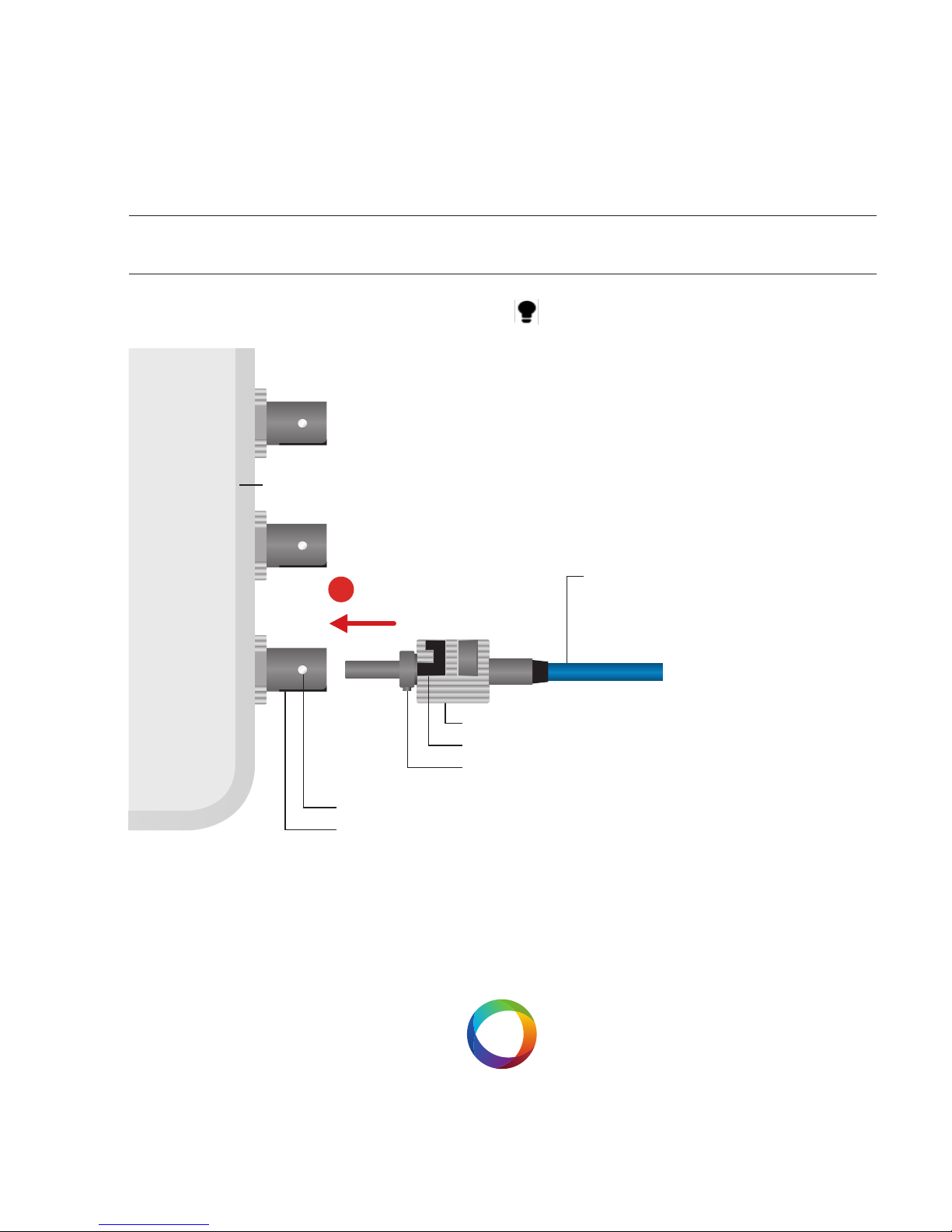
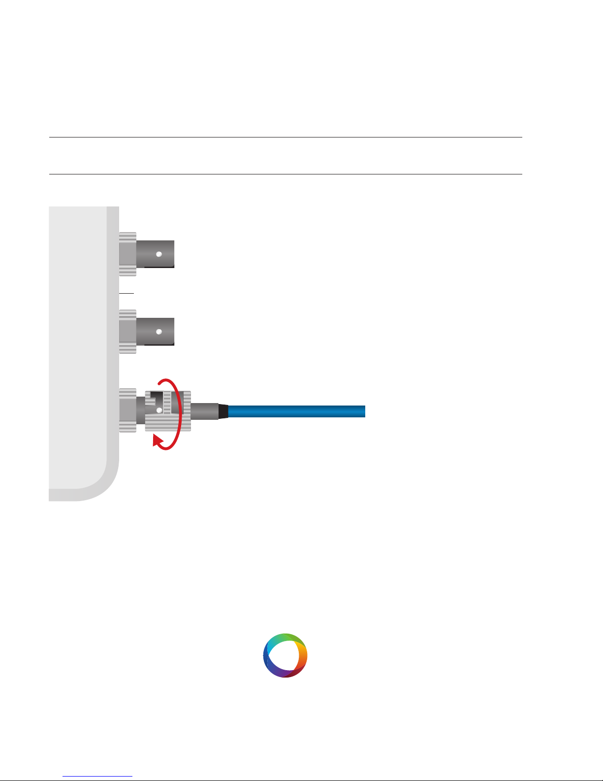
The temperature sensors are connected via the
ST-plugs to the BNC sockets at the back panel.
Please note to insert the plugs pushing slightly
against the spring pressure and to turn with a
clockwise rotation.
All ber optical temperature sensors of Optocon
AG can be connected.
Page 15
USER MANUALFOTEMP1
15
SENSOR CONNECTION
To ensure accurate measurements and long life
of the ber optic sensors and instruments, it is
necessary to clean them regularly.
Any channels not in use must be protected
with supplied dust caps.
More information about cleaning can be found
on page 19.
EXTENSION CABLE
STCONNECTOR
1
LOCKING NUT
PINS
FERRULE KEY
BNCSOCKET
FOTEMP
Page 16
USER MANUALFOTEMP1
16
FOTEMP
Test of sensor functionaly
To test the functionality of the sensor, you can
place the sensor into a test liquid, of which the
temperature is known (eg boiling water). The
sensor will respond with the given temperature
within a few seconds.
If no temperature is displayed please re-install
the software and check if the sensor has contact
to the measuring object.
Page 17
USER MANUALFOTEMP1
17
SENSOR HANDLING
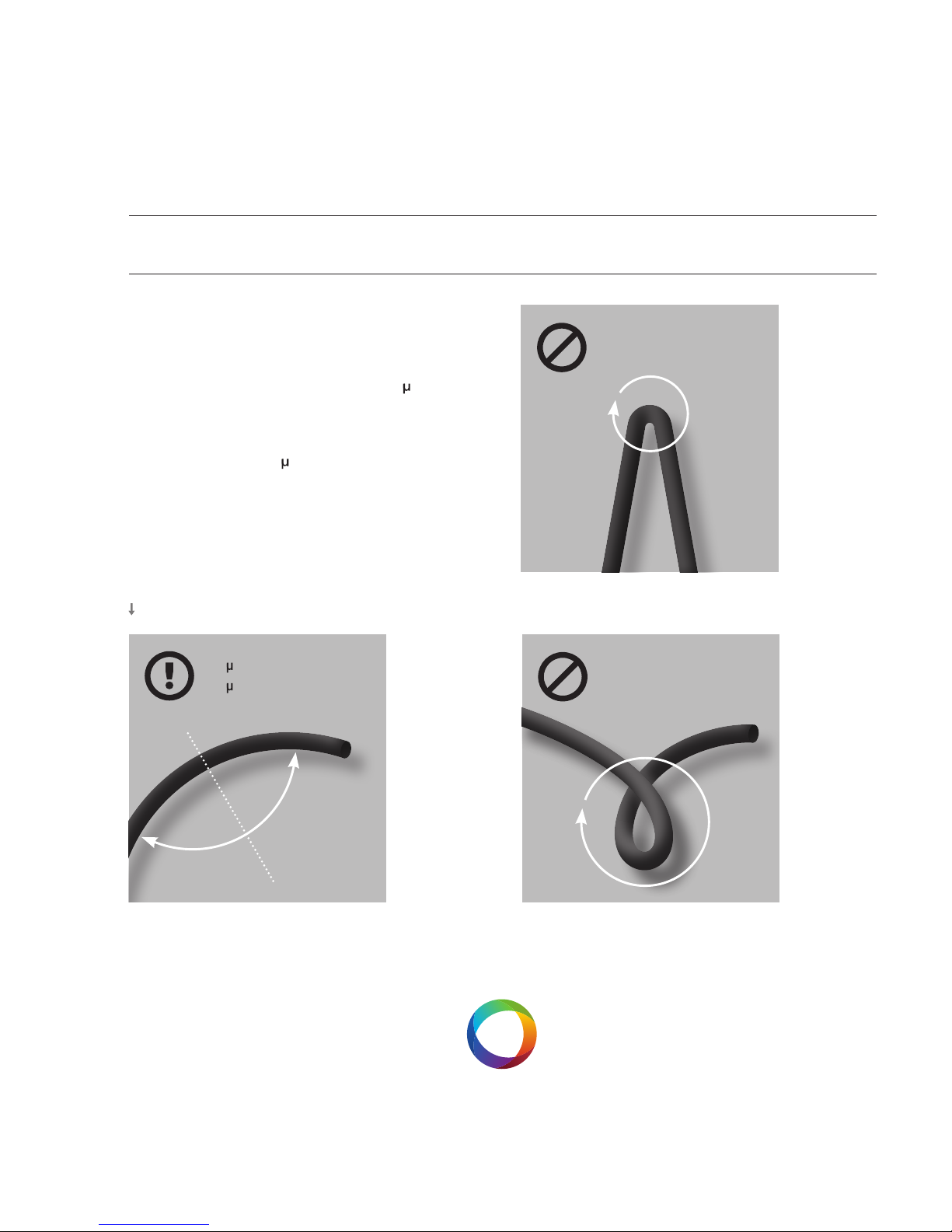
General advise
Bending radius:
For bers with a core diameter of 200 m have
a maximum short time bending radius of 4cm
applies; long term usage of 8cm. Fibers with a
core diameter of 400 m have a maximum short
term bending radius of 8cm; long term of.
Bending radius
200 m = R
MIN
4 c m
400 m = R
MIN
8 c m
Avoid sharp turns!
Avoid tight loops!
Page 18
USER MANUALFOTEMP1
18
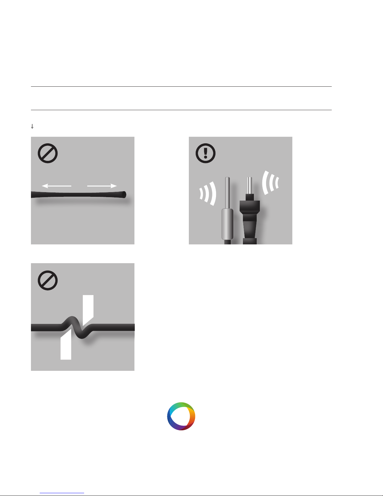
Storage
The sensor should be in its delivery box.
Avoid stretching!
Mechanical load
Avoid pinch points!
Avoid shocks on sensor tip and
connector head!
Page 19
USER MANUALFOTEMP1
19
CLEANING OF SENSOR CONNECTORS AND PLUGS
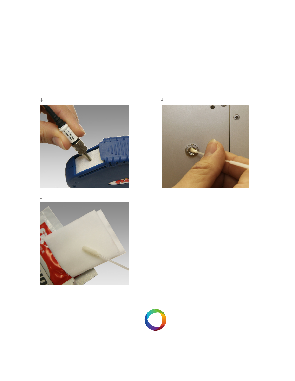
Instructions
Clean the ST connector of the sensor with the
connector cleaner. Softly press the connector
on the cloth tape and rotate across the tape
while rotating the connector.
You can clean up to 6 connectors before advancing the tape. Tear o excess tape as required.
Take a swab and wet it with the isopropanol
wipes. In rotating motion smoothly insert swab
into the internal connector of the conditioner.
Avoid using cotton swabs.
Step 1
Step 2
Step 3
Page 20
USER MANUALFOTEMP1
20
SOFTWARE
Installation
The accompanying software “FoTempMKT”
establishes the connection to the FOTEMP
device, displays the measured temperatures
graphically and saves the temperature data into
a log le, if needed.
For installation simply copy the le „FOTEMPMKT.EXE“ to a local hard disk folder and start
the program.
Set up
Before establishing the rst connection, please
check whether the FOTEMP device is
connected to the power supply and the PC via
the RS232 cable respectively.
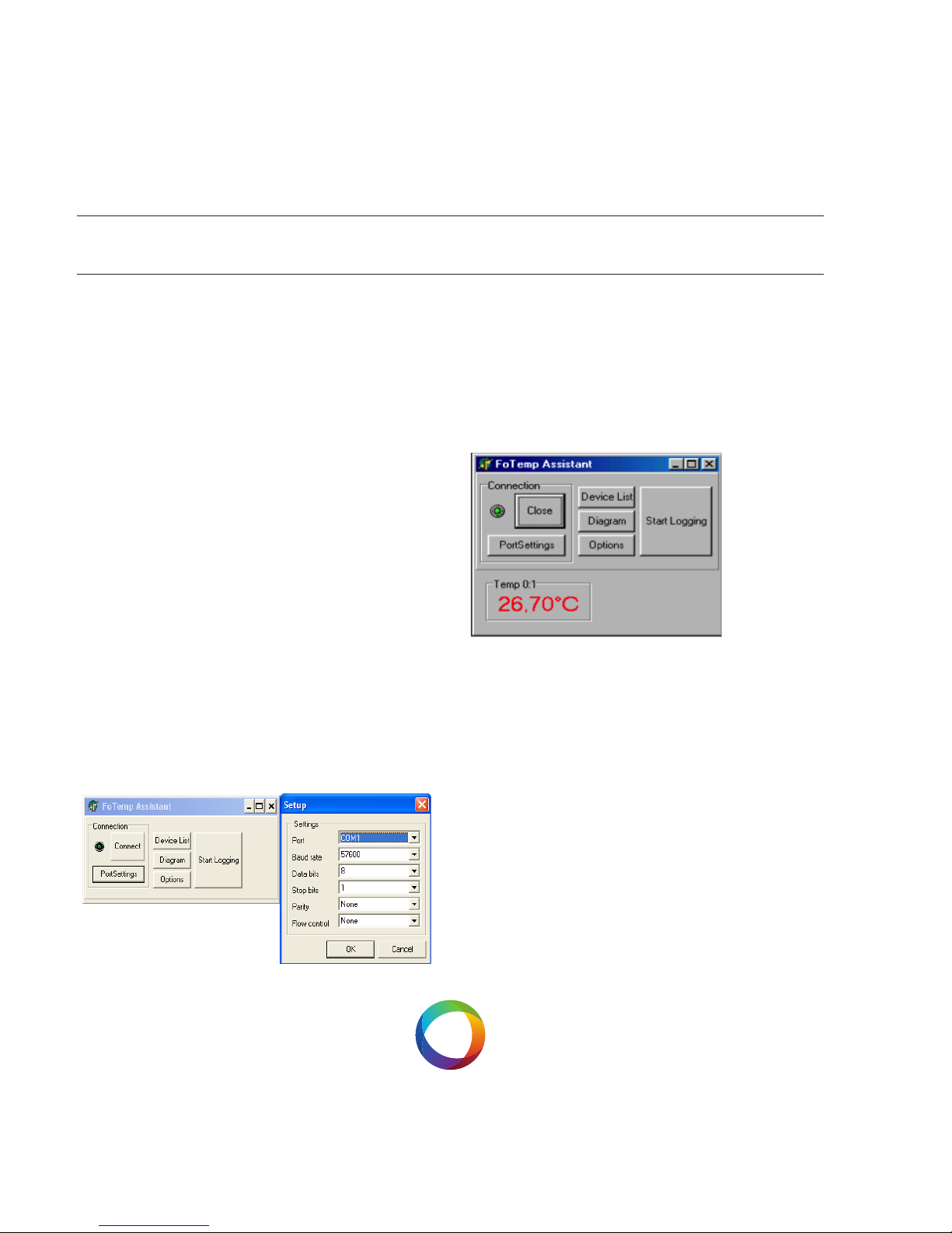
Furthermore the COM port and connection
settings should be set correctly (button
“Portsettings”), see page 22.
Press the“Connect“ button : the connected device should display a temperature value shortly.
If an error occurs during the measurement (e.g.
no sensor connected) the display will show
“Sensor?” and the LED will ash red light.
Page 21
USER MANUALFOTEMP1
21
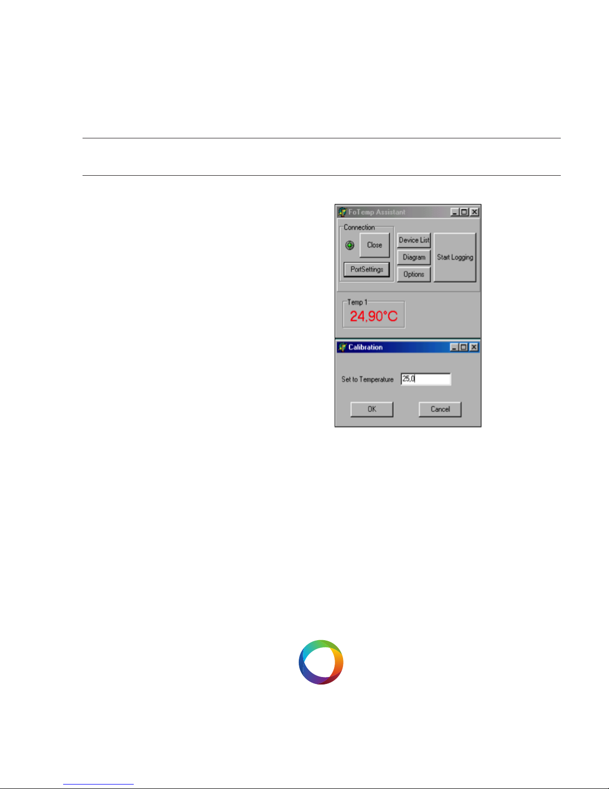
ONE POINT CALIBRATION
If a slight deviation between real and displayed
temperature is encountered, it is
possible to eliminate the temperature dierence by doing a one point calibration at a well
known temperature.
For doing so please click the right mouse
button on the temperature panel which shall
be adjusted. A context menu will appear. Please
select “one point calibration” and enter the real
temperature value and click “OK”.
The device should now display the correct
temperature.
One point calibration can be made undone at
any time selecting „reset calibration“
from the content menu.
Page 22

USER MANUALFOTEMP1
22
CONNECTING FOTEMP DEVICE WITH PC VIA USB RS232 CABLE
The driver for the converter must be properly
installed according to request. Use the included
CD:
1) Insert converter in the USB port
2) Windows 7 and 8 most of converters used
their own drivers
3) For Windows XP on request insert the CD and
select the source „CD“ in the driver manager
4) The driver installation must end with the
message that the installation was successful
and the new hardware is ready to use
5) For control you can look up in Settings /
Control Panel / System / Hardware / Device
Manager / Ports (COM & LPT).
There the converter must be as „USB Serial
Port“, „USB Serial Converter“ etc. registered and
do not equipped with error marker (yellow
question mark).
6) Here you can also read the „COM Number“,
which is necessary for future communication
with the software.
Manual parameter settings for serial interfaces
The serial port parameters must be set manually if you use some special converter types. In
that case you have to open the Device Manager
under Ports (COM & LPT) for seeing the characteristics of the converter display (double- click
the converter-entry). In the „Port Settings“ must
be set for communication with FOTEMP devices
following values:
Baud rate: 57600
Data bits: 8
Parity: None
Stop bits: 1
Flow control: None
Page 23
USER MANUALFOTEMP1
23
VIEWING TEMPERATURE DATA
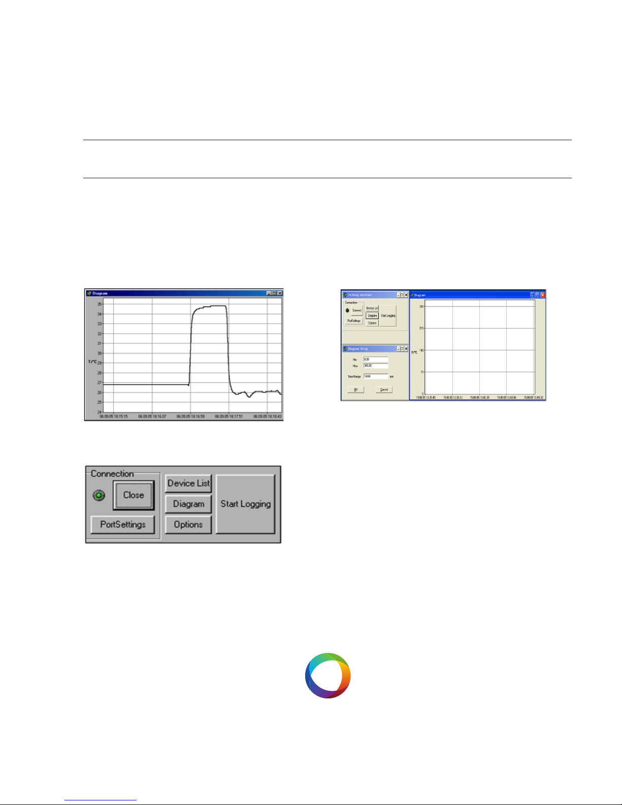
The temperatures can be displayed graphically
as a time course. The diagram window with the
temperature plot(s) may be hidden/displayed
by clicking the “Diagram“ button.
By double clicking on the diagram buttom a
window appears showing a dialog by which
the featured window can be adjusted (min/max
temperature, time range in minutes).
Page 24
USER MANUALFOTEMP1
24
ANALOG OUTPUT / LED
The device has an alanog output corresponding
to each temperature channel. They are located
beneath each ST socket as BNC socket.
The limits are set to 0°C and 300°C.
For temperatures outside of this range analog
output is set to the maximum value.
The temperatures are mapped to values
between 0-10V or 4-20mA. If no temperature
sensor is connected, the maximum value is
applied.
The maximum values for the analog output
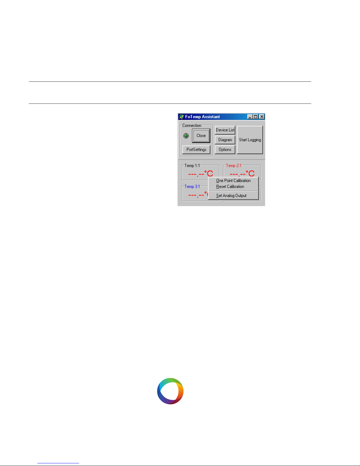
can be also set via the accompanying software
„FOTEMP-MKT“. For doing so, please make a
right mouse click and choose „Set Analog Out“,
for each channel.
LED
The LED indicates the status of each channel. In
case of damage, sensor either defective or nonexistence, the LED ashes red.
In normal operation, sensor is available, measurements are carried out, it ashes green.
Page 25
USER MANUALFOTEMP1
25
LOGGING
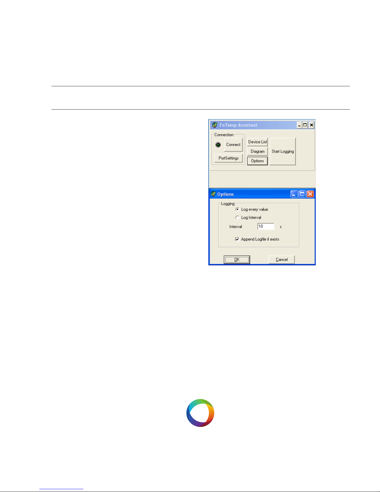
Clicking “Start Logging“ activates the logging of
the measured data. These are logged and saved
to a le that has to be specied in the appearing
dialog. The log le holds the data
formatted in columns for date/time and temperature values of all channels (one for
FOTEMP1) respectively.
By clicking ”Options“ the log interval can be
selected.
Page 26
USER MANUALFOTEMP1
26
DEVICE LIST
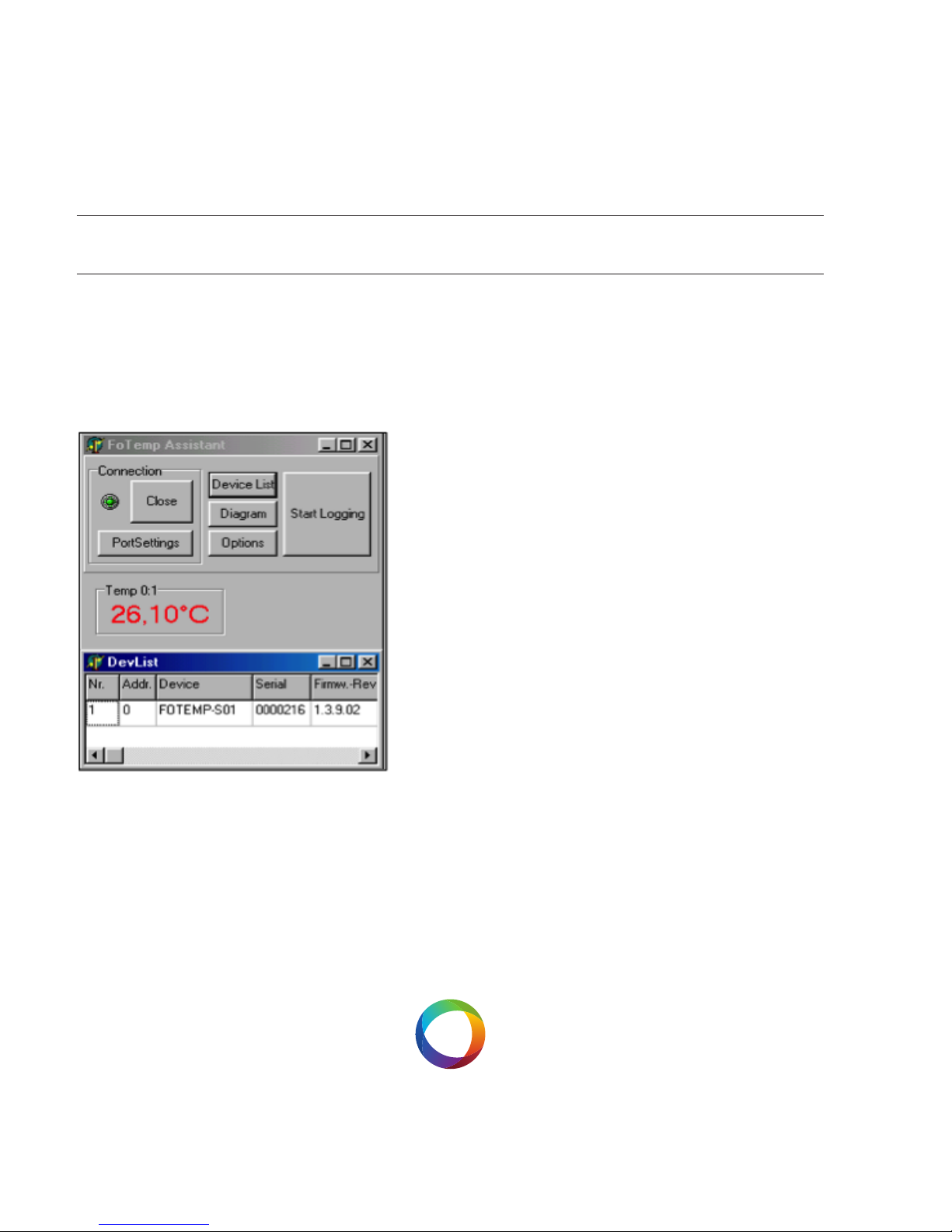
Device List: After clicking on this button a list
of all detected devices appears. There, among
other things, information on serial number and
rmware version will be displayed.
Page 27
USER MANUALFOTEMP1
27
SPEICHERN / DRUCKEN DER TEMPERATURDATEN
Under the menu item „Window“ of the graph
window, there is a choice to save the temperature prole shown as a bitmap, print the active
window contents using „Save as Bitmap“, or just
„Print“.
„Copy to clipboard“ copies the temperature
prole in the clipboard.
Export into a Windows Excel File
The log le is automatically saved and can be
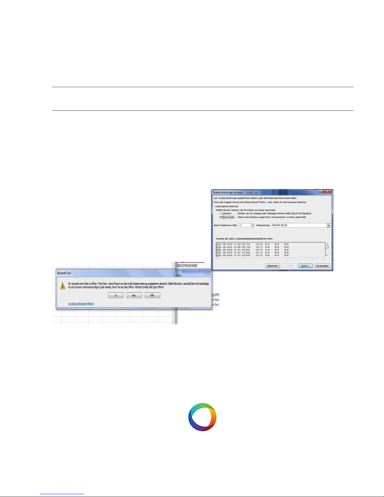
imported into Microsoft Excel 2010. This. Open
Excel, click on „File“, „Open“, select your log le,
the following message box appears:
Please press yes to open the le menu
conversion. Please tick „Fixed width“.
Then press „Finish“.
Now you can see your results in
separate elds of an Excel table.
Page 28

OPTOCON AG
OPTICAL SENSORS AND SYSTEMS
PHONE +49351 3101957
FAX +49351 3111951
POHLANDSTRASSE 17
D01309 DRESDEN
INFOOPTOCON.DE
WWW.OPTOCON.DE
© 2013 Optocon AG
Technische und inhaltliche
Änderungen ohne
Vorankündigung vorbehalten.
 Loading...