

Page 1

Optoelectronics, Inc.
OPTOCOM
Serial Interface Specification
Interface Version 1.1
May 11, 1999
Page 2

INTRODUCTION
This document describes the serial interface of the OPTOCOM, a computer-controlled VHF/UHF
Receiver. The OPTOCOM provides a serial computer interface, as well as built-in circuitry to
decode Dual-Tone Multi-Frequency (DTMF) digits, Continuous Tone-Controlled Squelch System
(CTCSS) sub-audible tones, Digitally-Coded Squelch (DCS) codes, and Logic Trunked Radio (LTR)
data. The OPTOCOM receiver, along with a personal computer and the appropriate application
software, forms a complete computer-aided scanning system capable of receiving VHF/UHF signals
in the range 25 - 520 MHz, 760 - 823.995 MHz, 849 - 868.995 MHz, and 894 - 1300 MHz. AM, FMnarrowband, and FM-wideband modes are supported.
This document was written to assist the programmer in developing software applications for the
OPTOCOM.
Optoelectronics, Inc. assumes no responsibility for the accuracy of the information contained in this
document. Optoelectronics, Inc. is under no obligation to provide technical support on matters
pertaining to this document, or to provide notification of changes or corrections to this document.
To inquire about possible revisions, or to order copies of this document, contact the factory. A
nominal fee may be charged to cover printing and shipping costs.
OPTOELECTRONICS, INC.
5821 N.E. 14th Avenue
Fort Lauderdale, FL 33334
Phone: (954) 771-2050
FAX: (954) 771-2052
Page 2 of 62
Page 3
ABOUT CI-5
The serial interface on the OPTOCOM conforms to the Icom CI-V interface standard, with
enhancements unique to Optoelectronics products. The CI-5 interface is an asynchronous, halfduplex, Transistor Transistor Logic (TTL) serial interface connected in a wire-OR (bussed)
configuration. Several different devices can be connected to the bus simultaneously, and each
device has its own unique address. Software developers are strongly encouraged to obtain a copy of
the Icom Communication Interface - V Reference Manual from Icom, Inc. for detailed information on
the CI-V interface protocol. The communications parameters for the serial interface are listed in
Table 1 below.
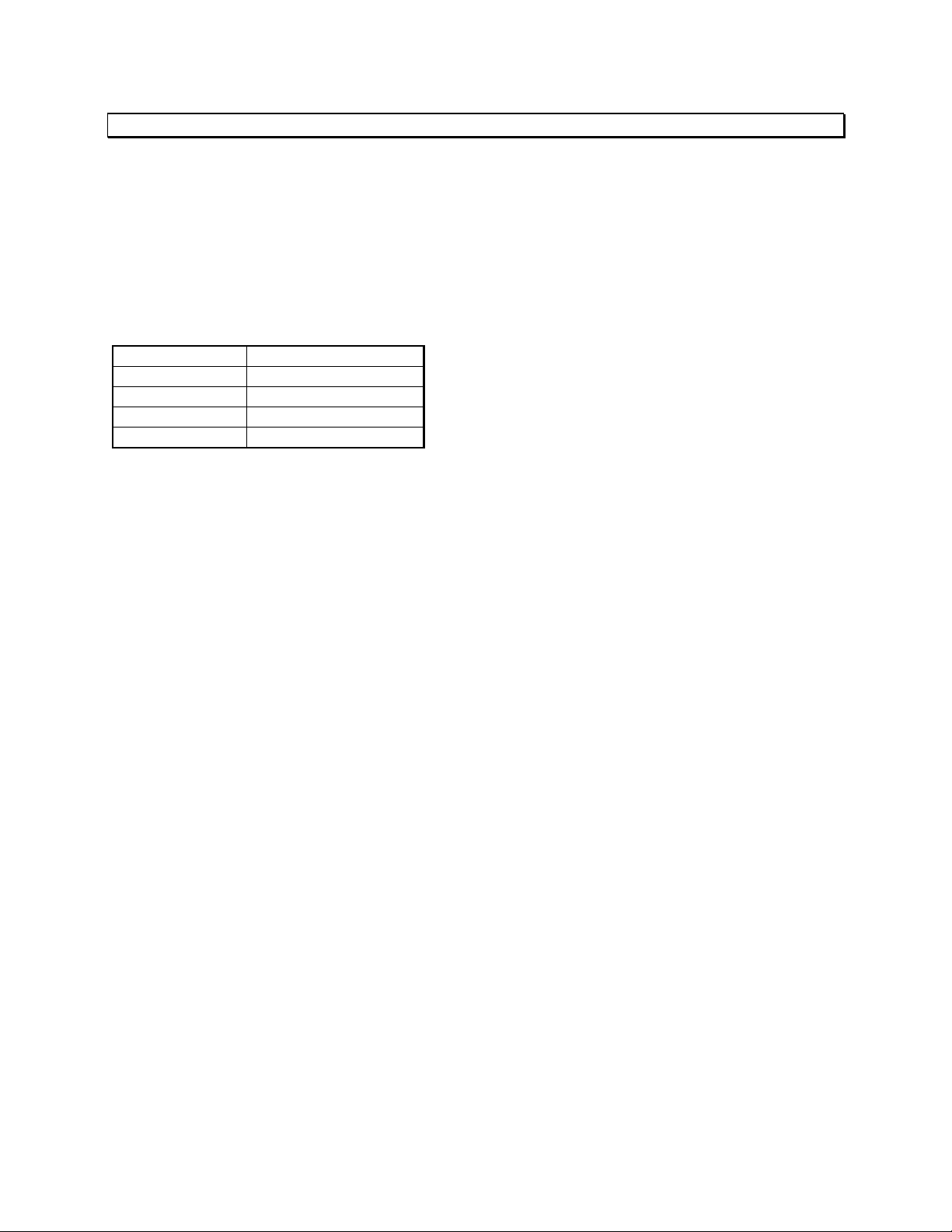
Table 1. Communications Parameters.
DATA RATE
START BITS
DATA BITS
PARITY
STOP BITS
On power up, the serial interface data rate is 9600 bps. By issuing the proper command, the data
rate can be changed. Once the data rate has been changed, the new data rate remains in effect
until it is changed again, or until the unit is powered down.
One important thing to note about the CI-5 interface is that, as mentioned above, it is connected in
a wire-OR configuration. This means that the transmit data signal and the receive data signal are
connected together. Therefore, when a command is transmitted by the computer, it is automatically
echoed back as received data, followed by the response to the command, if any. For example, if an
eleven-byte command is transmitted to a device on the bus, which returns a six-byte response, the
computer will receive a total of seventeen bytes. This configuration allows devices on the bus to
monitor their own transmissions in order to detect interface collisions. A collision occurs when two
or more devices transmit simultaneously. If a collision occurs, the command must be retransmitted.
SELECTABLE
1
8
NONE
1
The OPTOCOM includes a built-in CI-5 - to - RS-232C interface converter. Its purpose is to
convert the CI-5 interface voltage levels to RS-232C levels compatible with most personal
computers. This feature eliminates the need for an external interface converter box. The RS-232C
interface is available on the 9-pin female "D"-type connector located on the rear panel. In addition,
the RS-232C interface provides two optional interface signals, RTS and DCD, which can be used to
significantly increase the scanning speed of the OPTOCOM. These signals and their functions
are not a part of the Icom CI-V interface specification. The use of these signals is described later.
For multiple-receiver applications, such as connection of one or more OPTOCOM receivers to one
or more Icom receivers, two standard CI-5 miniature phone jacks are provided on the rear panel. In
this configuration, one or more CI-5 devices can be connected to the OPTOCOM by using one or
both of the two CI-5 jacks provided. If more than two additional devices are to be connected,
external cabling such as common 3.5mm Y-adapters can be used to connect multiple devices.
Page 3 of 62
Page 4
DTMF/CTCSS/NRZ DECODER
The OPTOCOM contains built-in circuitry to decode Dual-Tone Multi-Frequency (DTMF) digits,
Continuous Tone-Controlled Squelch System (CTCSS) sub-audible tones, and NRZ data such as
Digitally-Coded Squelch (DCS) codes, and Logic Trunked Radio (LTR) data. The
DTMF/CTCSS/NRZ decoder operates continuously. However, decoding only takes place when the
squelch is open, and CTCSS/NRZ decoding only takes place when FM-narrowband mode is selected.
The OPTOCOM is capable of decoding 16 DTMF digits. The specified maximum digit rate of the
DTMF decoder is 10 digits per second. The specific DTMF digits decoded by the OPTOCOM are
listed in Table 2 below.
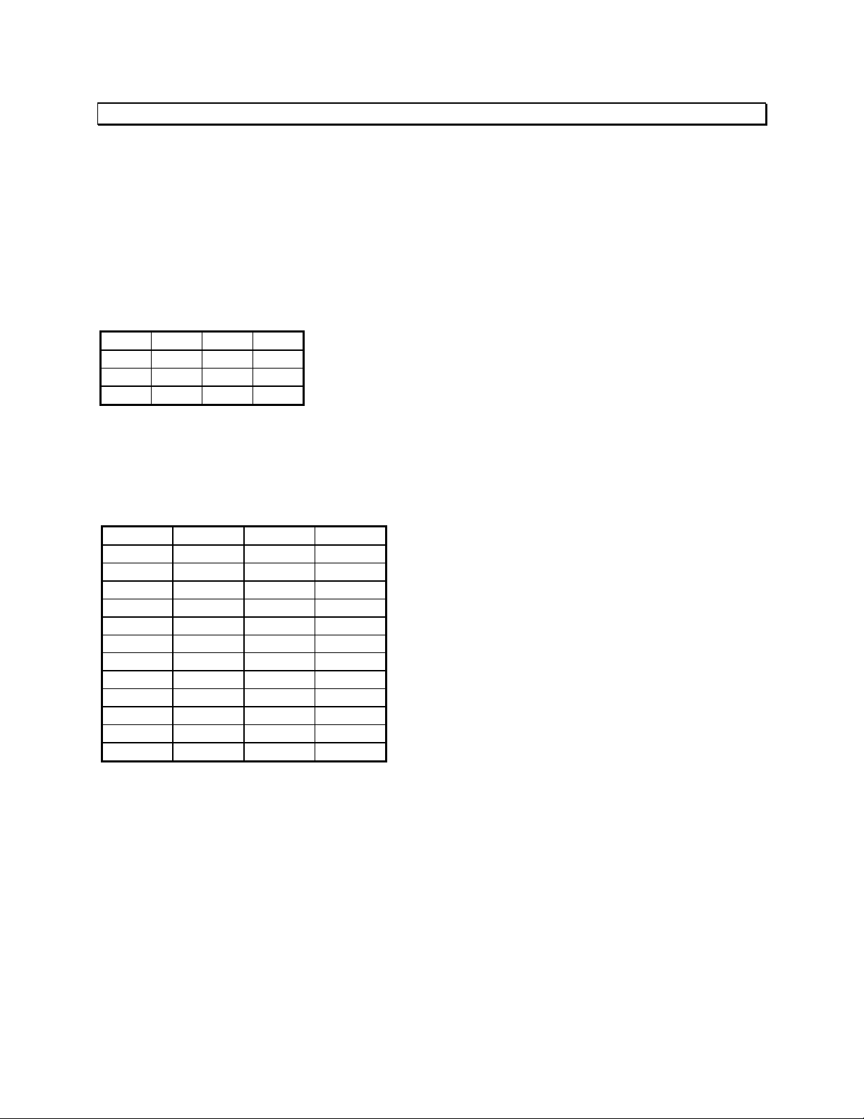
Table 2. DTMF digits.
1 2 3 A
4 5 6 B
7 8 9 C
* 0 # D
The OPTOCOM is capable of decoding 52 CTCSS tones. The specified acquisition time of the
CTCSS decoder is 200 milliseconds (0.2 seconds). At times it may be faster, or, if the incoming
signal is weak or noisy, it may be slower. The specific CTCSS tones decoded by the OPTOCOM
are listed in Table 3 below.
Table 3. CTCSS tones.
60.0 100.0 151.4 192.8
67.0 103.5 156.7 196.6
69.3 107.2 159.8 199.5
71.9 110.9 162.2 203.5
74.4 114.8 165.5 206.5
77.0 118.8 167.9 210.7
79.7 120.0 171.3 218.1
82.5 123.0 173.8 225.7
85.4 127.3 177.3 229.1
88.5 131.8 179.9 233.6
91.5 136.5 183.5 241.8
94.8 141.3 186.2 250.3
97.4 146.2 189.9 254.1
Page 4 of 62
Page 5

The OPTOCOM is capable of decoding 106 DCS codes. The specified acquisition time of the DCS
decoder is 350 milliseconds (0.35 seconds). At times it may be faster, or, if the incoming signal is
weak or noisy, it may be slower. The specific DCS codes decoded by the OPTOCOM are listed in
Table 4 below.
Table 4. DCS codes.
017 125 251 411 565
023 131 252 412 606
025 132 255 413 612
026 134 261 423 624
031 143 263 431 627
032 145 265 432 631
036 152 266 445 632
043 155 271 446 654
047 156 274 452 662
050 162 306 454 664
051 165 311 455 703
053 172 315 462 712
054 174 325 464 723
065 205 331 465 731
071 212 332 466 732
072 223 343 503 734
073 225 346 506 743
074 226 351 516 754
114 243 356 523
115 244 364 526
116 245 365 532
122 246 371 546
Page 5 of 62
Page 6

PIPELINED TUNING
Perhaps the most significant feature of the OPTOCOM is its ability to pipeline the tuning
operation. This is important because it significantly increases the maximum possible scanning
speed of the receiver. By making use of this feature, scanning speeds of up to 80 channels per
second are possible.
In non-pipelined computer-aided scanning systems, scanning each frequency involves three main
steps performed in sequence. First, the command or commands to tune the receiver to the new
frequency and/or mode must be issued. The amount of time required by this step depends on the
number of bytes in the command or commands and their responses, and the serial interface data
rate.
The second step involves the settling time of the receiver, once the new frequency and/or mode
command or commands have been received. The receiver settling time includes the time necessary
for the synthesizers to slew and re-acquire lock, the time necessary for the preselector filters to
settle, and the time necessary for the squelch detection circuitry to respond. The settling time of
the OPTOCOM receiver is 12 milliseconds (0.012 seconds) maximum.
Third, the command to request squelch status must be issued and the response returned. The
amount of time required by this step is again dependent on the length of the command and its
response, and the serial interface data rate.
To increase scanning speed, the overall time required for the three steps outlined above must be
reduced. Receiver settling time is generally a function of the hardware architecture. Therefore,
nothing much can be done to reduce the settling time, short of a fairly major re-design of the
receiver hardware. The remaining area of concern is the transit time of commands and responses
on the serial interface.
One obvious way to reduce the serial interface transit time is to simply increase the data rate.
However, even at 19,200 bps, the practical limit of many PC-based serial ports, the collective transit
time of the necessary commands and responses is several milliseconds.
The most desirable solution is to completely eliminate the serial interface transit time from
impacting the scanning speed. This can be accomplished by the use of pipelining. The basic concept
of the OPTOCOM pipelined tuning scheme is to take advantage of the otherwise wasted receiver
settling time by sending the next frequency and mode to the receiver while it is still settling on the
current frequency and mode. A special command, TRANSFER NEXT FREQUENCY/MODE, is
provided in which the next frequency and mode are sent to the receiver, but do not take effect until
commanded to do so. Therefore, the transit time of the command is totally transparent, as long as it
is completed within the settling time of the receiver. This can be easily accomplished at an
interface data rate of 19,200 bps. In fact, there is no advantage to increasing the data rate beyond
19,200 bps, since the limiting factor is the 12 millisecond receiver settling time.
To complete the operation, two hardware interface signals are added. First, the Request To Send
(RTS) RS-232C interface signal is used as a hardware tuning command. Once the next frequency
and mode have been sent to the receiver using the TRANSFER NEXT FREQUENCY/MODE
command, the receiver is commanded to tune to the next frequency and mode by simply changing
the state of the RTS signal. If it was previously negated, it is asserted. If it was previously
asserted, it is negated. The receiver immediately begins settling on the next frequency and mode,
which have now become the current frequency and mode.
Page 6 of 62
Page 7
Second, the Data Carrier Detect (DCD) RS-232C interface signal is used as a hardware squelch
indicator. This eliminates the need to send a command over the serial interface to request squelch
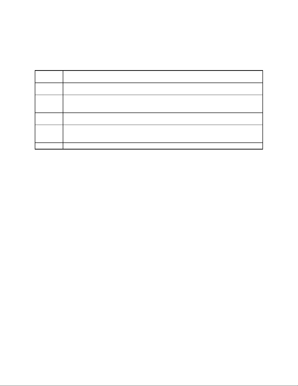
status, and wait for the response. The steps involved in implementing a fully pipelined computeraided scanning system are summarized in Table 5 below.
Table 5. Pipelined Tuning Sequence.
Step 1:
Step 2:
Step 3:
Step 4:
Step 5:
Step 6:
Of course, either of the two hardware interface signals can be used without the other, but maximum
scanning speed is achieved when both are used. It should be noted that the implementation of the
RTS and DCD interface signals by the OPTOCOM is not a part of the Icom CI-V interface
specification, which specifies only the serial interface protocol. If more than one OPTOCOM
receiver is connected on the bus, then special hardware provisions must be made to provide RTS
and DCD signals for each receiver. However, the details are beyond the scope of this specification.
Alternatively, the appropriate serial interface commands can be used in place of the two hardware
signals, but maximum scanning speed will be degraded.
Send the next frequency and mode to the receiver using the TRANSFER NEXT
FREQUENCY/MODE command.
Change the state of the RTS interface signal to cause the next frequency and mode to
become the current frequency and mode, and the receiver to begin settling.
While the receiver is still settling on the current frequency and mode, send the next
frequency and mode to the receiver using the TRANSFER NEXT
FREQUENCY/MODE command.
Wait for the receiver to finish settling. The total settling time, including sending the
next frequency and mode, is 12 milliseconds (0.012 seconds).
Check the squelch status by reading the DCD interface signal. If the squelch is open,
scanning is stopped. Otherwise, scanning continues. Optionally, the status of the
DTMF/CTCSS/NRZ decoder can be checked, and the appropriate action taken.
Continuously repeat steps 2 through 5 above.
Page 7 of 62
Page 8

BitBanger MODE
BitBanger mode is a special mode in which the OptoCom processor inputs raw data from the onboard data slicer at a selected data rate. The data is then transmitted to the host computer via the
CI-5 port at the CI-5 interface data rate, 1 byte at a time.
To use BitBanger mode, the host computer must first select the desired data rate at which data is
to be received from the data slicer. This is accomplished using the WRITE BIT BANGER DATA
RATE command. BitBanger mode is then enabled using the WRITE BIT BANGER MODE
command. Once enabled, BitBanger mode is activated or deactivated by asserting or negating the
DTR serial interface signal, respectively. When BitBanger mode is enabled and activated, all
normal CI-5 operation ceases, and raw data received from the data slicer is transmitted
continuously to the host computer via the serial port. When the host computer has finished
receiving data from the data slicer, normal CI-5 functionality can be restored by negating the DTR
serial interface signal, and/or disabling BitBanger mode. When BitBanger mode is disabled (the
power-up default state), the DTR serial interface signal is ignored.
It is important to note that no CI-5 commands or responses can be exchanged while BitBanger
mode is enabled and activated. Therefore, the burden is on the host computer software to ensure
that any CI-5 activity in progress is complete before activating BitBanger mode. For example, if a
CI-5 command has been issued, the host computer should wait until the response is received before
activating BitBanger mode.
It is also important to note that data received from the data slicer at the BitBanger data rate is
transmitted to the host computer at the CI-5 interface data rate with no flow control. Therefore, the
host computer software must ensure that the CI-5 interface data rate is sufficient to handle the
selected BitBanger data rate. For example, if 3600 bps is chosen as the BitBanger data rate,
then the power-up default CI-5 interface data rate of 9600 bps will be sufficient to keep up with the
incoming data. However, if 9600 bps is chosen as the BitBanger data rate, then the CI-5 interface
data rate should be changed to at least 19,200 bps to ensure that data overflow does not occur.
Page 8 of 62
Page 9

COMMAND REFERENCE
The OPTOCOM recognizes 43 different commands. The first 9 commands are standard Icom CI-V
commands compatible with receivers such as the Icom R-7100. The remaining "7F" series
commands are special OPTOCOM commands provided to access features, such as
DTMF/CTCSS/NRZ decoding, not generally found on other receivers. The commands, along with
their corresponding responses, are summarized in Table 6 below.
Following the table is a detailed description of each of the commands, including examples
illustrating their use. In the command descriptions, "ra" refers to the RECEIVE ADDRESS, and
"ta" refers to the TRANSMIT ADDRESS.
The RECEIVE ADDRESS is the address of the OPTOCOM, which can be any address in the
range 80 through 8F. Each device on the CI-5 bus must have its own unique address. The
OPTOCOM will not process any command in which the RECEIVE ADDRESS does not match its
own currently selected address. However, the OPTOCOM will process commands with a
RECEIVE ADDRESS of 00, but all command responses will be suppressed. A RECEIVE ADDRESS
of 00 has special meaning. It provides a means for a device on the CI-5 bus to transmit a command
to all other devices simultaneously. However, since several simultaneous responses would cause a
collision, the responses are suppressed.
The TRANSMIT ADDRESS is the address of the device which is transmitting the command to the
OPTOCOM. In most cases, this device is a personal computer executing application software,
usually referred to as the CONTROLLER. The standard address for the CONTROLLER is E0, but
any address can be used for the TRANSMIT ADDRESS. However, the TRANSMIT ADDRESS must
be in the range 01 to EF. Also, the OPTOCOM will not process any command in which the
TRANSMIT ADDRESS matches its own currently selected address.
It is important to remember that the values specified are not ASCII characters, but are bytes
expressed in hexadecimal notation. For example, “FE” represents a single byte with a value of
0xFE (hexadecimal), or 254 (decimal). It does not represent the ASCII character “F” followed by the
ASCII character “E”, a two-byte sequence.
Page 9 of 62
Page 10

Table 6. OPTOCOM CI-5 Interface Command Summary.
COMMAND SUB-COMMAND DESCRIPTION
00 - Transfer frequency, no response.
01 - Transfer mode, no response.
02 - Read upper/lower-edge frequency.
03 - Read frequency.
04 - Read mode.
05 - Write frequency.
06 - Write mode.
15 01 Read squelch status.
15 02 Read signal strength.
7F 01 Select LOCAL control (OS535 emulation)
7F 02 Select REMOTE control (OS535 emulation)
7F 03 Enable tape recorder.
7F 04 Disable tape recorder.
7F 05 Read status.
7F 06 Read CTCSS tone.
7F 07 Read DCS code.
7F 08 Read DTMF digit.
7F 09 Read identification
7F 0A Enable speaker audio.
7F 0B Disable speaker audio.
7F 0C Enable 5 kHz search window.
7F 0D Disable 5 kHz search window.
7F 0E Transfer next frequency/mode, no response.
7F 0F Enable search mode.
7F 10 Disable search mode.
7F 11 Write decode mode
7F 12 Read LTR data
7F 13 Write volume/squelch control
7F 14 Read volume setting
7F 15 Write volume setting
7F 16 Read squelch setting
7F 17 Write squelch setting
7F 18 Write scan mode
7F 19 Read memory
7F 1A Write memory
7F 1B Clear memory
7F 1C Write Bit Banger Data Rate
7F 1D Write Bit Banger Mode
7F D0 Write CI-5 address
7F D1 Write CI-5 data rate
7F D2 Write CI-5 interface mode
7F D3 Store operating parameters
7F D4 Recall operating parameters
Page 10 of 62
Page 11

TRANSFER FREQUENCY
Command:
FE FE ra ta 00 frequency FD
Example:
437.162500 MHz
FE FE 80 E0 00 00 25 16 37 04 FD
Response:
NONE
Description:
This command selects the operating frequency of the receiver. However, no response is returned
under any condition.
The frequency data is in the form of 5 bytes, each consisting of 2 BCD digits. The order of the 10
BCD digits is as follows: 10 Hz digit, 1 Hz digit, 1 kHz digit, 100 Hz digit, 100 kHz digit, 10 kHz
digit, 10 MHz digit, 1 MHz digit, 1 GHz digit, 100 MHz digit. See the example shown above.
If SCAN mode is enabled, then the frequency change is not processed immediately, but is saved to
take effect later when SCAN mode is disabled.
If the command length is incorrect, or if the received frequency is not in the range 25 - 520 MHz,
760 - 823.995 MHz, 849 - 868.995 MHz, or 894 - 1300 MHz, or is not an even multiple of 5 kHz or
12.5 kHz, then the command is ignored.
Page 11 of 62
Page 12
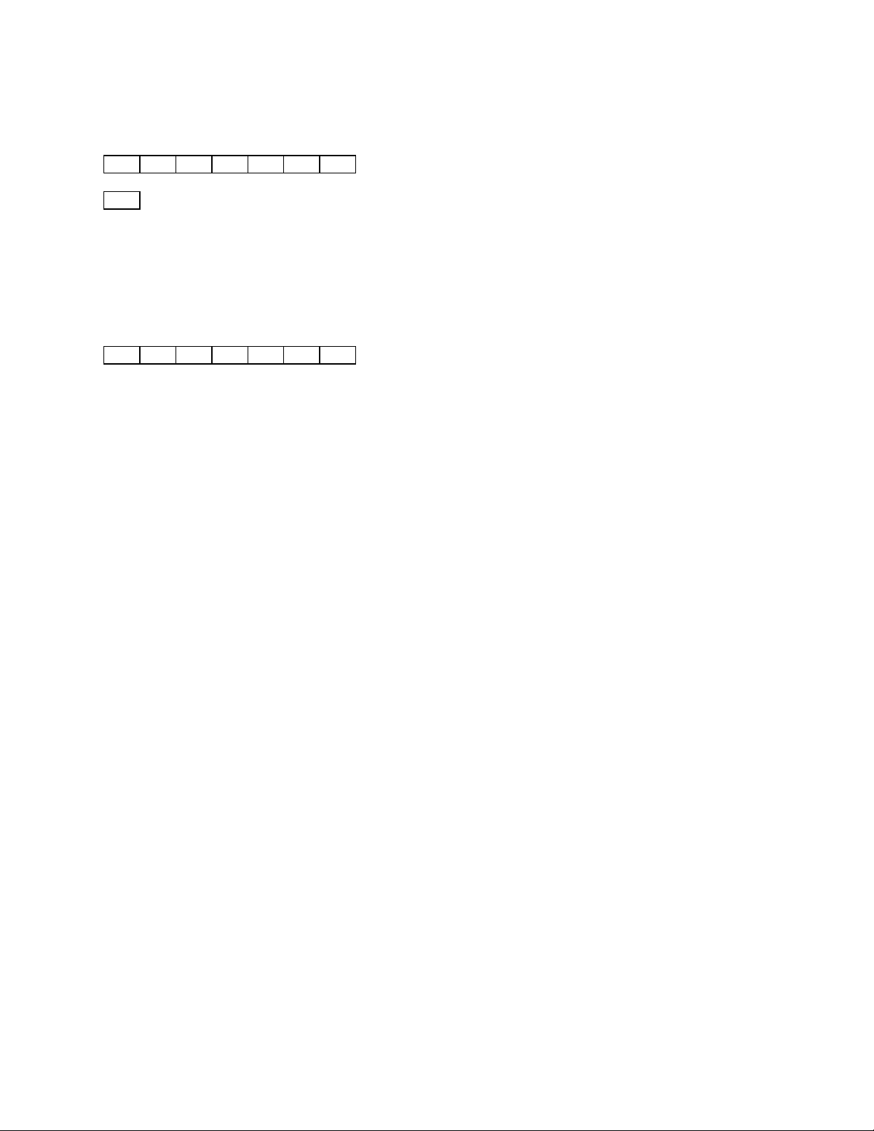
TRANSFER MODE
Command:
FE FE ra ta 01 md FD
is a BCD value representing the desired operating mode. BCD values are encoded as
md
follows:
02: AM
05: FM-narrowband
06: FM-wideband
Example:
FM-narrowband
FE FE 80 E0 01 05 FD
Response:
NONE
Description:
This command selects the operating mode of the receiver. However, no response is returned under
any condition.
The mode data is in the form of 1 byte, consisting of 2 BCD digits. See the example shown above.
If SCAN mode is enabled, then the mode change is not processed immediately, but is saved to take
effect later when SCAN mode is disabled.
If the command length is incorrect, or if the received mode data is not valid, then the command is
ignored.
Page 12 of 62
Page 13
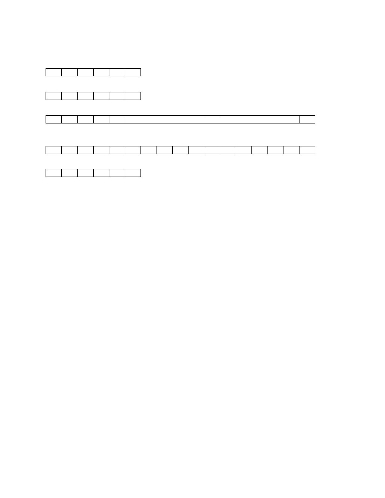
READ UPPER/LOWER-EDGE FREQUENCY
Command:
FE FE ra ta 02 FD
Example:
FE FE 80 E0 02 FD
Response:
FE FE ta ra 02 lower frequency 2D upper frequency FD
Examples:
25.000000 - 1300.000000 MHz
FE FE E0 80 02 00 00 00 25 00 2D 00 00 00 00 13 FD
Error
FE FE E0 80 FA FD
Description:
This command instructs the unit to send the upper and lower edge of the operating frequency
range.
The frequency data is in the form of 5 bytes, each consisting of 2 BCD digits. The order of the 10
BCD digits is as follows: 10 Hz digit, 1 Hz digit, 1 kHz digit, 100 Hz digit, 100 kHz digit, 10 kHz
digit, 10 MHz digit, 1 MHz digit, 1 GHz digit, 100 MHz digit. See the example shown above.
If the command length is incorrect, then the command is ignored, and the error response is
returned.
Page 13 of 62
Page 14
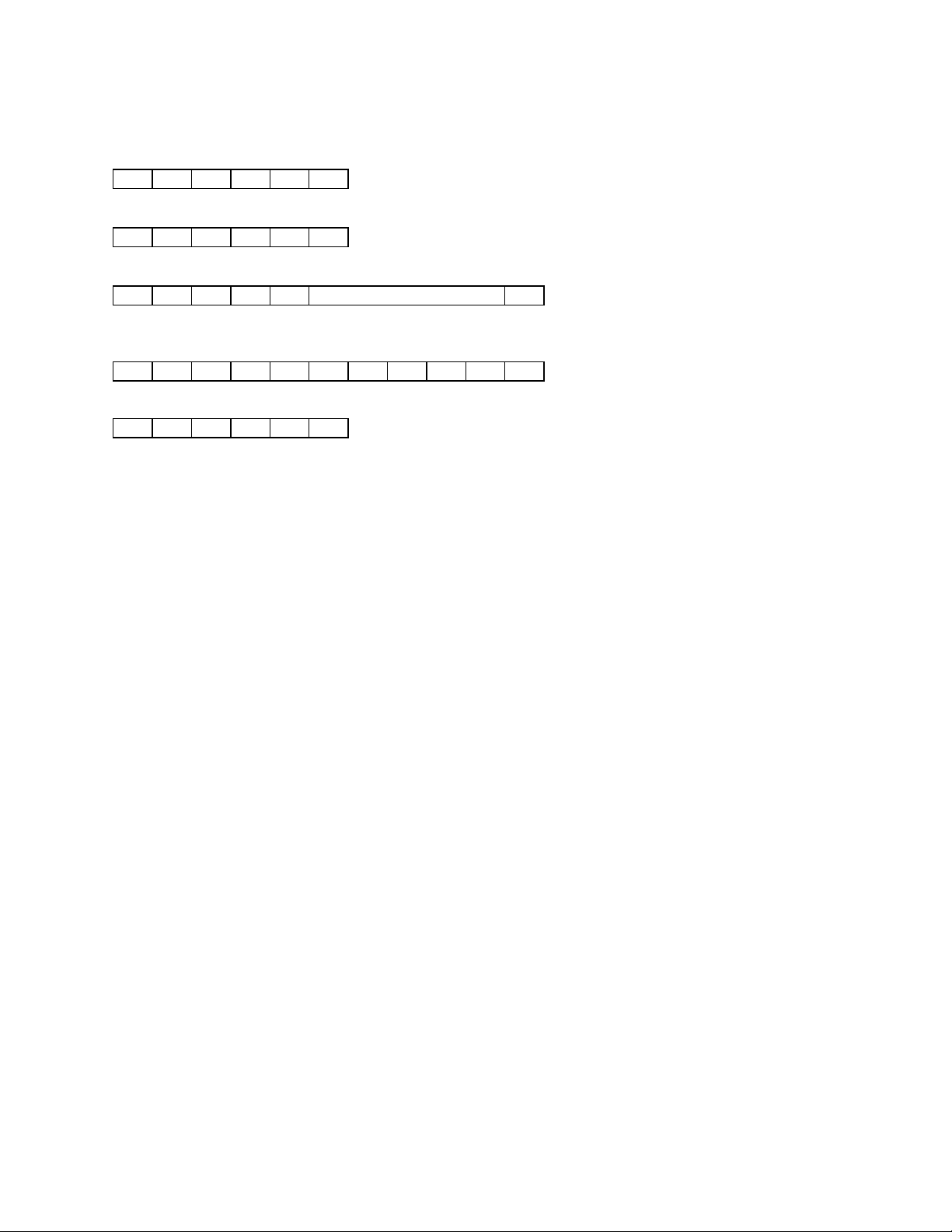
READ FREQUENCY
Command:
FE FE ra ta 03 FD
Example:
FE FE 80 E0 03 FD
Response:
FE FE ta ra 03 frequency FD
Examples:
162.550000 MHz
FE FE E0 80 03 00 00 55 62 01 FD
Error
FE FE E0 80 FA FD
Description:
This command instructs the unit to send the current operating frequency.
The frequency data is in the form of 5 bytes, each consisting of 2 BCD digits. The order of the 10
BCD digits is as follows: 10 Hz digit, 1 Hz digit, 1 kHz digit, 100 Hz digit, 100 kHz digit, 10 kHz
digit, 10 MHz digit, 1 MHz digit, 1 GHz digit, 100 MHz digit. See the example shown above.
If the command length is incorrect, then the command is ignored, and the error response is
returned.
Page 14 of 62
Page 15
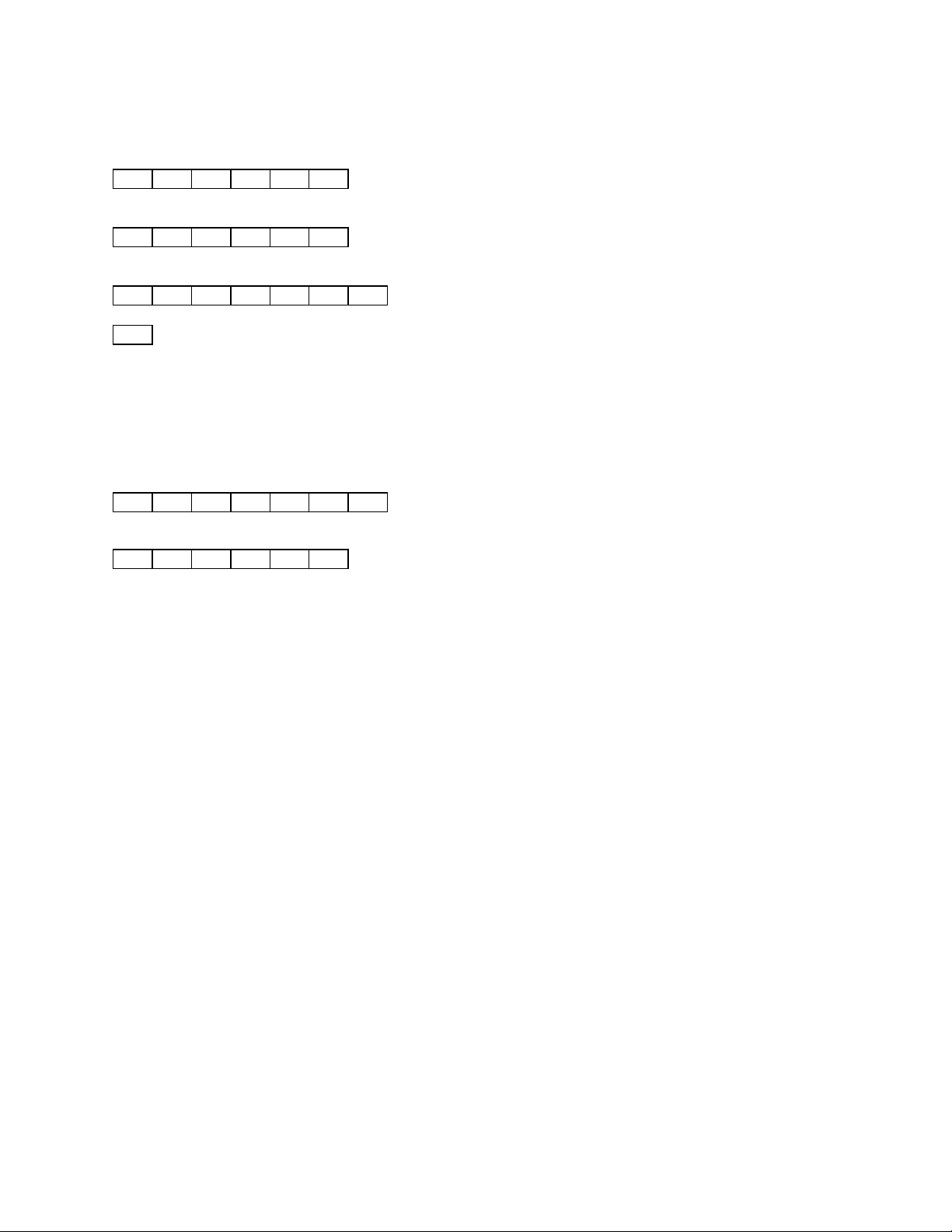
READ MODE
Command:
FE FE ra ta 04 FD
Example:
FE FE 80 E0 04 FD
Response:
FE FE ta ra 04 md FD
is a BCD value representing the currently selected operating mode. BCD values are
md
encoded as follows:
02: AM
05: FM-narrowband
06: FM-wideband
Examples:
AM
FE FE E0 80 04 02 FD
Error
FE FE E0 80 FA FD
Description:
This command instructs the unit to send the current operating mode.
The mode data is in the form of 1 byte, consisting of 2 BCD digits. See the example shown above.
If the command length is incorrect, then the command is ignored, and the error response is
returned.
Page 15 of 62
Page 16
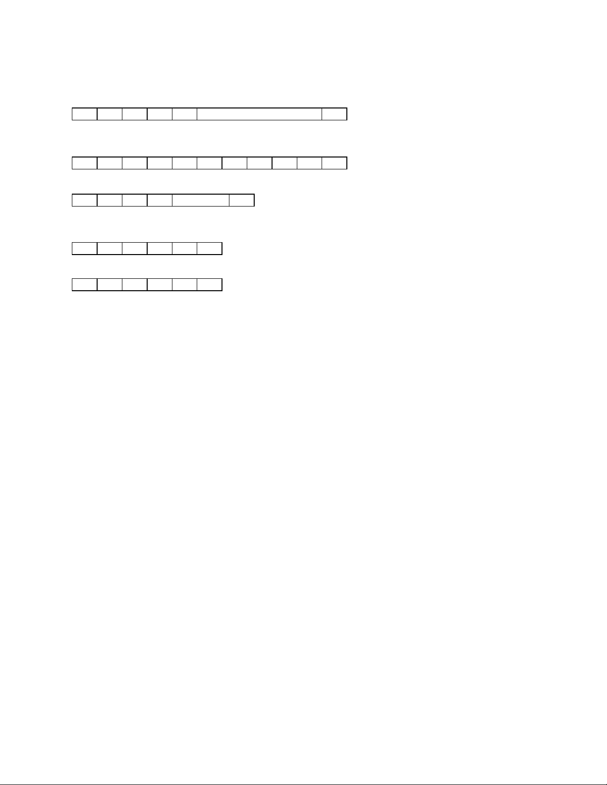
WRITE FREQUENCY
Command:
FE FE ra ta 05 frequency FD
Example:
162.550000 MHz
FE FE 80 E0 05 00 00 55 62 01 FD
Response:
FE FE ta ra FB or FA FD
Examples:
OK
FE FE E0 80 FB FD
Error
FE FE E0 80 FA FD
Description:
This command selects the operating frequency of the receiver.
The frequency data is in the form of 5 bytes, each consisting of 2 BCD digits. The order of the 10
BCD digits is as follows: 10 Hz digit, 1 Hz digit, 1 kHz digit, 100 Hz digit, 100 kHz digit, 10 kHz
digit, 10 MHz digit, 1 MHz digit, 1 GHz digit, 100 MHz digit. See the example shown above.
If SCAN mode is enabled, then the frequency change is not processed immediately, but is saved to
take effect later when SCAN mode is disabled.
If the command length is incorrect, or if the received frequency is not in the range 25 - 520 MHz,
760 - 823.995 MHz, 849 - 868.995 MHz, or 894 - 1300 MHz, or is not an even multiple of 5 kHz or
12.5 kHz, then the command is ignored, and the error response is returned.
Page 16 of 62
Page 17
WRITE MODE
Command:
FE FE ra ta 06 md FD
is a BCD value representing the desired operating mode. BCD values are encoded as
md
follows:
02: AM
05: FM-narrowband
06: FM-wideband
Example:
FM-wideband
FE FE 80 E0 06 06 FD
Response:
FE FE ta ra FB or FA FD
Examples:
OK
FE FE E0 80 FB FD
Error
FE FE E0 80 FA FD
Description:
This command selects the operating mode of the receiver.
The mode data is in the form of 1 byte, consisting of 2 BCD digits. See the example shown above.
If SCAN mode is enabled, then the mode change is not processed immediately, but is saved to take
effect later when SCAN mode is disabled.
If the command length is incorrect, or if the received mode data is not valid, then the command is
ignored, and the error response is returned.
Page 17 of 62
Page 18
READ SQUELCH STATUS
Command:
FE FE ra ta 15 01 FD
Example:
FE FE 80 E0 15 01 FD
Response:
FE FE ta ra 15 01 sd FD
Examples:
Squelch closed
FE FE E0 80 15 01 00 FD
Squelch open
FE FE E0 80 15 01 01 FD
Error
FE FE E0 80 FA FD
Description:
This command instructs the unit to send the current squelch status.
The squelch status data is in the form of 1 byte, consisting of 2 BCD digits. See the examples shown
above.
If the command length is incorrect, then the command is ignored, and the error response is
returned.
Page 18 of 62
Page 19
READ SIGNAL STRENGTH
Command:
FE FE ra ta 15 02 FD
Example:
FE FE 80 E0 15 02 FD
Response:
FE FE ta ra 15 02 sd FD
Examples:
- 20 dBm
FE FE E0 80 15 02 00 20 FD
- 67 dBm
FE FE E0 80 15 02 00 67 FD
- 137 dBm
FE FE E0 80 15 02 01 37 FD
Error
FE FE E0 80 FA FD
Description:
This command instructs the unit to send the current signal strength.
The signal strength data is in the form of 2 bytes, each consisting of 2 BCD digits. The signal
strength is reported in units of absolute dBm as measured at the antenna connector. The reported
signal strength ranges from a maximum signal of - 20 dBm to a minimum signal of - 137 dBm. A
minus sign is implied. See the examples shown above.
If the command length is incorrect, then the command is ignored, and the error response is
returned.
Page 19 of 62
Page 20
SELECT LOCAL CONTROL
Command:
FE FE ra ta 7F 01 FD
Example:
FE FE 80 E0 7F 01 FD
Response:
FE FE ta ra FB or FA FD
Examples:
OK
FE FE E0 80 FB FD
Error
FE FE E0 80 FA FD
Description:
This command selects LOCAL control. However, this command is only valid when OptoScan535
emulation mode is enabled.
This command provides no function, other than OptoScan535 emulation, which provides
backward compatibility with legacy software written for the OptoScan535. OptoScan535
emulation mode is enabled and disabled by use of the WRITE CI-5 INTERFACE MODE command.
If the command length is incorrect, then the command is ignored, and the error response is
returned.
Page 20 of 62
Page 21
SELECT REMOTE CONTROL
Command:
FE FE ra ta 7F 02 FD
Example:
FE FE 80 E0 7F 02 FD
Response:
FE FE ta ra FB or FA FD
Examples:
OK
FE FE E0 80 FB FD
Error
FE FE E0 80 FA FD
Description:
This command selects REMOTE control. However, this command is only valid when
OptoScan535 emulation mode is enabled.
This command provides no function, other than OptoScan535 emulation, which provides
backward compatibility with legacy software written for the OptoScan535. OptoScan535
emulation mode is enabled and disabled by use of the WRITE CI-5 INTERFACE MODE command.
If the command length is incorrect, then the command is ignored, and the error response is
returned.
Page 21 of 62
Page 22
ENABLE TAPE RECORDER
Command:
FE FE ra ta 7F 03 FD
Example:
FE FE 80 E0 7F 03 FD
Response:
FE FE ta ra FB or FA FD
Examples:
OK
FE FE E0 80 FB FD
Error
FE FE E0 80 FA FD
Description:
This command enables a tape recorder connected to the TAPE PAUSE output.
The TAPE PAUSE output provides a pair of isolated relay contacts which are closed when the tape
recorder is enabled, and open when the tape recorder is disabled.
If the command length is incorrect, then the command is ignored, and the error response is
returned.
Page 22 of 62
Page 23
DISABLE TAPE RECORDER
Command:
FE FE ra ta 7F 04 FD
Example:
FE FE 80 E0 7F 04 FD
Response:
FE FE ta ra FB or FA FD
Examples:
OK
FE FE E0 80 FB FD
Error
FE FE E0 80 FA FD
Description:
This command disables a tape recorder connected to the TAPE PAUSE output.
The TAPE PAUSE output provides a pair of isolated relay contacts which are closed when the tape
recorder is enabled, and open when the tape recorder is disabled.
If the command length is incorrect, then the command is ignored, and the error response is
returned.
Page 23 of 62
Page 24
READ STATUS
Command:
FE FE ra ta 7F 05 FD
Example:
FE FE 80 E0 7F 05 FD
Response:
FE FE ta ra 7F 05 s1 s2 s3 s4 FD
Examples:
LTR decoding, DTMF digit pending, squelch open, LTR data active, Audio enabled, Audio present
FE FE E0 80 7F 05 53 12 00 00 FD
LTR decoding, DTMF digit pending, squelch open, LTR data active, Audio enabled, Audio present
FE FE E0 80 7F 05 53 12 00 00 FD
Error
FE FE E0 80 FA FD
Description:
This command instructs the unit to send the current operating status.
It should be noted that when OptoScan535 emulation mode is enabled, the status data conforms
to the OptoScan535 format, instead of the format described in this document. This provides
backward compatibility with legacy software written for the OptoScan535. OptoScan535
emulation mode is enabled and disabled by use of the WRITE CI-5 INTERFACE MODE command.
The status data is in the form of 4 bytes, each consisting of 6 status bits and 2 unused bits which are
always cleared. The unused bits ensure that the status data always appears as valid BCD digits.
See the examples shown above.
If the command length is incorrect, then the command is ignored, and the error response is
returned.
The current operating status contains all pertinent information about the receiver and
DTMF/CTCSS/NRZ decoder, including squelch status. Therefore, the READ SQUELCH STATUS
command is optional. The following is a discussion of the use of the status bits contained in the
READ STATUS command. Note that the DTMF/CTCSS/NRZ decoder is only enabled when the
squelch is open, and the CTCSS/NRZ decoder is only enabled when narrowband FM mode is
selected. Therefore, the appropriate status bits should be checked frequently while the squelch is
open.
Page 24 of 62
Page 25
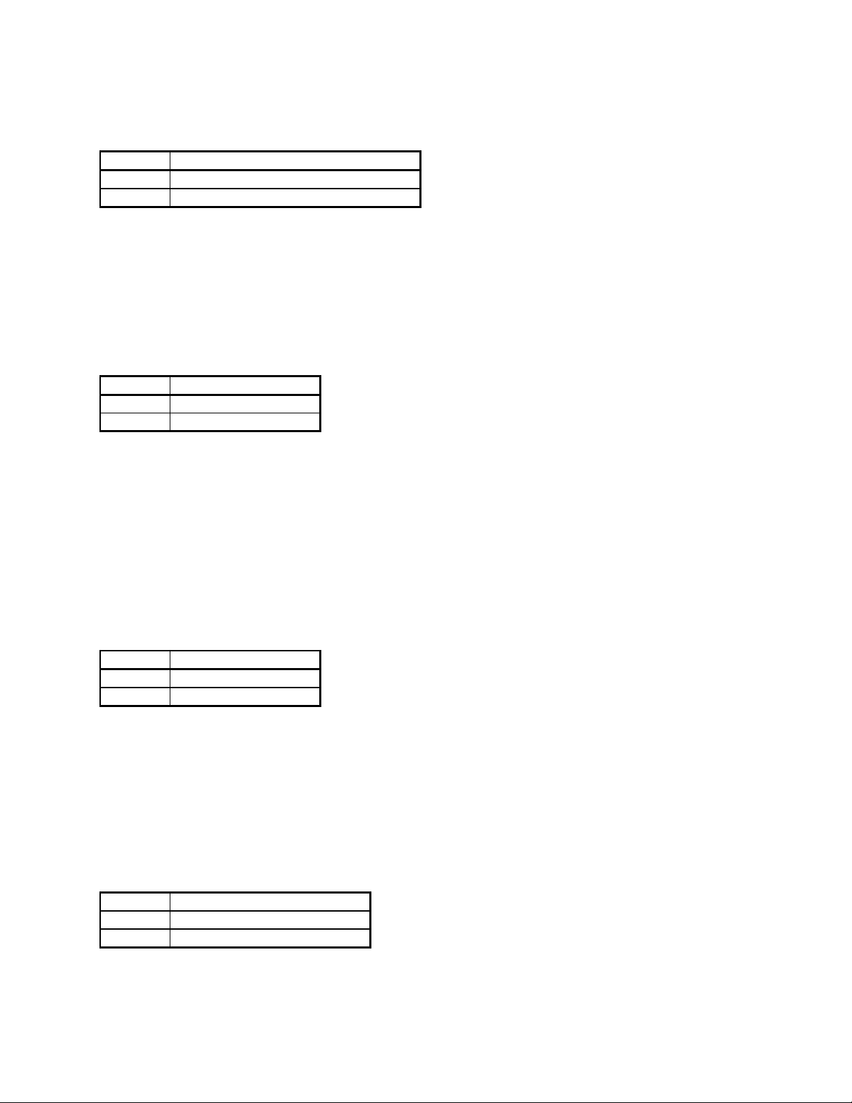
s1, bit 0: VOLUME/SQUELCH CONTROL. This bit indicates the current volume/squelch
control status. The volume/squelch control status is encoded as follows:
s1, bit 0 VOLUME/SQUELCH CONTROL
0 LOCAL
1 REMOTE
When LOCAL volume/squelch control is selected, the volume and squelch settings are controlled by
the front panel VOLUME and SQUELCH controls. When REMOTE volume/squelch control is
selected, the volume is controlled by the WRITE VOLUME SETTING command, the squelch is
controlled by the WRITE SQUELCH SETTING command, and the front panel VOLUME and
SQUELCH controls are ignored.
s1, bit 1: DTMF PENDING. This bit indicates whether or not one or more DTMF digits are
waiting in the 31-digit DTMF buffer. The DTMF buffer status is encoded as follows:
s1, bit 1 DTMF
0 BUFFER EMPTY
1 PENDING
If the DTMF PENDING bit is set, one or more READ DTMF DIGIT commands should be issued to
read the new digits. The DTMF PENDING bit is automatically cleared when the last digit is read
from the DTMF buffer. The READ DTMF DIGIT command will always return the next DTMF digit
in the order received. In other words, the DTMF buffer works like a FIFO. Once the DTMF buffer
is empty, the READ DTMF DIGIT command will return a "99" code to indicate that the buffer is
empty. This feature eliminates the need to check the DTMF PENDING bit after each digit has been
read from the buffer.
s1, bit 2: DTMF OVERRUN. This bit indicates whether or not one or more new DTMF digits
have been received after the DTMF buffer is full. It is an indication that one or more DTMF digits
have been lost. The DTMF buffer overrun status is encoded as follows:
s1, bit 2 DTMF
0 NORMAL
1 OVERRUN
Any digits received after the DTMF buffer becomes full are discarded. The DTMF OVERRUN bit is
cleared when a READ DTMF DIGIT command is issued. The maximum supported DTMF digit rate
is approximately 10 digits per second. Therefore, the DTMF PENDING bit should be checked at
least every 2 to 3 seconds to avoid losing digits.
s1, bit 3: UNUSED. This bit will always be zero.
s1, bit 4: SQUELCH. This bit indicates the current squelch status. The squelch status is encoded
as follows:
s1, bit 4 SQUELCH STATUS
0 Squelch closed
1 Squelch open
This bit provides that same information as the READ SQUELCH STATUS command.
Page 25 of 62
Page 26
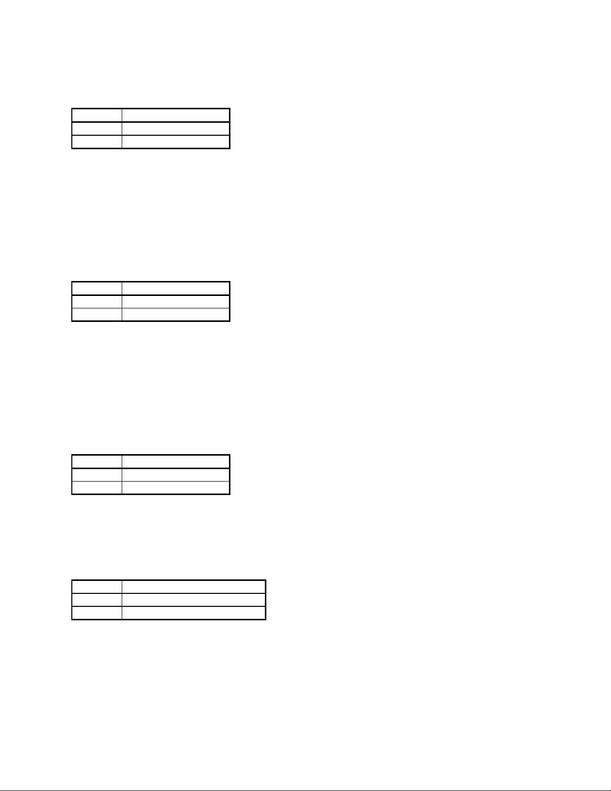
s1, bit 5: CTCSS ACTIVE. This bit indicates whether or not a valid CTCSS tone is currently
being received. The CTCSS tone status is encoded as follows:
s1, bit 5 CTCSS
0 INACTIVE
1 ACTIVE
If the CTCSS ACTIVE bit is set, a READ CTCSS TONE command should be issued to read the
CTCSS tone. The READ CTCSS TONE command will always return the most recent CTCSS tone,
even if the tone is no longer being received, so the command should only be issued while the CTCSS
ACTIVE bit is set. Note that the CTCSS ACTIVE bit does not function the way the DTMF
PENDING bit does. The CTCSS ACTIVE bit is only set while a valid CTCSS tone is being received.
It does not indicate the previous occurrence of a CTCSS tone.
s1, bit 6: NRZ ACTIVE. This bit indicates whether or not valid NRZ data, such as DCS or LTR, is
currently being received. The NRZ data status is encoded as follows:
s1, bit 6 NRZ
0 INACTIVE
1 ACTIVE
If the NRZ ACTIVE bit is set, the appropriate command should be issued to read the NRZ data,
based on the state of the NRZ MODE bits. Note that the NRZ ACTIVE bit does not function the
way the DTMF PENDING bit does. It is only set while valid NRZ data is being received. It does
not indicate the previous occurrence of NRZ data.
s1, bit 7: UNUSED. This bit will always be zero.
s2, bit 0: TAPE CONTROL. This bit indicates the current tape recorder control status. The tape
recorder control status is encoded as follows:
s2, bit 0 TAPE CONTROL
0 DISABLED
1 ENABLED
The tape recorder is enabled using the ENABLE TAPE RECORDER command. The tape recorder
is disabled using the DISABLE TAPE RECORDER command.
s2, bit 1: SPEAKER CONTROL. This bit indicates the current speaker audio control status. The
speaker audio control status is encoded as follows:
s2, bit 1 SPEAKER CONTROL
0 DISABLED
1 ENABLED
The speaker audio is enabled using the ENABLE SPEAKER AUDIO command. The speaker audio
is disabled using the DISABLE SPEAKER AUDIO command.
Page 26 of 62
Page 27
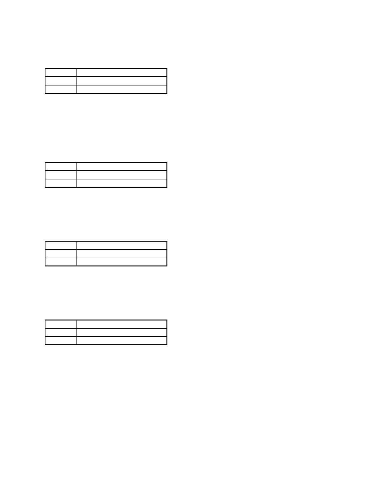
s2, bit 2: 5 KHZ SEARCH WINDOW. This bit indicates the current 5 kHz search window control
status. The 5 kHz search window control status is encoded as follows:
s2, bit 2 5 KHZ SEARCH WINDOW
0 DISABLED
1 ENABLED
The 5 kHz search window is enabled using the ENABLE 5 KHZ SEARCH WINDOW command.
The 5 kHz search window is disabled using the DISABLE 5 KHZ SEARCH WINDOW command.
s2, bit 3: UNUSED. This bit will always be zero.
s2, bit 4: AUDIO STATUS. This bit indicates the current audio status. The audio status is
encoded as follows:
s2, bit 4 AUDIO STATUS
0 NO AUDIO PRESENT
1 AUDIO PRESENT
This bit is set when audio is present on the current frequency, and cleared when no audio is
present. It provides a means to skip over dead carrier signals.
s2, bit 5: SEARCH MODE. This bit indicates the current search mode status. The search mode
status is encoded as follows:
s2, bit 5 SEARCH MODE
0 DISABLED
1 ENABLED
The search mode is enabled using the ENABLE SEARCH MODE command. The search mode is
disabled using the DISABLE SEARCH MODE command.
s2, bit 6: SCAN MODE. This bit indicates the current scan mode status. The scan mode status is
encoded as follows:
s2, bit 6 SCAN MODE
0 DISABLED
1 ENABLED
The scan mode is enabled or disabled using the WRITE SCAN MODE command.
s2, bit 7: UNUSED. This bit will always be zero.
Page 27 of 62
Page 28
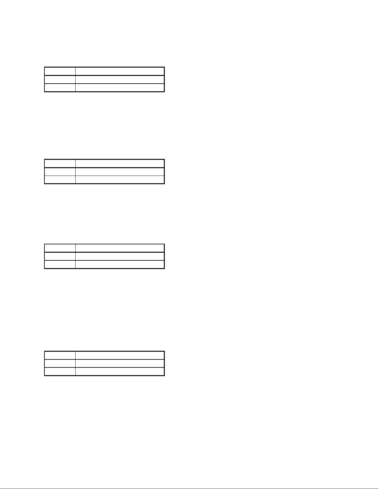
s3, bit 0: FREQUENCY RECEIVED. This bit indicates the current frequency command status.
The frequency command status is encoded as follows:
s3, bit 0 FREQUENCY COMMAND
0 NOT RECEIVED
1 RECEIVED
This bit is set upon successful reception of a valid TRANSFER FREQUENCY or WRITE
FREQUENCY command. It provides a means to determine if a frequency command transmitted by
the controller was executed by the receiver. This bit is automatically cleared after a READ
STATUS command.
s3, bit 1: MODE RECEIVED. This bit indicates the current mode command status. The mode
command status is encoded as follows:
s3, bit 1 MODE COMMAND
0 NOT RECEIVED
1 RECEIVED
This bit is set upon successful reception of a valid TRANSFER MODE or WRITE MODE command.
It provides a means to determine if a mode command transmitted by the controller was executed by
the receiver. This bit is automatically cleared after a READ STATUS command.
s3, bit 2: PIPELINE RECEIVED. This bit indicates the current pipeline command status. The
pipeline command status is encoded as follows:
s3, bit 2 PIPELINE COMMAND
0 NOT RECEIVED
1 RECEIVED
This bit is set upon successful reception of a valid TRANSFER NEXT FREQUENCY/MODE
command. It provides a means to determine if a pipelined frequency/mode command transmitted by
the controller was executed by the receiver. This bit is automatically cleared after a READ
STATUS command.
s3, bit 3: UNUSED. This bit will always be zero.
s3, bit 4: DATA AVAILABLE. This bit indicates the current overall decoder data status. The
decoder data status is encoded as follows:
s3, bit 4 DECODER DATA
0 NOT AVAILABLE
1 AVAILABLE
This bit is set upon reception of any new decoder data that is different from the previous data, or if
the decoder status changes, such as a CTCSS tone no longer being received. It provides the same
information as the DATA AVAILABLE (CTS) signal on the RS-232 interface. This bit is
automatically cleared after a READ STATUS command.
s3, bit 5: RESERVED. This bit is reserved for future use.
Page 28 of 62
Page 29
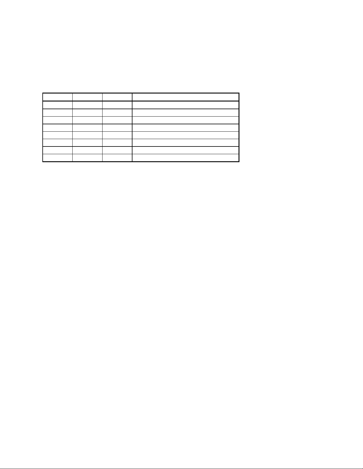
s3, bit 6: RESERVED. This bit is reserved for future use.
s3, bit 7: UNUSED. This bit will always be zero.
s4, bits 0 - 2: DECODE MODE. These three bits collectively indicate the currently selected
decode mode. The various decode modes are encoded as follows:
s4, bit 2 s4, bit 1 s4, bit 0 DECODE MODE
0 0 0 CTCSS/DCS DECODE
0 0 1 LTR DECODE
0 1 0 Reserved
0 1 1 Reserved
1 0 0 Reserved
1 0 1 Reserved
1 1 0 Reserved
1 1 1 Reserved
The decode mode is an indication of the type of NRZ data available when the NRZ ACTIVE bit is
set.
s4, bit 3: UNUSED. This bit will always be zero.
s4, bit 4: RESERVED. This bit is reserved for future use.
s4, bit 5: RESERVED. This bit is reserved for future use.
s4, bit 6: RESERVED. This bit is reserved for future use.
s4, bit 7: UNUSED. This bit will always be zero.
Page 29 of 62
Page 30
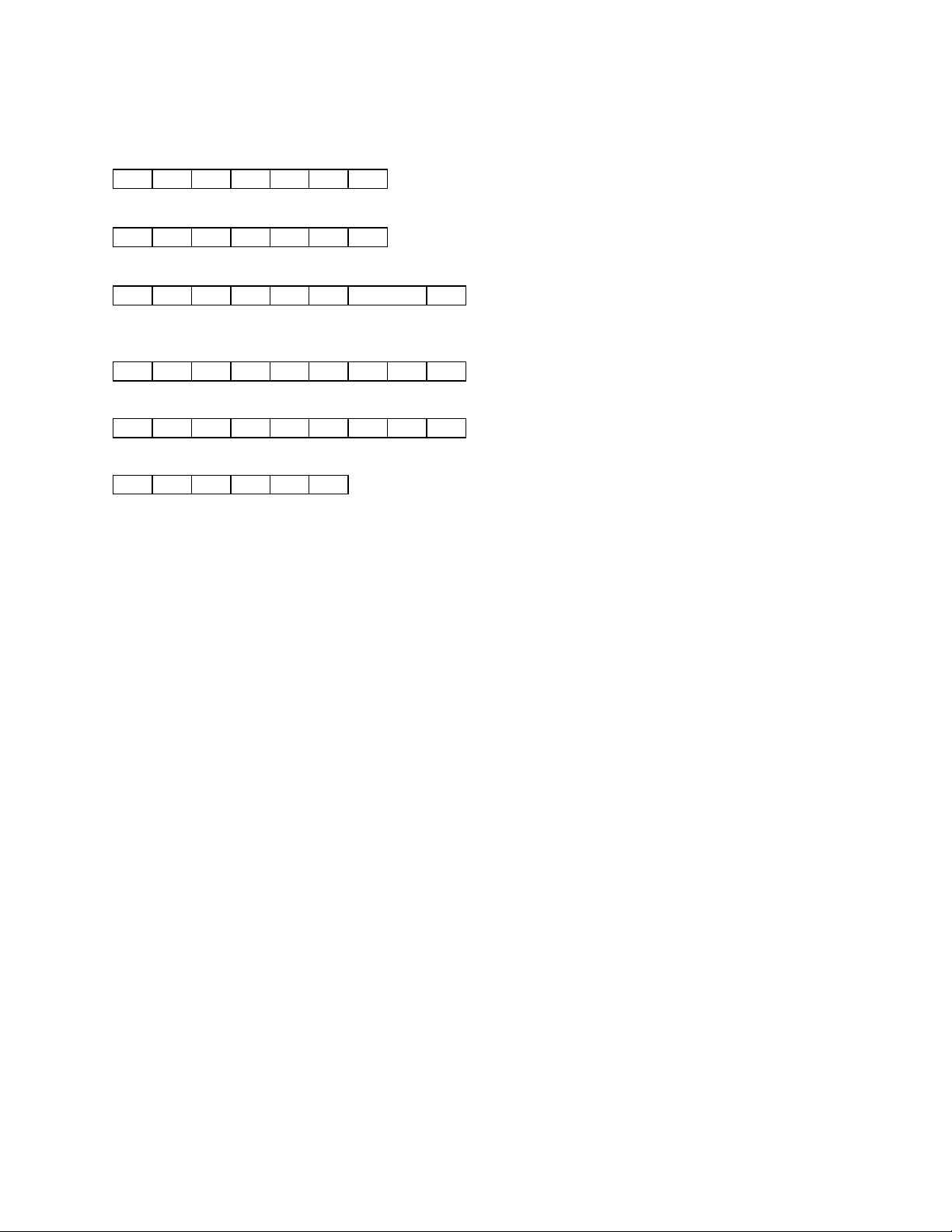
READ CTCSS TONE
Command:
FE FE ra ta 7F 06 FD
Example:
FE FE 80 E0 7F 06 FD
Response:
FE FE ta ra 7F 06 sd FD
Examples:
82.5 Hz
FE FE E0 80 7F 06 08 25 FD
103.5 Hz
FE FE E0 80 7F 06 10 35 FD
Error
FE FE E0 80 FA FD
Description:
This command instructs the unit to send the most recent CTCSS tone, provided that CTCSS/DCS
decode mode is selected.
The CTCSS data is in the form of 2 bytes, each consisting of 2 BCD digits. The order of the 4 BCD
digits is as follows: 100 Hz digit, 10 Hz digit, 1 Hz digit, 0.1 Hz digit. See the examples shown
above. A complete list of the CTCSS tones decoded by the OPTOCOM is given in Table 3.
It should be noted that this command will always return the most recent CTCSS tone, even if the
tone is no longer being received. Therefore, the CTCSS ACTIVE bit should be checked to determine
whether or not a CTCSS tone is currently being received. The CTCSS ACTIVE bit is accessed
through the READ STATUS command. If the frequency, mode, or decode mode is changed, the
CTCSS tone is cleared.
If the command length is incorrect, or if CTCSS/DCS decode mode is not selected, then the
command is ignored, and the error response is returned.
Page 30 of 62
Page 31
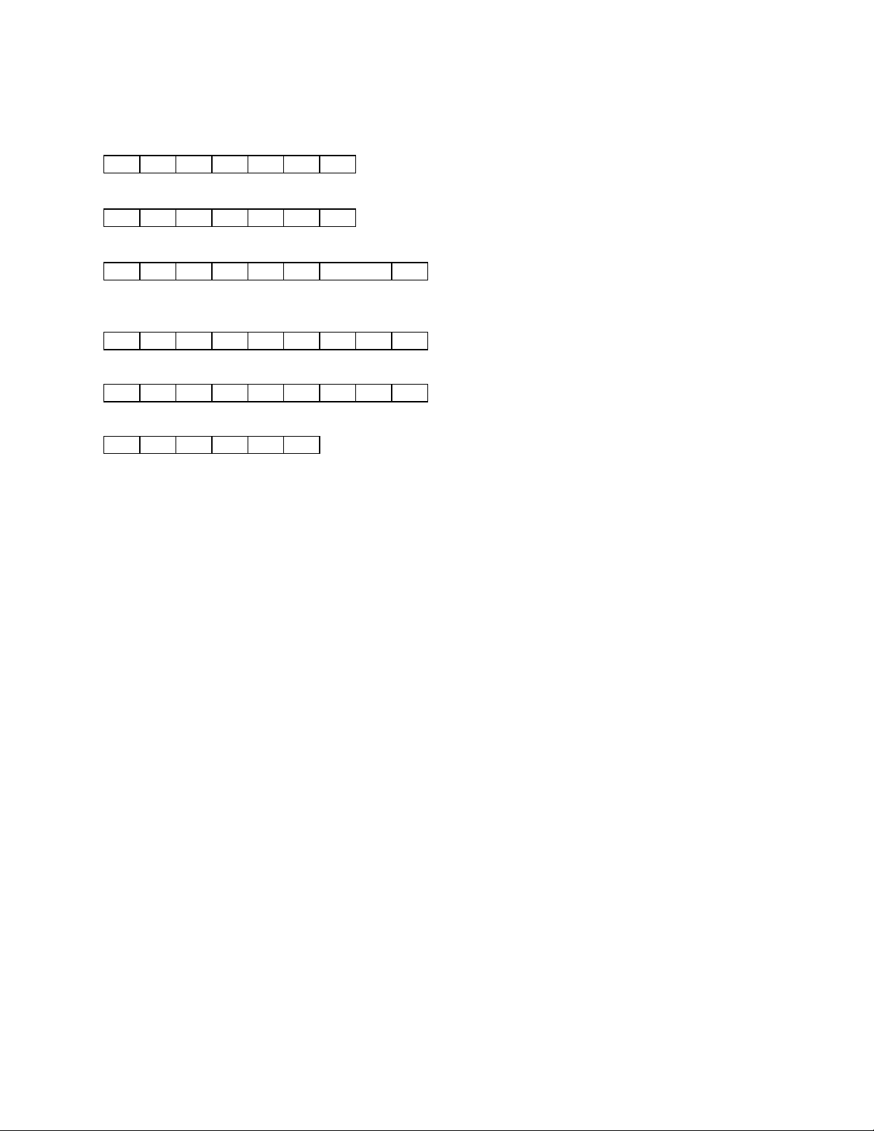
READ DCS CODE
Command:
FE FE ra ta 7F 07 FD
Example:
FE FE 80 E0 7F 07 FD
Response:
FE FE ta ra 7F 07 sd FD
Examples:
023
FE FE E0 80 7F 07 00 23 FD
732
FE FE E0 80 7F 07 07 32 FD
Error
FE FE E0 80 FA FD
Description:
This command instructs the unit to send the most recent DCS code, provided that CTCSS/DCS
decode mode is selected.
The DCS data is in the form of 2 bytes, each consisting of 2 BCD digits. The order of the 4 BCD
digits is as follows: unused digit (always 0), 100's digit, 10's digit, 1's digit. See the examples shown
above. A complete list of the DCS codes decoded by the OPTOCOM is given in Table 4.
It should be noted that this command will always return the most recent DCS code, even if the code
is no longer being received. Therefore, the NRZ ACTIVE bit should be checked to determine
whether or not a DCS code is currently being received. The NRZ ACTIVE bit is accessed through
the READ STATUS command. If the frequency, mode, or decode mode is changed, the DCS code is
cleared.
If the command length is incorrect, or if CTCSS/DCS decode mode is not selected, then the
command is ignored, and the error response is returned.
Page 31 of 62
Page 32
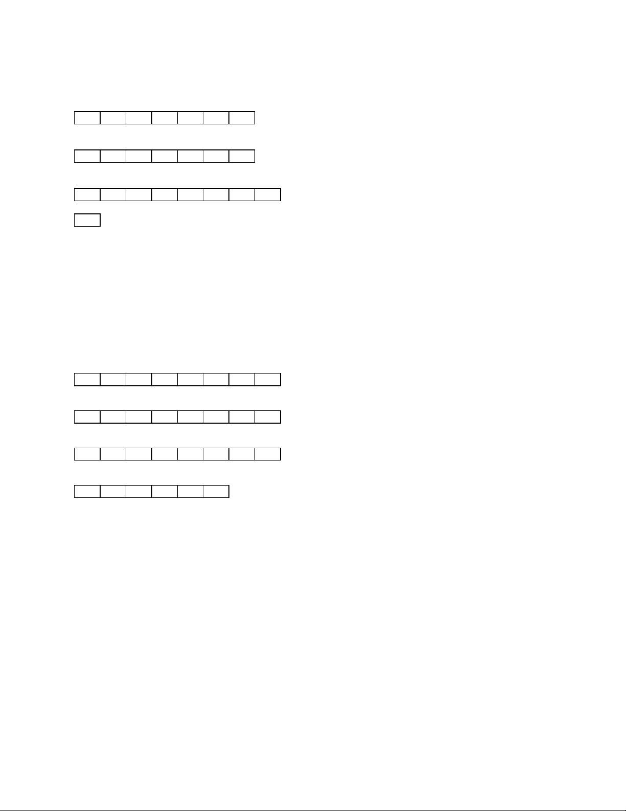
READ DTMF DIGIT
Command:
FE FE ra ta 7F 08 FD
Example:
FE FE 80 E0 7F 08 FD
Response:
FE FE ta ra 7F 08 sd FD
is a BCD value representing the next DTMF digit. BCD values are encoded as follows:
sd
00: "0" 08: "8" 99: DTMF Buffer Empty
01: "1" 09: "9"
02: "2" 10: "A"
03: "3" 11: "B"
04: "4" 12: "C"
05: "5" 13: "D"
06: "6" 14: "*"
07: "7" 15: "#"
Examples:
"3"
FE FE E0 80 7F 08 03 FD
"A"
FE FE E0 80 7F 08 10 FD
DTMF Buffer Empty
FE FE E0 80 7F 08 99 FD
Error
FE FE E0 80 FA FD
Description:
This command instructs the unit to send the next DTMF digit waiting in the 31-digit DTMF buffer.
The DTMF data is in the form of 1 byte, consisting of 2 BCD digits. The BCD digits are encoded as
shown above. Each issuance of the READ DTMF DIGIT command causes the next digit in the
DTMF buffer to be sent in the order it was received, in a First-In-First-Out (FIFO) fashion. Once
the DTMF buffer is empty, the READ DTMF DIGIT command returns the DTMF Buffer Empty
code. See the examples shown above. If the frequency, mode, or decode mode is changed, the
DTMF buffer is cleared.
If the command length is incorrect, then the command is ignored, and the error response is
returned.
Page 32 of 62
Page 33
READ IDENTIFICATION
Command:
FE FE ra ta 7F 09 FD
Example:
FE FE 80 E0 7F 09 FD
Response:
FE FE ta ra 7F 09 id sv iv FD
Examples:
OPTOCOM, software version 1.4, interface version 1.1
FE FE E0 80 7F 09 50 54 43 14 11 FD
Error
FE FE E0 80 FA FD
Description:
This command instructs the unit to send the identification data.
It should be noted that when OptoScan535 emulation mode is enabled, the OptoScan535
identification data is sent, instead of the OPTOCOM identification data described in this
document. This provides backward compatibility with legacy software written for the
OptoScan535. OptoScan535 emulation mode is enabled and disabled by use of the WRITE CI-5
INTERFACE MODE command.
The identification data is in the form of 5 bytes, each consisting of 2 BCD digits. The first 6 BCD
digits uniquely identify the device. The next 2 BCD digits indicate the current software version.
The last 2 BCD digits indicate the current interface version. See the example shown above.
If the command length is incorrect, then the command is ignored, and the error response is
returned.
Page 33 of 62
Page 34
ENABLE SPEAKER AUDIO
Command:
FE FE ra ta 7F 0A FD
Example:
FE FE 80 E0 7F 0A FD
Response:
FE FE ta ra FB or FA FD
Examples:
OK
FE FE E0 80 FB FD
Error
FE FE E0 80 FA FD
Description:
This command enables the speaker audio.
The speaker audio can be enabled and disabled under software control to facilitate selective
scanning. This feature allows the software to mute the speaker audio unless a certain CTCSS tone,
or DCS code, or DTMF digit sequence is detected on a particular frequency.
If SCAN mode is enabled, then the speaker audio change is not processed immediately, but is saved
to take effect later when SCAN mode is disabled.
If the command length is incorrect, then the command is ignored, and the error response is
returned.
Page 34 of 62
Page 35
DISABLE SPEAKER AUDIO
Command:
FE FE ra ta 7F 0B FD
Example:
FE FE 80 E0 7F 0B FD
Response:
FE FE ta ra FB or FA FD
Examples:
OK
FE FE E0 80 FB FD
Error
FE FE E0 80 FA FD
Description:
This command disables the speaker audio.
The speaker audio can be enabled and disabled under software control to facilitate selective
scanning. This feature allows the software to mute the speaker audio unless a certain CTCSS tone,
or DCS code, or DTMF digit sequence is detected on a particular frequency.
If SCAN mode is enabled, then the speaker audio change is not processed immediately, but is saved
to take effect later when SCAN mode is disabled.
If the command length is incorrect, then the command is ignored, and the error response is
returned.
Page 35 of 62
Page 36
ENABLE 5 KHZ SEARCH WINDOW
Command:
FE FE ra ta 7F 0C FD
Example:
FE FE 80 E0 7F 0C FD
Response:
FE FE ta ra FB or FA FD
Examples:
OK
FE FE E0 80 FB FD
Error
FE FE E0 80 FA FD
Description:
This command enables the 5 kHz search window.
The search mode can be enabled by the software when a limit search is conducted. When search
mode is enabled, a squelch open indication is only given if the currently recieved signal is centered
on the receiver's tuned frequency. This provides more selective squelch operation, which helps
prevent the receiver from stopping 5 or 10 kHz away from the actual transmitter frequency. In
addition, the 5 kHz search window can be enabled to make the squelch indication even more
selective. When 5 kHz channel spacing is used, the 5 kHz search window should be enabled. When
12.5 kHz or wider channel spacing is used, the 5 kHz search window should be disabled. When the
search mode is disabled, the setting of the 5 kHz search window has no effect.
If SCAN mode is enabled, then the 5 kHz search window change is not processed immediately, but
is saved to take effect later when SCAN mode is disabled.
If the command length is incorrect, then the command is ignored, and the error response is
returned.
Page 36 of 62
Page 37
DISABLE 5 KHZ SEARCH WINDOW
Command:
FE FE ra ta 7F 0D FD
Example:
FE FE 80 E0 7F 0D FD
Response:
FE FE ta ra FB or FA FD
Example:
OK
FE FE E0 80 FB FD
Error
FE FE E0 80 FA FD
Description:
This command disables the 5 kHz search window.
The search mode can be enabled by the software when a limit search is conducted. When search
mode is enabled, a squelch open indication is only given if the currently recieved signal is centered
on the receiver's tuned frequency. This provides more selective squelch operation, which helps
prevent the receiver from stopping 5 or 10 kHz away from the actual transmitter frequency. In
addition, the 5 kHz search window can be enabled to make the squelch indication even more
selective. When 5 kHz channel spacing is used, the 5 kHz search window should be enabled. When
12.5 kHz or wider channel spacing is used, the 5 kHz search window should be disabled. When the
search mode is disabled, the setting of the 5 kHz search window has no effect.
If SCAN mode is enabled, then the 5 kHz search window change is not processed immediately, but
is saved to take effect later when SCAN mode is disabled.
If the command length is incorrect, then the command is ignored, and the error response is
returned.
Page 37 of 62
Page 38
TRANSFER NEXT FREQUENCY/MODE
Command:
FE FE ra ta 7F 0E frequency md dm of FD
is a BCD value representing the desired operating mode. BCD values are encoded as
md
follows:
02: AM
05: FM-narrowband
06: FM-wideband
is a BCD value representing the desired decode mode. BCD values are encoded as follows:
dm
00: CTCSS/DCS DECODE mode
01: LTR DECODE mode
02: Reserved
03: Reserved
04: Reserved
05: Reserved
06: Reserved
07: Reserved
is a binary value representing various operating flags. Individual bits are encoded as
of
follows:
bit 0: 0 = audio enabled, 1 = audio disabled
bit 1: 0 = search mode disabled, 1 = search mode enabled
bit 2: 0 = 5 kHz search window disabled, 1 = 5 kHz search window enabled
bit 3: Unused. Always 0.
bit 4: Reserved
bit 5: Reserved
bit 6: Reserved
bit 7: Unused. Always 0.
Examples:
435.162500 MHz, FM-narrowband, LTR DECODE mode, audio disabled, search mode enabled, 5
kHz search window enabled
FE FE 80 E0 7F 0E 00 25 16 35 04 05 01 07 FD
99.500000 MHz, FM-wideband, CTCSS/DCS DECODE mode, audio enabled, search mode disabled,
5 kHz search window disabled
FE FE 80 E0 7F 0E 00 00 50 99 00 06 00 00 FD
Response:
NONE
Page 38 of 62
Page 39

Description:
This command selects the next operating frequency and operating mode of the receiver. However,
no response is returned under any condition.
It should be noted that when OptoScan535 emulation mode is enabled, the frequency/mode data
conforms to the OptoScan535 format, instead of the format described in this document. This
provides backward compatibility with legacy software written for the OptoScan535.
OptoScan535 emulation mode is enabled and disabled by use of the WRITE CI-5 INTERFACE
MODE command.
The frequency data is in the form of 5 bytes, each consisting of 2 BCD digits. The order of the 10
BCD digits is as follows: 10 Hz digit, 1 Hz digit, 1 kHz digit, 100 Hz digit, 100 kHz digit, 10 kHz
digit, 10 MHz digit, 1 MHz digit, 1 GHz digit, 100 MHz digit. The mode data is in the form of 1
byte, consisting of 2 BCD digits. The decode mode data is in the form of 1 byte, consisting of 2 BCD
digits. The operating flag data is in the form of 1 byte, consisting of 6 operating flag bits and 2
unused bits which are always cleared. The unused bits ensure that the operating flag data always
appears as valid BCD digits. See the examples shown above.
This command allows the software to make use of the OPTOCOM pipelined tuning feature. The
next frequency, mode, decode mode, and operating flag data specified by this command are stored
by the OPTOCOM. However, the new parameters do not take effect until a transition is detected
on the RTS interface signal. This feature allows the next frequency and mode to be sent to the
receiver while waiting for the receiver to settle on the current frequency and mode.
If the command length is incorrect, or if the received frequency is not in the range 25 - 520 MHz,
760 - 823.995 MHz, 849 - 868.995 MHz, or 894 - 1300 MHz, or is not an even multiple of 5 kHz or
12.5 kHz, or if the received mode, decode mode, or operating flag data is not valid, then the
command is ignored.
Page 39 of 62
Page 40
ENABLE SEARCH MODE
Command:
FE FE ra ta 7F 0F FD
Example:
FE FE 80 E0 7F 0F FD
Response:
FE FE ta ra FB or FA FD
Examples:
OK
FE FE E0 80 FB FD
Error
FE FE E0 80 FA FD
Description:
This command enables the search mode.
The search mode can be enabled by the software when a limit search is conducted. When search
mode is enabled, a squelch open indication is only given if the currently recieved signal is centered
on the receiver's tuned frequency. This provides more selective squelch operation, which helps
prevent the receiver from stopping 5 or 10 kHz away from the actual transmitter frequency. In
addition, the 5 kHz search window can be enabled to make the squelch indication even more
selective. When 5 kHz channel spacing is used, the 5 kHz search window should be enabled. When
12.5 kHz or wider channel spacing is used, the 5 kHz search window should be disabled. When the
search mode is disabled, the setting of the 5 kHz search window has no effect.
If SCAN mode is enabled, then the search mode change is not processed immediately, but is saved
to take effect later when SCAN mode is disabled.
If the command length is incorrect, then the command is ignored, and the error response is
returned.
Page 40 of 62
Page 41
DISABLE SEARCH MODE
Command:
FE FE ra ta 7F 10 FD
Example:
FE FE 80 E0 7F 10 FD
Response:
FE FE ta ra FB or FA FD
Examples:
OK
FE FE E0 80 FB FD
Error
FE FE E0 80 FA FD
Description:
This command disables the search mode.
The search mode can be enabled by the software when a limit search is conducted. When search
mode is enabled, a squelch open indication is only given if the currently recieved signal is centered
on the receiver's tuned frequency. This provides more selective squelch operation, which helps
prevent the receiver from stopping 5 or 10 kHz away from the actual transmitter frequency. In
addition, the 5 kHz search window can be enabled to make the squelch indication even more
selective. When 5 kHz channel spacing is used, the 5 kHz search window should be enabled. When
12.5 kHz or wider channel spacing is used, the 5 kHz search window should be disabled. When the
search mode is disabled, the setting of the 5 kHz search window has no effect.
If SCAN mode is enabled, then the search mode change is not processed immediately, but is saved
to take effect later when SCAN mode is disabled.
If the command length is incorrect, then the command is ignored, and the error response is
returned.
Page 41 of 62
Page 42
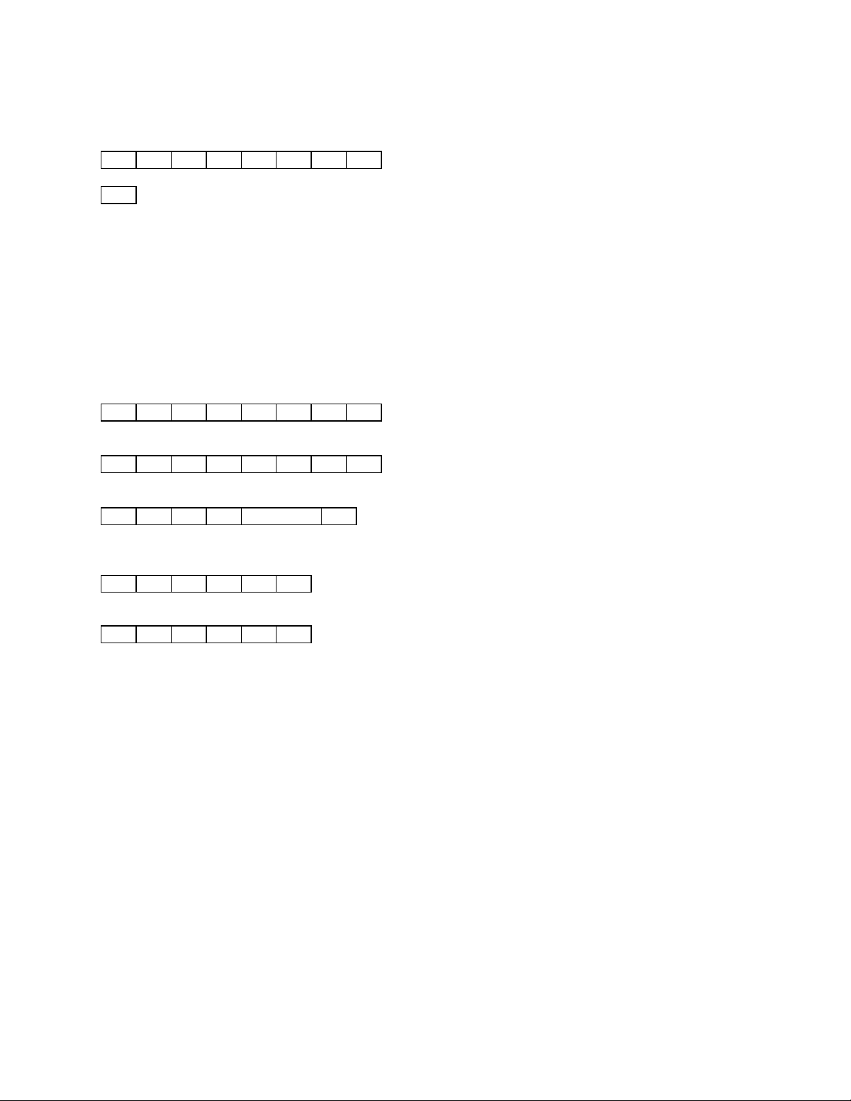
WRITE DECODE MODE
Command:
FE FE ra ta 7F 11 dm FD
is a BCD value representing the desired decode mode. BCD values are encoded as follows:
dm
00: CTCSS/DCS DECODE mode
01: LTR DECODE mode
02: Reserved
03: Reserved
04: Reserved
05: Reserved
06: Reserved
07: Reserved
Examples:
CTCSS/DCS DECODE mode
FE FE 80 E0 7F 11 00 FD
LTR DECODE mode
FE FE 80 E0 7F 11 01 FD
Response:
FE FE ta ra FB or FA FD
Examples:
OK
FE FE E0 80 FB FD
Error
FE FE E0 80 FA FD
Description:
This command selects the decode mode. However, this command is not valid when OptoScan535
emulation mode is enabled.
The decode mode data is in the form of 1 byte, consisting of 2 BCD digits. See the examples shown
above.
If SCAN mode is enabled, then the decode mode change is not processed immediately, but is saved
to take effect later when SCAN mode is disabled.
If the command length is incorrect, or if the received decode mode data is not valid, or if
OptoScan535 emulation mode is enabled, then the command is ignored, and the error response is
returned.
Page 42 of 62
Page 43
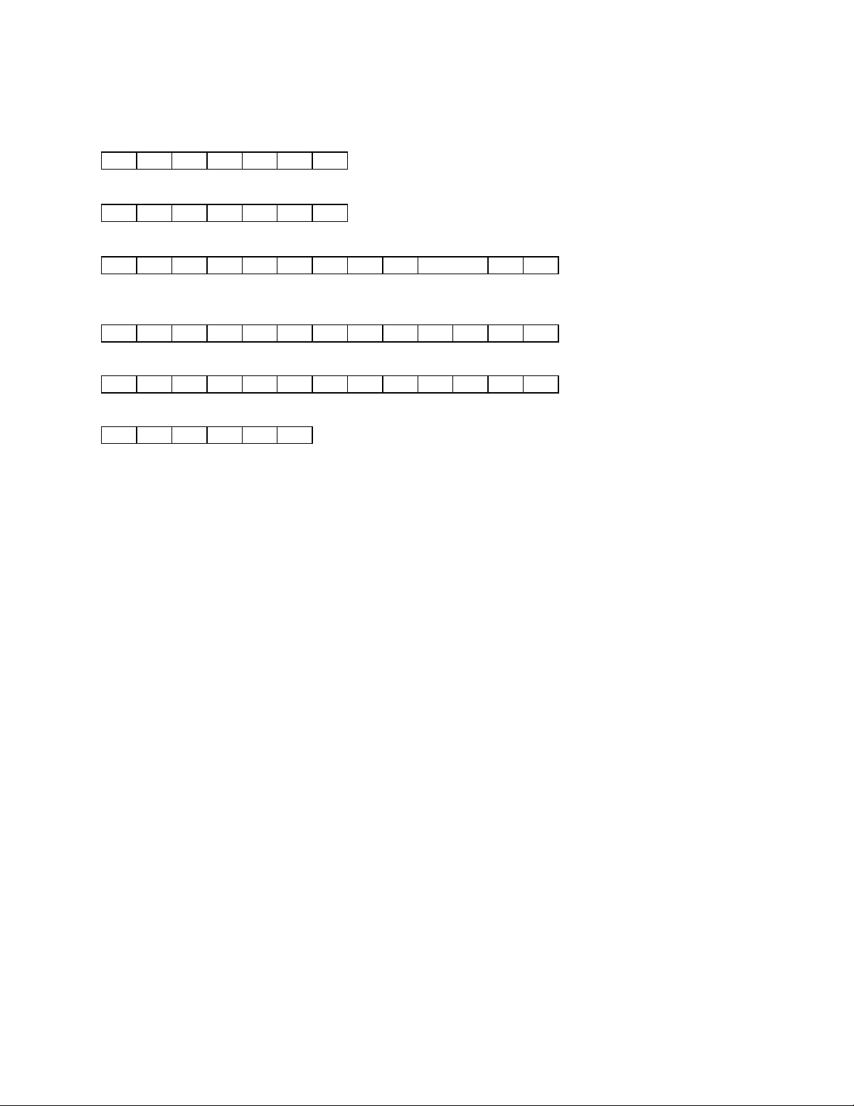
READ LTR DATA
Command:
FE FE ra ta 7F 12 FD
Example:
FE FE 80 E0 7F 12 FD
Response:
FE FE ta ra 7F 12 ad gd hd id fd FD
Examples:
AREA = 0, GOTO = 05, HOME = 17, ID = 23, FREE = 07
FE FE E0 80 7F 12 00 05 17 00 23 07 FD
AREA = 1, GOTO = 11, HOME = 03, ID = 176, FREE = 08
FE FE E0 80 7F 12 01 11 03 01 76 08 FD
Error
FE FE E0 80 FA FD
Description:
This command instructs the unit to send the most recent LTR data, provided that LTR decode mode
is selected. However, this command is not valid when OptoScan535 emulation mode is enabled.
The LTR data is in the form of 6 bytes, each consisting of 2 BCD digits. The order of the 12 BCD
digits is as follows: unused digit (always 0), AREA code digit, GOTO repeater 10's digit, GOTO
repeater 1's digit, HOME repeater 10's digit, HOME repeater 1's digit, unused digit (always 0), ID
code 100's digit, ID code 10's digit, ID code 1's digit, FREE repeater 10's digit, FREE repeater 1’s
digit. See the examples shown above.
It should be noted that this command will always return the most recent LTR data, even if the data
is no longer being received. Therefore, the NRZ ACTIVE bit should be checked to determine
whether or not LTR data is currently being received. The NRZ ACTIVE bit is accessed through the
READ STATUS command. If the frequency, mode, or decode mode is changed, the LTR data is
cleared.
If the command length is incorrect, or if LTR decode mode is not selected, or if OptoScan535
emulation mode is enabled, then the command is ignored, and the error response is returned.
Page 43 of 62
Page 44
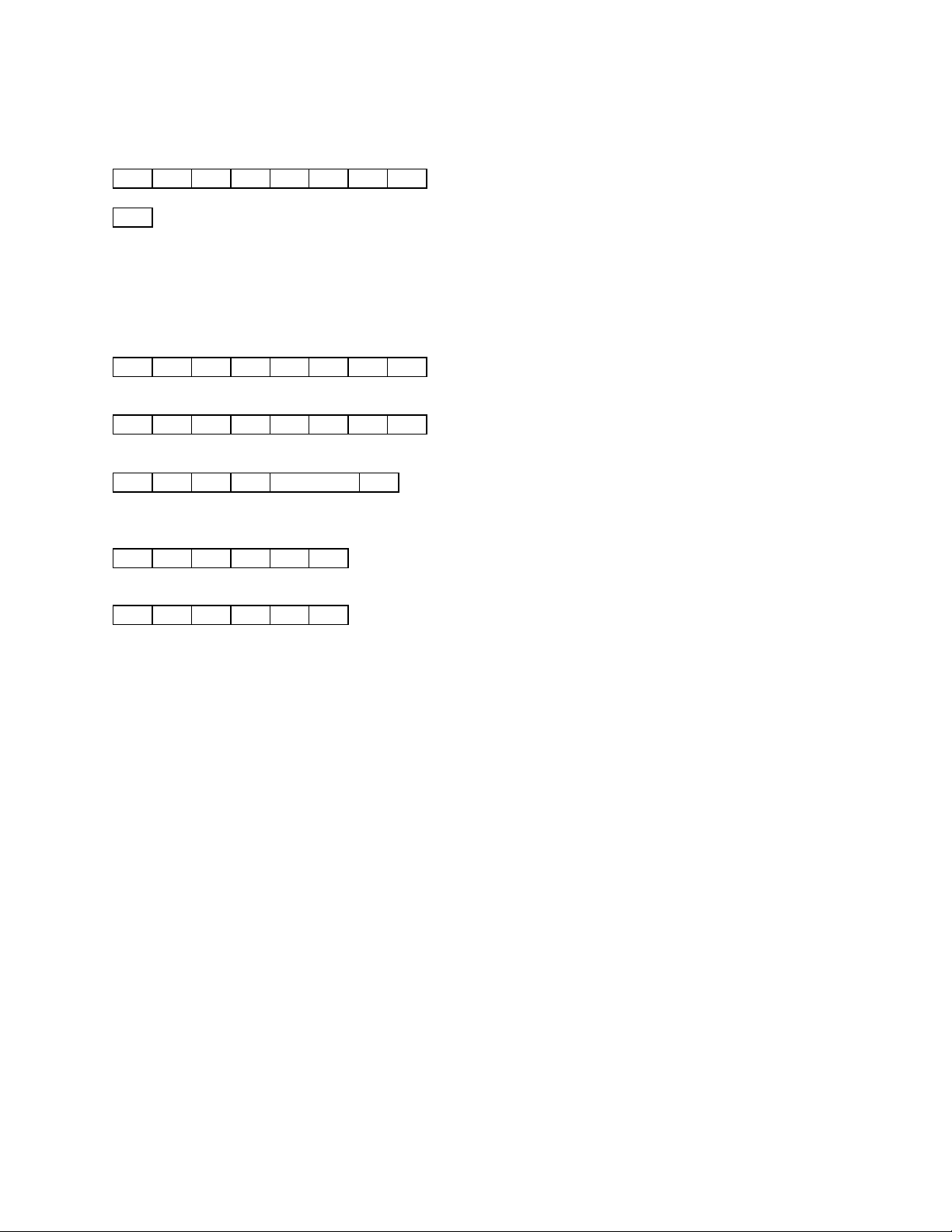
WRITE VOLUME/SQUELCH CONTROL
Command:
FE FE ra ta 7F 13 vs FD
is a BCD value representing the desired volume/squelch control mode. BCD values are
vs
encoded as follows:
00: LOCAL VOLUME/SQUELCH CONTROL mode
01: REMOTE VOLUME/SQUELCH CONTROL mode
Examples:
LOCAL VOLUME/SQUELCH CONTROL mode
FE FE 80 E0 7F 13 00 FD
REMOTE VOLUME/SQUELCH CONTROL mode
FE FE 80 E0 7F 13 01 FD
Response:
FE FE ta ra FB or FA FD
Examples:
OK
FE FE E0 80 FB FD
Error
FE FE E0 80 FA FD
Description:
This command selects the volume/squelch control mode.
The volume/squelch control mode data is in the form of 1 byte, consisting of 2 BCD digits. See the
examples shown above. If LOCAL VOLUME/SQUELCH CONTROL mode is selected, then the
front panel volume and squelch controls are active. If REMOTE VOLUME/SQUELCH CONTROL
mode is selected, then the front panel volume and squelch controls are ignored, and the volume and
squelch settings are controlled using the WRITE VOLUME SETTING and WRITE SQUELCH
SETTING commands, respectively.
If the command length is incorrect, or if the received volume/squelch control mode data is not valid,
then the command is ignored, and the error response is returned.
Page 44 of 62
Page 45
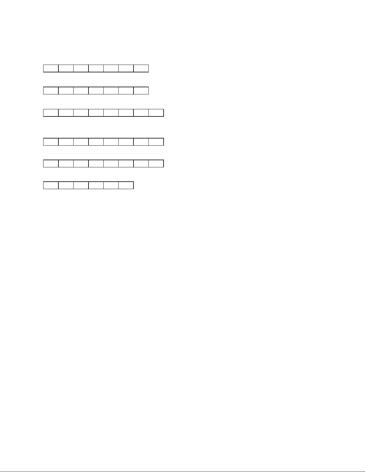
READ VOLUME SETTING
Command:
FE FE ra ta 7F 14 FD
Example:
FE FE 80 E0 7F 14 FD
Response:
FE FE ta ra 7F 14 vs FD
Examples:
29
FE FE E0 80 7F 14 29 FD
37
FE FE E0 80 7F 14 37 FD
Error
FE FE E0 80 FA FD
Description:
This command instructs the unit to send the current active volume setting.
The volume setting data is in the form of 1 byte, consisting of 2 BCD digits. The order of the 2 BCD
digits is as follows: 10's digit, 1's digit. The volume setting data is in the range 0 - 99, with 0
representing minimum volume, and 99 representing maximum volume. See the examples shown
above.
It should be noted that the volume setting data returned depends on whether LOCAL
VOLUME/SQUELCH CONTROL or REMOTE VOLUME/SQUELCH CONTROL is selected. If
LOCAL VOLUME/SQUELCH CONTROL is selected, then the current setting of the front panel
volume control is returned. If REMOTE VOLUME/SQUELCH CONTROL is selected, then the
current volume setting selected by the WRITE VOLUME SETTING command is returned.
If the command length is incorrect, then the command is ignored, and the error response is
returned.
Page 45 of 62
Page 46
WRITE VOLUME SETTING
Command:
FE FE ra ta 7F 15 vs FD
Examples:
07
FE FE 80 E0 7F 15 07 FD
55
FE FE 80 E0 7F 15 55 FD
Response:
FE FE ta ra FB or FA FD
Examples:
OK
FE FE E0 80 FB FD
Error
FE FE E0 80 FA FD
Description:
This command writes the volume setting.
The volume setting data is in the form of 1 byte, consisting of 2 BCD digits. The order of the 2 BCD
digits is as follows: 10's digit, 1's digit. The volume setting data must be in the range 0 - 99, with 0
representing minimum volume, and 99 representing maximum volume. See the examples shown
above.
It should be noted that the volume setting data applies only to REMOTE VOLUME/SQUELCH
CONTROL mode. If LOCAL VOLUME/SQUELCH CONTROL mode is selected, then the volume
setting data is stored until REMOTE VOLUME/SQUELCH CONTROL mode is selected.
If the command length is incorrect, or if the received volume setting data is not in the range 0 - 99,
then the command is ignored, and the error response is returned.
Page 46 of 62
Page 47
READ SQUELCH SETTING
Command:
FE FE ra ta 7F 16 FD
Example:
FE FE 80 E0 7F 16 FD
Response:
FE FE ta ra 7F 16 ss FD
Examples:
26
FE FE E0 80 7F 16 26 FD
83
FE FE E0 80 7F 16 83 FD
Error
FE FE E0 80 FA FD
Description:
This command instructs the unit to send the current active squelch setting.
The squelch setting data is in the form of 1 byte, consisting of 2 BCD digits. The order of the 2 BCD
digits is as follows: 10's digit, 1's digit. The squelch setting data is in the range 0 - 99, with 0
representing minimum squelch, and 99 representing maximum squelch. See the examples shown
above.
It should be noted that the squelch setting data returned depends on whether LOCAL
VOLUME/SQUELCH CONTROL or REMOTE VOLUME/SQUELCH CONTROL is selected. If
LOCAL VOLUME/SQUELCH CONTROL is selected, then the current setting of the front panel
squelch control is returned. If REMOTE VOLUME/SQUELCH CONTROL is selected, then the
current squelch setting selected by the WRITE SQUELCH SETTING command is returned.
If the command length is incorrect, then the command is ignored, and the error response is
returned.
Page 47 of 62
Page 48
WRITE SQUELCH SETTING
Command:
FE FE ra ta 7F 17 ss FD
Examples:
0
FE FE 80 E0 7F 17 00 FD
31
FE FE 80 E0 7F 17 31 FD
Response:
FE FE ta ra FB or FA FD
Examples:
OK
FE FE E0 80 FB FD
Error
FE FE E0 80 FA FD
Description:
This command writes the squelch setting.
The squelch setting data is in the form of 1 byte, consisting of 2 BCD digits. The order of the 2 BCD
digits is as follows: 10's digit, 1's digit. The squelch setting data must be in the range 0 - 99, with 0
representing minimum squelch, and 99 representing maximum squelch. See the examples shown
above.
It should be noted that the squelch setting data applies only to REMOTE VOLUME/SQUELCH
CONTROL mode. If LOCAL VOLUME/SQUELCH CONTROL mode is selected, then the squelch
setting data is stored until REMOTE VOLUME/SQUELCH CONTROL mode is selected.
If the command length is incorrect, or if the received squelch setting data is not in the range 0 - 99,
then the command is ignored, and the error response is returned.
Page 48 of 62
Page 49
WRITE SCAN MODE
Command:
FE FE ra ta 7F 18 sm FD
is a BCD value representing the desired scan mode. BCD values are encoded as follows:
sm
00: SCAN mode disabled
01: SCAN mode enabled
Examples:
SCAN mode disabled
FE FE 80 E0 7F 18 00 FD
SCAN mode enabled
FE FE 80 E0 7F 18 01 FD
Response:
FE FE ta ra FB or FA FD
Examples:
OK
FE FE E0 80 FB FD
Error
FE FE E0 80 FA FD
Description:
This command enables or disables SCAN mode. However, this command is not valid when
OptoScan535 emulation mode is enabled.
The scan mode data is in the form of 1 byte, consisting of 2 BCD digits. See the examples shown
above.
When SCAN mode is enabled, the memories are scanned repetitively, from memory location 0 to the
first empty memory location. If memory location 0 is empty, then SCAN mode cannot be enabled.
If the command length is incorrect, or if the received scan mode data is not valid, or if memory
location 0 is empty, or if OptoScan535 emulation mode is enabled, then the command is ignored,
and the error response is returned.
Page 49 of 62
Page 50
READ MEMORY
Command:
FE FE ra ta 7F 19 ml FD
Examples:
Memory location 0
FE FE 80 E0 7F 19 00 FD
Memory location 47
FE FE 80 E0 7F 19 47 FD
Memory location 99
FE FE 80 E0 7F 19 99 FD
Response:
FE FE ta ra 7F 19 frequency md dm of FD
is a BCD value representing the desired operating mode. BCD values are encoded as
md
follows:
02: AM
05: FM-narrowband
06: FM-wideband
is a BCD value representing the desired decode mode. BCD values are encoded as follows:
dm
00: CTCSS/DCS DECODE mode
01: LTR DECODE mode
02: Reserved
03: Reserved
04: Reserved
05: Reserved
06: Reserved
07: Reserved
is a binary value representing various operating flags. Individual bits are encoded as
of
follows:
bit 0: 0 = audio enabled, 1 = audio disabled
bit 1: 0 = search mode disabled, 1 = search mode enabled
bit 2: 0 = 5 kHz search window disabled, 1 = 5 kHz search window enabled
bit 3: Unused. Always 0.
bit 4: 0 = squelch delay disabled, 1 = squelch delay enabled
bit 5: Reserved
bit 6: Reserved
bit 7: Unused. Always 0.
Examples:
315.575000 MHz, AM mode, CTCSS/DCS decode mode, audio enabled, search mode disabled, 5 kHz
search window disabled, squelch delay enabled
FE FE E0 80 7F 19 00 50 57 15 03 02 00 10 FD
Page 50 of 62
Page 51

1045.712500 MHz, FM-narrowband mode, LTR decode mode, audio disabled, search mode enabled,
5 kHz search window disabled, squelch delay disabled
FE FE E0 80 7F 19 00 25 71 45 10 05 01 03 FD
memory location empty
FE FE E0 80 7F 19 00 00 00 00 00 00 00 00 FD
Error
FE FE E0 80 FA FD
Description:
This command instructs the unit to send the frequency and associated data stored in the specified
memory location.
The specified memory location data is in the form of 1 byte, consisting of 2 BCD digits. The
specified memory location must be in the range 0 to 99.
The frequency data is in the form of 5 bytes, each consisting of 2 BCD digits. The order of the 10
BCD digits is as follows: 10 Hz digit, 1 Hz digit, 1 kHz digit, 100 Hz digit, 100 kHz digit, 10 kHz
digit, 10 MHz digit, 1 MHz digit, 1 GHz digit, 100 MHz digit. The mode data is in the form of 1
byte, consisting of 2 BCD digits. The decode mode data is in the form of 1 byte, consisting of 2 BCD
digits. The operating flag data is in the form of 1 byte, consisting of 6 operating flag bits and 2
unused bits which are always cleared. The unused bits ensure that the operating flag data always
appears as valid BCD digits. See the examples shown above.
If the command length is incorrect, or if the specified memory location is not in the range 0 to 99,
then the command is ignored, and the error response is returned.
Page 51 of 62
Page 52
WRITE MEMORY
Command:
FE FE ra ta 7F 1A ml frequency md dm of FD
is a BCD value representing the desired operating mode. BCD values are encoded as
md
follows:
02: AM
05: FM-narrowband
06: FM-wideband
is a BCD value representing the desired decode mode. BCD values are encoded as follows:
dm
00: CTCSS/DCS DECODE mode
01: LTR DECODE mode
02: Reserved
03: Reserved
04: Reserved
05: Reserved
06: Reserved
07: Reserved
is a binary value representing various operating flags. Individual bits are encoded as
of
follows:
bit 0: 0 = audio enabled, 1 = audio disabled
bit 1: 0 = search mode disabled, 1 = search mode enabled
bit 2: 0 = 5 kHz search window disabled, 1 = 5 kHz search window enabled
bit 3: Unused. Always 0.
bit 4: 0 = squelch delay disabled, 1 = squelch delay enabled
bit 5: Reserved
bit 6: Reserved
bit 7: Unused. Always 0.
Examples:
Memory location 23, 315.575000 MHz, AM mode, CTCSS/DCS decode mode, audio enabled, search
mode disabled, 5 kHz search window disabled, squelch delay enabled
FE FE E0 80 7F 1A 23 00 50 57 15 03 02 00 10 FD
Memory location 67, 1045.712500 MHz, FM-narrowband mode, LTR decode mode, audio disabled,
search mode enabled, 5 kHz search window disabled, squelch delay disabled
FE FE E0 80 7F 1A 67 00 25 71 45 10 05 01 03 FD
Response:
FE FE ta ra FB or FA FD
Examples:
OK
FE FE E0 80 FB FD
Error
FE FE E0 80 FA FD
Page 52 of 62
Page 53

Description:
This command writes the frequency and associated data to the specified memory location.
The specified memory location data is in the form of 1 byte, consisting of 2 BCD digits. The
specified memory location must be in the range 0 to 99.
The frequency data is in the form of 5 bytes, each consisting of 2 BCD digits. The order of the 10
BCD digits is as follows: 10 Hz digit, 1 Hz digit, 1 kHz digit, 100 Hz digit, 100 kHz digit, 10 kHz
digit, 10 MHz digit, 1 MHz digit, 1 GHz digit, 100 MHz digit. The mode data is in the form of 1
byte, consisting of 2 BCD digits. The decode mode data is in the form of 1 byte, consisting of 2 BCD
digits. The operating flag data is in the form of 1 byte, consisting of 6 operating flag bits and 2
unused bits which are always cleared. The unused bits ensure that the operating flag data always
appears as valid BCD digits. See the examples shown above.
If the command length is incorrect, or if the specified memory location is not in the range 0 to 99, or
if any of the memory data to be stored is invalid, then the command is ignored, and the error
response is returned.
Page 53 of 62
Page 54
CLEAR MEMORY
Command:
FE FE ra ta 7F 1B ml FD
Examples:
Memory location 0
FE FE 80 E0 7F 1B 00 FD
Memory location 47
FE FE 80 E0 7F 1B 47 FD
Memory location 99
FE FE 80 E0 7F 1B 99 FD
Response:
FE FE ta ra FB or FA FD
Examples:
OK
FE FE E0 80 FB FD
Error
FE FE E0 80 FA FD
Description:
This command clears the specified memory location.
The specified memory location data is in the form of 1 byte, consisting of 2 BCD digits. The
specified memory location must be in the range 0 to 99.
If memory location 0 is cleared, and SCAN mode is enabled, then SCAN mode is disabled.
If the command length is incorrect, or if the specified memory location is not in the range 0 to 99,
then the command is ignored, and the error response is returned.
Page 54 of 62
Page 55
WRITE BIT BANGER DATA RATE
Command:
FE FE ra ta 7F 1C dr FD
is a BCD value representing the desired data rate. BCD values are encoded as follows:
dr
00: 3600 bps
01: 9600 bps
Examples:
3600 bps
FE FE 80 E0 7F 1C 00 FD
9600 bps
FE FE 80 E0 7F 1C 01 FD
Response:
FE FE ta ra FB or FA FD
Examples:
OK
FE FE E0 80 FB FD
Error
FE FE E0 80 FA FD
Description:
This command selects the BitBanger data rate. The power-up default data rate is 3600 bps. See
the BitBanger MODE section for more information.
The data rate data is in the form of 1 byte, consisting of 2 BCD digits. See the examples shown
above.
If the command length is incorrect, or if the received data rate data is not valid, then the command
is ignored, and the error response is returned.
Page 55 of 62
Page 56
WRITE BIT BANGER MODE
Command:
FE FE ra ta 7F 1D ms FD
is a BCD value representing the desired mode. BCD values are encoded as follows:
ms
00: Disabled
01: Enabled
Examples:
Disable BitBanger mode
FE FE 80 E0 7F 1D 00 FD
Enable BitBanger mode
FE FE 80 E0 7F 1D 01 FD
Response:
FE FE ta ra FB or FA FD
Examples:
OK
FE FE E0 80 FB FD
Error
FE FE E0 80 FA FD
Description:
This command enables or disables the BitBanger mode. The power-up default is BitBanger
mode disabled. See the BitBanger MODE section for more information.
The mode data is in the form of 1 byte, consisting of 2 BCD digits. See the examples shown above.
If the command length is incorrect, or if the received mode data is not valid, then the command is
ignored, and the error response is returned.
Page 56 of 62
Page 57
WRITE CI-5 ADDRESS
Command:
FE FE ra ta 7F D0 security code ad FD
Examples:
CI-5 address 83
FE FE 80 E0 7F D0 94 18 72 26 49 83 FD
CI-5 address 8C
FE FE 80 E0 7F D0 94 18 72 26 49 8C FD
Response:
FE FE ta ra FB or FA FD
Examples:
OK
FE FE E0 80 FB FD
Error
FE FE E0 80 FA FD
Description:
This command selects the CI-5 interface address.
The security code is in the form of 5 bytes, each consisting of 2 BCD digits. The security code is,
therefore, a unique 10-digit code which must be correctly specified to change the CI-5 address. The
address code is in the form of 1 byte, consisting of 2 hexadecimal digits. The address code must be
in the range 80 through 8F. See the examples shown above.
Note that if the address is successfully changed, then the new address will be reflected in the
response, and all subsequent commands must be sent to the new address. If the current address is
unknown, and there is only one device on the CI-5 bus, then this command can be sent using
address 00 (all units addressed). The CI-5 address is stored in non-volatile memory, and remains
the same until the next valid address change command.
If the command length is incorrect, or if the security code or address code is not valid, then the
command is ignored, and the error response is returned.
Page 57 of 62
Page 58
WRITE CI-5 DATA RATE
Command:
FE FE ra ta 7F D1 security code dr FD
is a BCD value representing the desired CI-5 interface data rate. BCD values are encoded
dr
as follows:
00: 300 bps
01: 600 bps
02: 1200 bps
03: 2400 bps
04: 4800 bps
05: 9600 bps
06: 19200 bps
07: 38400 bps
Examples:
9600 bps
FE FE 80 E0 7F D1 38 69 84 12 76 05 FD
1200 bps
FE FE 80 E0 7F D1 38 69 84 12 76 02 FD
Response:
FE FE ta ra FB or FA FD
Examples:
OK
FE FE E0 80 FB FD
Error
FE FE E0 80 FA FD
Description:
This command selects the CI-5 interface data rate.
The security code is in the form of 5 bytes, each consisting of 2 BCD digits. The security code is,
therefore, a unique 10-digit code which must be correctly specified to change the CI-5 data rate.
The data rate code is in the form of 1 byte, consisting of 2 BCD digits. See the examples shown
above.
Note that if a valid data rate change command is received, the change takes place immediately, and
the response is transmitted at the new data rate. If the CI-5 data rate is changed, the new data
rate remains in effect until the unit is powered down. The unit always powers up with a CI-5 data
rate of 9600 bps.
If the command length is incorrect, or if the security code or data rate code is not valid, then the
command is ignored, and the error response is returned.
Page 58 of 62
Page 59
WRITE CI-5 INTERFACE MODE
Command:
FE FE ra ta 7F D2 security code im FD
is a BCD value representing the desired interface mode. BCD values are encoded as follows:
im
00: OPTOCOM interface mode
01: OptoScan535 emulation mode
Examples:
OPTOCOM interface mode
FE FE 80 E0 7F D2 15 31 48 78 60 00 FD
OptoScan535 emulation mode
FE FE 80 E0 7F D2 15 31 48 78 60 01 FD
Response:
FE FE ta ra FB or FA FD
Examples:
OK
FE FE E0 80 FB FD
Error
FE FE E0 80 FA FD
Description:
This command selects the CI-5 interface mode.
The security code is in the form of 5 bytes, each consisting of 2 BCD digits. The security code is,
therefore, a unique 10-digit code which must be correctly specified to change the CI-5 interface
mode. The interface mode data is in the form of 1 byte, consisting of 2 BCD digits. See the
examples shown above.
OptoScan535 emulation mode provides backward compatibility with legacy software written for
the OptoScan535. The CI-5 interface mode is stored in non-volatile memory, and remains the
same until the next valid interface mode change command.
If the command length is incorrect, or if the security code or interface mode data is not valid, then
the command is ignored, and the error response is returned.
Page 59 of 62
Page 60
STORE OPERATING PARAMETERS
Command:
FE FE ra ta 7F D3 FD
Example:
FE FE 80 E0 7F D3 FD
Response:
FE FE ta ra FB or FA FD
Examples:
OK
FE FE E0 80 FB FD
Error
FE FE E0 80 FA FD
Description:
This command instructs the unit to store the current operating parameters in non-volatile memory.
The operating parameters are automatically recalled from non-volatile memory on power-up.
If the command length is incorrect, then the command is ignored, and the error response is
returned.
Page 60 of 62
Page 61
RECALL OPERATING PARAMETERS
Command:
FE FE ra ta 7F D4 FD
Example:
FE FE 80 E0 7F D4 FD
Response:
FE FE ta ra FB or FA FD
Examples:
OK
FE FE E0 80 FB FD
Error
FE FE E0 80 FA FD
Description:
This command instructs the unit to recall the current operating parameters from non-volatile
memory.
The operating parameters are automatically recalled from non-volatile memory on power-up.
If the command length is incorrect, then the command is ignored, and the error response is
returned.
Page 61 of 62
Page 62

OPTOELECTRONICS, INC.
5821 N.E. 14th Avenue
Fort Lauderdale, FL 33334
Phone: (954) 771-2050
FAX: (954) 771-2052
Page 62 of 62
 Loading...