

Page 1
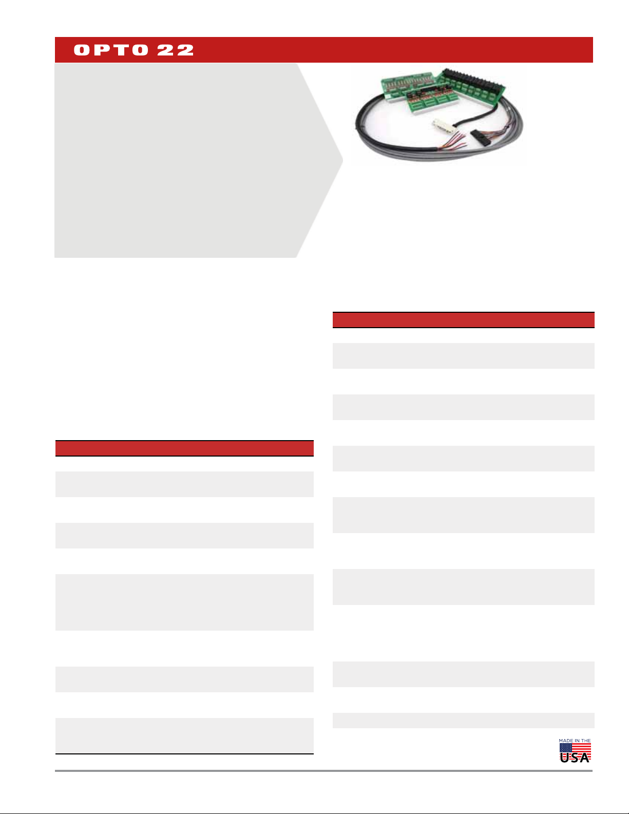
SNAP TEX CABLES AND BREAKOUT
BOARDS
Features
Extend the terminals on your SNAP I/O modules for easier,
>
cleaner wiring to field devices.
Six-foot (1.8 meter) wiring cables plug into tops of I/O
>
modules for quick replacement.
Breakout boards offer options such as fusing, power to loads,
>
and mechanical relays.
Integrate older G4 digital I/O with SNAP PAC I/O.
>
DESCRIPTION
SNAP TEX cables and breakout boards are part of the SNAP TEX family
of wiring and mounting accessories. (See form 1772 for accessories
not covered in this data sheet.) These cables and boards save time
and expense during installation, maintenance, and debugging by
reducing the time and effort required to wire field devices to SNAP I/O
modules.
Choose the cables and breakout boards for your modules based on
the table that starts on page 2. Specifications and dimensions begin
on page 5 and wiring diagrams on page 24. Assembly and installation
steps are on page 10.
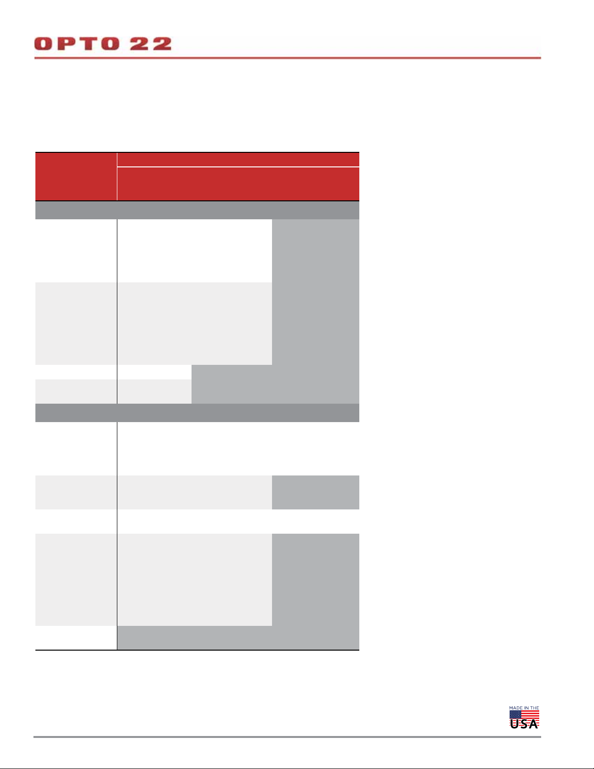
Part Numbers
Part Description
Cables
SNAP-HD-20F6
SNAP-HD-ACF6
SNAP-HD-BF6
SNAP-HD-CBF6
SNAP-HD-G4F6
SNAP-HD-G4F6N
SNAP-TEX-CBE6
SNAP-TEX-CBO6
SNAP-TEX-CBS6
OPTO 22 •
6 ft. (1.8 m) wiring cable for SNAP-AOVA-8
module, with flying leads
6 ft. (1.8 m) wiring harness assembly for SNAP
16-point digital modules; flying leads
6 ft. (1.8 m) wiring harness for 32-channel
modules and breakout boards
6 ft. (1.8 m) wiring harness for most 32-point
modules, with flying leads
6 ft. (1.8 m) header cable for SNAP-ODC-32-SNK
and SNAP-IDC-32 digital modules and G4PB16H
and G4PB16HC mounting racks. Also for
SNAP-ODC-32-SRC when connecting to a
SNAP-MR10-16C breakout board.
6 ft. (1.8 m) header cable for SNAP-IDC-32N
digital modules and G4PB16H and G4PB16HC
mounting racks
6 ft. (1.8 m), 8-wire cable for SNAP I/O modules.
Even terminals commoned, flying leads.
6 ft. (1.8 m), 8-wire cable for SNAP I/O modules.
Odd terminals commoned, flying leads.
6 ft. (1.8 m), 8-wire cable for SNAP I/O modules.
Straight-through; no common terminals. Flying
leads.
DA T A SHEET
Form 1756-200206
PAGE 1
SNAP TEX Family
SNAP TEX cables provide convenient connections from I/O modules
to field wiring. Most cables are designed to connect to breakout
boards; some cables have flying leads for direct connection to field
devices.
SNAP TEX breakout boards move terminals away from the crowded
rack area for easier installation and maintenance. Most boards can be
panel mounted or DIN-rail mounted (see page 10). See compatibility
tables starting on page 2.
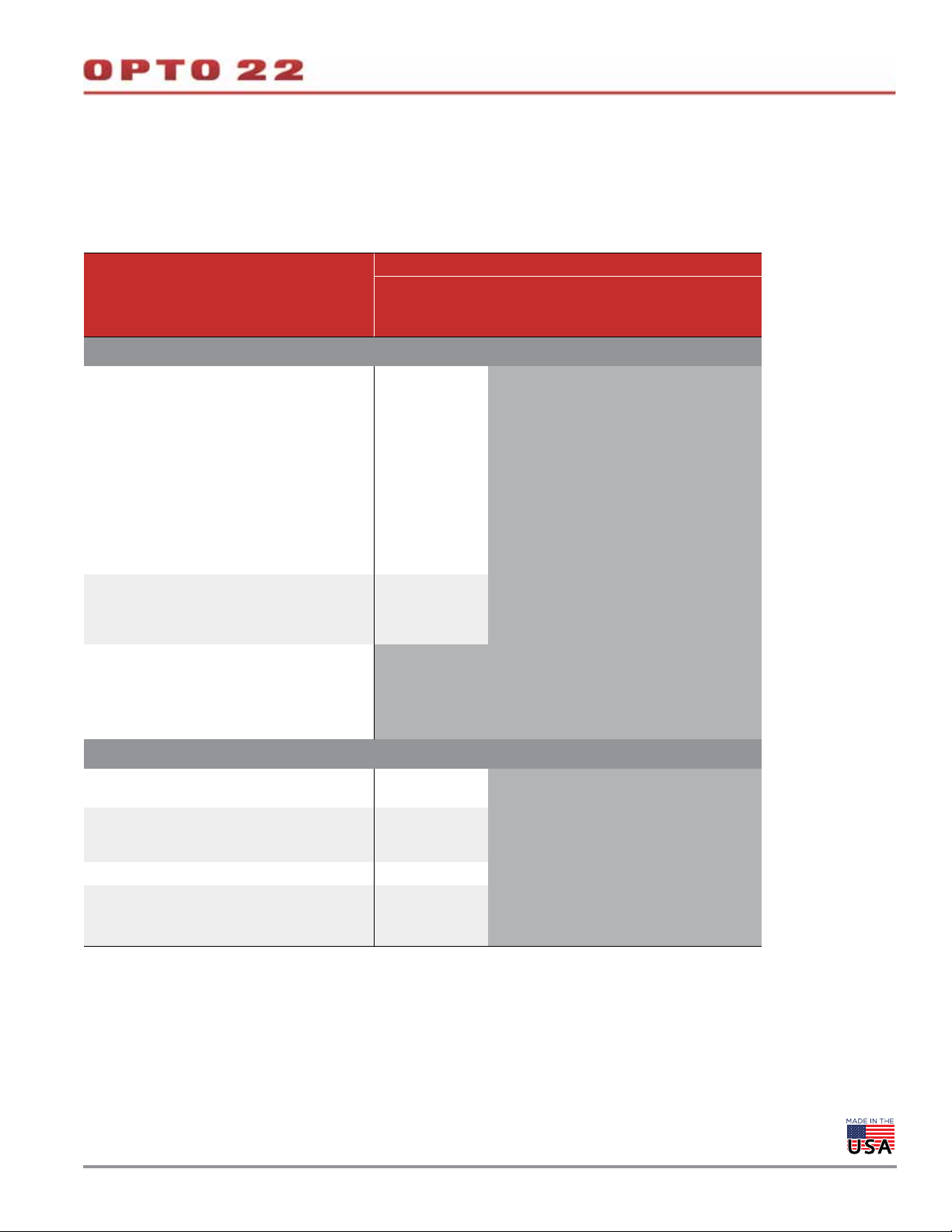
Part Numbers (continued)
Part Description
Breakout Boards
SNAP-AIMA-HDB
SNAP-AIMA-HDB-FM*
SNAP-AIV-HDB
SNAP-AIV-HDB-FM*
SNAP-IDC-HDB
SNAP-IDC-HDB-FM*
SNAP-ODC-HDB
SNAP-ODC-HDB-FM*
SNAP-UDC-HDB
SNAP-UDC-HDB-G4
SNAP-TEX-FB16-H
SNAP-TEX-FB16-L
SNAP-TEX-MR10-16
SNAP-TEX-MR10-16C
SNAP-TEX-MR10-4
SNAP-TEX-32
* Factory Mutual approved
Breakout boards for SNAP-AIMA-32 and
SNAP-AIMA-32-FM analog input modules
Breakout boards for SNAP-AIV-32 and
SNAP-AIV-32-FM analog modules
Fused breakout board for SNAP 32-point
digital input modules
Fused breakout board for SNAP 32-point
digital output modules
Compact breakout board with spring clamps
for SNAP 32-point digital modules
G4 I/O breakout board with spring clamps
for one SNAP 32-point digital module
16-point breakout board for SNAP I/O
modules, with fuses, fuse-blown indicators &
bussed power (120–240 V)
16-point breakout board for SNAP I/O
modules, with fuses, fuse-blown indicators &
bussed power (12–24 V)
Mechanical relay breakout board for one
16-point or four 4-point SNAP digital output
modules.
Mechanical relay breakout board for one
16-point or four 4-point SNAP digital output
modules, or connecting two boards to one
32-point digital module. Optional jumper
straps.
Mechanical relay breakout board for a
4-point SNAP digital output module
32-point breakout board for SNAP I/O
modules
© 2008–2020 Opto 22. All rights reserved. Dimensions and specifications are subject to change. Brand or product names used herein are trademarks or registered trademarks of their respective companies or organizations.
Page 2
DA T A SHEET
Form 1756-200206
PAGE 2
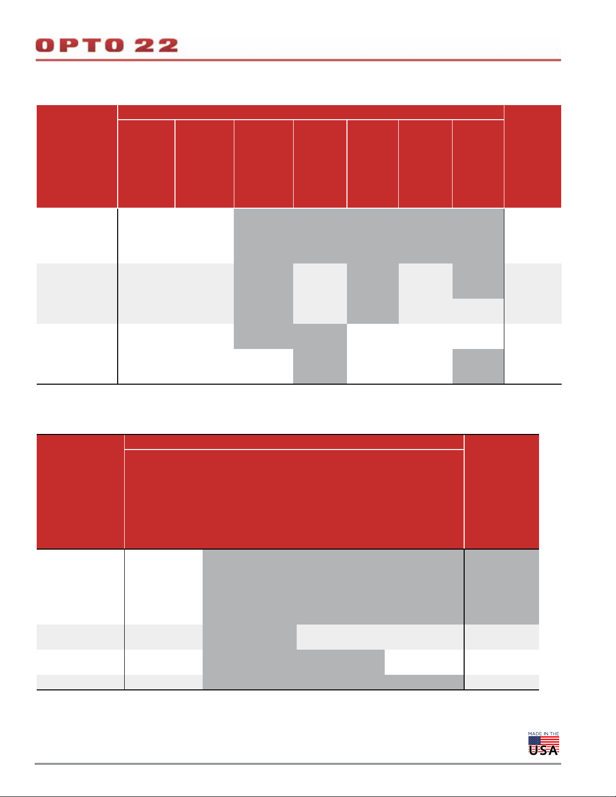
MODULE, BREAKOUT BOARD, AND CABLE COMPATIBILITY CHARTS
Find your module in the left column. Choose the breakout board from the right columns. Compatible cables are shown in the table cells in the
center.
4-Point Digital Modules
Breakout Board
Module
Digital input modules—4-point
SNAP-IAC5
SNAP-IAC5A
SNAP-IAC5AFM
SNAP-IAC5FM
SNAP-IAC5MA
SNAP-IDC5MA
SNAP-IDC5
SNAP-IDC5-FAST-A
SNAP-IDC5-HT
SNAP-IDC5D
SNAP-IDC5DFM
SNAP-IDC5FAST
SNAP-IDC5FM
SNAP-IDC5G
SNAP-IDC5Q SNAP-TEX-CBS6 Not used Not used for inputs
SNAP-IDC5-SW
SNAP-IDC5-SW-NC
Digital output modules—4-point
SNAP-ODC5-I
SNAP-ODC5-IFM
SNAP-ODC5A-I
SNAP-ODC5A-IFM
SNAP-ODC5MA
SNAP-OAC5-I
SNAP-OAC5-IFM
SNAP-OAC5MA
SNAP-ODC5SRC
SNAP-ODC5SRCFM
SNAP-OAC5
SNAP-OAC5FM
SNAP-ODC5ASNK
SNAP-ODC5R
SNAP-ODC5R5
SNAP-ODC5R5FM
SNAP-ODC5RFM
SNAP-ODC5SNK
SNAP-ODC5SNKFM
SNAP-OMR6T-C
SNAP-OMR6-C
* This cable maintains channel-to-channel isolation on these modules. If channel-to-channel
isolation is not important, you can also use the SNAP-TEX-CBO6 cable.
** The SNAP-TEX-32 can be used with digital outputs but has no fuses. SNAP-TEX-FB16
boards are preferable for digital outputs because they include fuses.
SNAP-TEX-32 **
SNAP-TEX-CBS6 * SNAP-TEX-CBS6 * Not used for inputs
SNAP-TEX-CBE6
SNAP-TEX-CBO6
SNAP-TEX-CBS6
SNAP-TEX-CBS6 Not used Not used for inputs
SNAP-TEX-CBS6 * SNAP-TEX-CBS6 *
SNAP-TEX-CBS6 * SNAP-TEX-CBS6 * Not used
SNAP-TEX-CBO6
SNAP-TEX-CBS6
SNAP-TEX-CBE6
SNAP-TEX-CBO6
SNAP-TEX-CBS6
Not used Not used Not used
SNAP-TEX-FB16-H
SNAP-TEX-FB16-L
SNAP-TEX-CBO6
SNAP-TEX-CBS6
SNAP-TEX-CBO6
SNAP-TEX-CBS6
SNAP-TEX-CBO6
SNAP-TEX-CBS6
SNAP-TEX-MR10-4
SNAP-TEX-MR10-16
SNAP-TEX-MR10-16C
Not used for inputs
SNAP-TEX-CBO6
SNAP-TEX-CBS6
SNAP-TEX-CBO6
SNAP-TEX-CBS6
Not used
OPTO 22 •
© 2008–2020 Opto 22. All rights reserved. Dimensions and specifications are subject to change. Brand or product names used herein are trademarks or registered trademarks of their respective companies or organizations.
Page 3
DA T A SHEET
Form 1756-200206
PAGE 3
MODULE, BREAKOUT BOARD, AND CABLE COMPATIBILITY CHARTS (CONTINUED)
Find your module in the left column. Choose the breakout board from the right columns. Compatible cables are shown in the table cells in the
center.
1-, 2-, and 4-Point Analog Modules
Breakout Board
Module
SNAP-TEX-32
SNAP-TEX-FB16-H
SNAP-TEX-FB16-L
Analog input modules (not thermocouples)
SNAP-AIARMS
SNAP-AIARMS-i
SNAP-AIARMS-i-FM
SNAP-AICTD
SNAP-AICTD-4
SNAP-AILC
SNAP-AILC-2
a
a
SNAP-AIMA-i
SNAP-AIMA-iSRC
a
SNAP-AIMA-iSRC-FM
SNAP-AIMA-iH
SNAP-AIRATE
SNAP-AIRATE-HFi
SNAP-AIRTD
SNAP-AIRTD-10
SNAP-AIRTD-1K
SNAP-AIV-72
SNAP-AIV-i
SNAP-AIV2-i
SNAP-AIVRMS
SNAP-AIVRMS-i
a
SNAP-AIVRMS-i-FM
SNAP-TEX-CBS6 Not used for analog modules
SNAP-AIMA2-i
SNAP-AIMA
SNAP-AIMA-4
SNAP-AIMV2-4
SNAP-AIR40K-4
SNAP-AIV
SNAP-AIV-4
SNAP-TEX-CBE6
SNAP-TEX-CBS6
Not used for analog modules
SNAP-AIMV-4
SNAP-AIPM
SNAP-AIPM-3
SNAP-AIPM-3V
SNAP-AITM
c
SNAP-AITM-i
b
SNAP-AITM-2
SNAP-AITM-4i
SNAP-AITM2-i
c
SNAP-pH/ORP
c
c
c
No cable available Not used for analog modules
Analog output modules
SNAP-AOA-23 SNAP-AOA-28
SNAP-TEX-CBE6
SNAP-TEX-CBS6
Not used for analog modules
SNAP-TEX-CBE6
SNAP-AOA-3 SNAP-AOV-5
SNAP-TEX-CBO6
Not used for analog modules
SNAP-TEX-CBS6
SNAP-AOV-25 SNAP-AOV-27 SNAP-TEX-CBO6 Not used for analog modules
SNAP-AOA-23-iH
SNAP-AOA-23-iSRC
SNAP-AOA-23-iSRC-FM
SNAP-AOD-29
a
SNAP-AOD-29-HFi
a
SNAP-TEX-CBS6 Not used for analog modules
a Note that the SNAP-TEX-SBS6 cable does not include a connector for the 2-pin terminal on top of these modules,
required for excitation voltage.
b Not recommended for use with breakout boards due to CT safety concerns.
c Do not use breakout boards with thermocouples.
SNAP-TEX-MR10-4
SNAP-TEX-MR10-16
SNAP-TEX-MR10-16C
OPTO 22 •
© 2008–2020 Opto 22. All rights reserved. Dimensions and specifications are subject to change. Brand or product names used herein are trademarks or registered trademarks of their respective companies or organizations.
Page 4
High-Density Digital Modules
Module
DA T A SHEET
Form 1756-200206
PAGE 4
Breakout Board
Without a
breakout
board
SNAP-IAC-16
SNAP-IAC-A-16
SNAP-IAC-K-16
SNAP-IDC-16
SNAP-IDC-HT-16
SNAP-IDC-32
SNAP-IDC-32-FM
SNAP-IDC-32D
SNAP-IDC-32N
SNAP-IDC-32DN
SNAP-ODC-32-SNK
SNAP-ODC-32-SNK-FM
SNAP-ODC-32-SRC
SNAP-ODC-32-SRC-FM
SNAP-TEX-32
SNAP-HD-ACF6
(2 modules/
board)
SNAP-HD-CBF6
SNAP-HD-CBF6
SNAP-TEX-FB16-H
SNAP-TEX-FB16-L
SNAP-HD-ACF6
SNAP-HD-CBF6
(2 boards/
module)
SNAP-HD-CBF6
(2 boards/
module)
SNAP-TEX-MR10-4
SNAP-TEX-MR10-16
SNAP-TEX-MR10-16C
Not used with
inputs
Not used with
inputs
Do not use Not used
SNAP-HD-CBF6
SNAP-HD-G4F6
(MR10-16C only)
Not used Not used Not used Not used
SNAP-HD-BF6
Not used Not used
SNAP-IDC-HDB
SNAP-IDC-HDB-FM
SNAP-ODC-HDB
Not used
SNAP-HD-BF6 SNAP-HD-BF6
SNAP-ODC-HDB-FM
SNAP-UDC-HDB
SNAP-HD-BF6
SNAP-UDC-HDB-G4
SNAP-HD-ACF6
Not used
SNAP-HD-CBF6
SNAP-HD-BF6
SNAP-HD-BF6
SNAP-HD-CBF6
Analog Modules with More Than 4 Points
Breakout Board
SNAP-TEX-FB16-H
SNAP-TEX-FB16-L
SNAP-TEX-MR10-4
Module
SNAP-AICTD-8
SNAP-AIMA-8
SNAP-AIR400K-8
SNAP-AIRTD-8U
SNAP-AITM-8 **
SNAP-AITM-8-FM **
SNAP-AIV-8
SNAP-AIMA-32
SNAP-AIMA-32-FM
SNAP-AIV-32
SNAP-AIV-32-FM
SNAP-AOVA-8 SNAP-HD-20F6 Not used SNAP-HD-20F6
* For specific applications. See details in wiring diagrams.
** Do not use breakout boards with thermocouples.
SNAP-TEX-32
Can be used;
no cable currently
available
Not recommended SNAP-HD-BF6 SNAP-HD-BF6* Not recommended
SNAP-HD-CBF6 Not used SNAP-HD-BF6 SNAP-HD-CBF6
SNAP-TEX-MR10-16
SNAP-TEX-MR10-16C
SNAP-IDC-HDB
SNAP-IDC-HDB-FM
SNAP-ODC-HDB
SNAP-ODC-HDB-FM
Not used with analog
modules
SNAP-AIMA-HDB
SNAP-AIMA-HDB-FM
Not used No cable available
SNAP-AIV-HDB
SNAP-AIV-HDB-FM
Without a
breakout board
OPTO 22 •
© 2008–2020 Opto 22. All rights reserved. Dimensions and specifications are subject to change. Brand or product names used herein are trademarks or registered trademarks of their respective companies or organizations.
Page 5
DA T A SHEET
Form 1756-200206
CABLES FOR 1-, 2-, OR 4-PT MODULES: SNAP-TEX-CBO6, SNAP-TEX-CBE6, SNAP-TEX-CBS6
PAGE 5
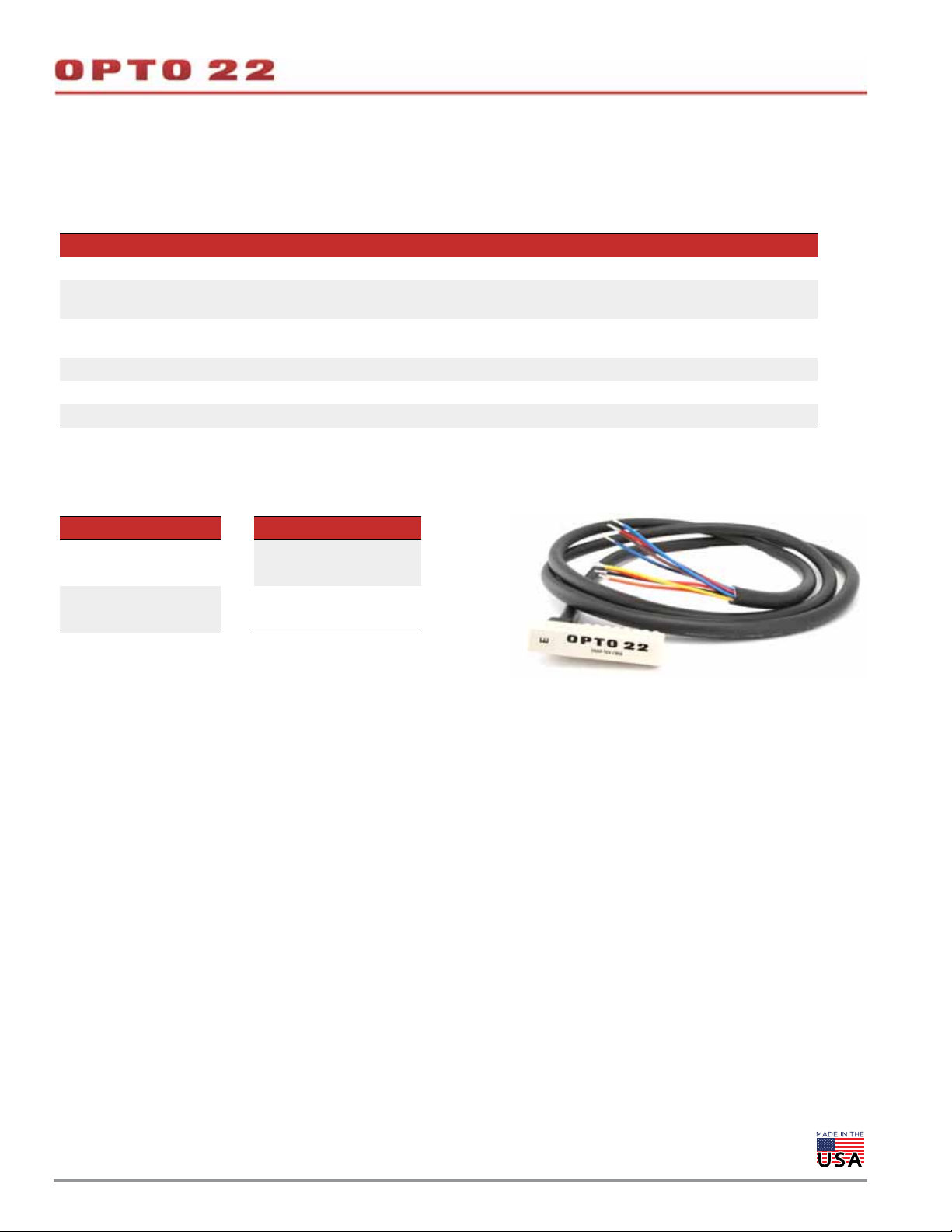
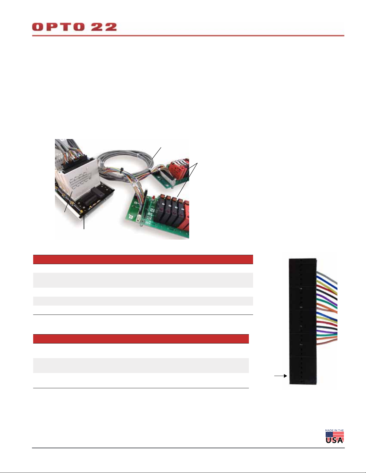
These three cables provide neat, protected wiring from the top of a 1-,
2-, or 4-point module to the breakout board. Each cable snaps into the
top of one module and terminates at the breakout board with
18-gauge, color-coded flying leads, already stripped and tinned and
ready for wiring. The leads attach easily to the breakout board with
spring connectors.
SNAP-TEX-CBO6—Odd-numbered terminals are commoned.
SNAP-TEX-CBE6—Even-numbered terminals are commoned.
SNAP-TEX-CBS6—No common terminals; wiring is straight through.
See the tables starting on page 2 to determine the correct cable for
your module and breakout board.
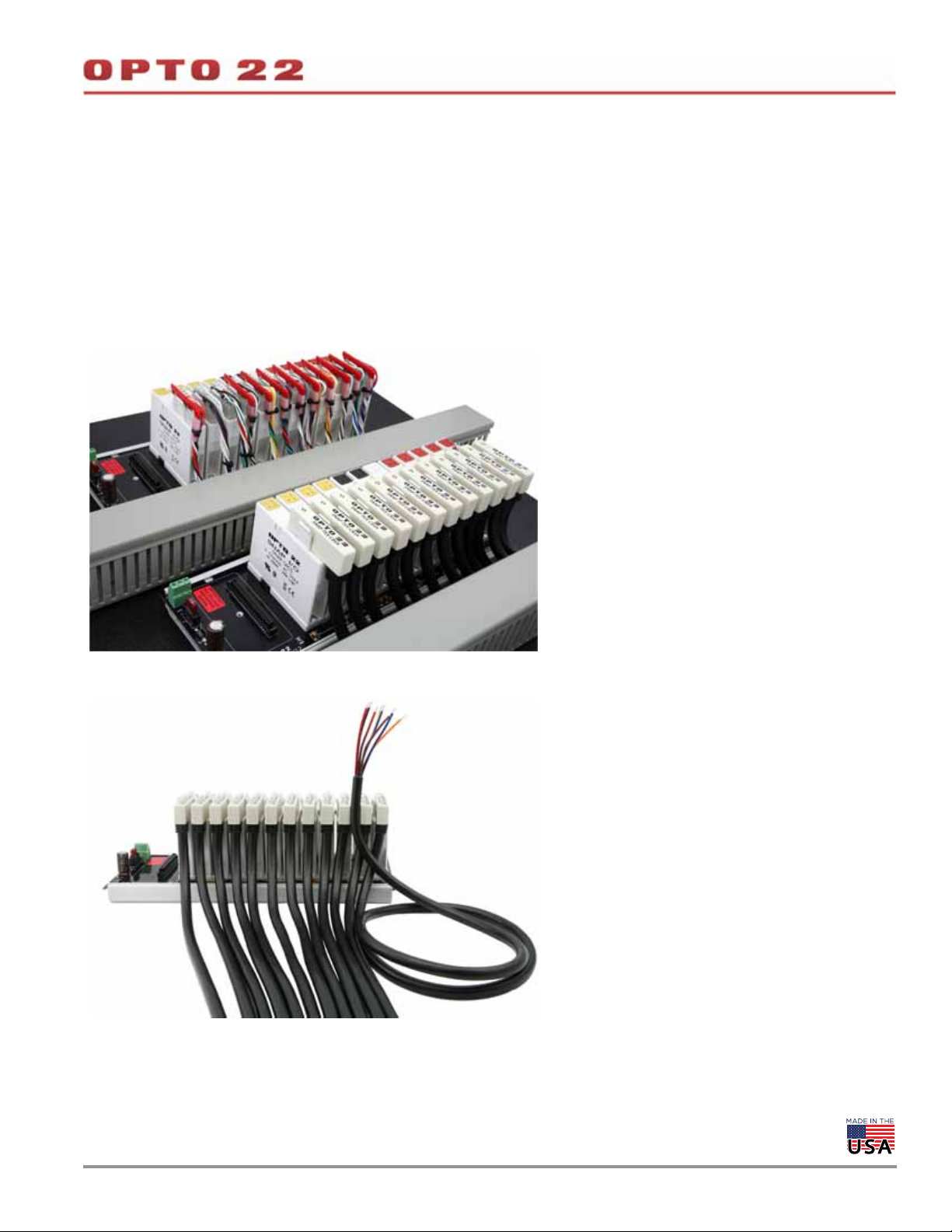
This photo shows the contrast between a regularly wired
SNAP PAC rack (at upper left) and one using SNAP-TEX-CBE6,
-CBO6, and -CBS6 cables (at lower right).
The cables protect top-of-module connections and wires,
and make it easier to follow wiring to field devices.
OPTO 22 •
Cables terminate in color-coded flying leads, already stripped,
tinned, and ready for wiring.
Installation, maintenance, and troubleshooting are faster and
simpler using SNAP TEX cables.
© 2008–2020 Opto 22. All rights reserved. Dimensions and specifications are subject to change. Brand or product names used herein are trademarks or registered trademarks of their respective companies or organizations.
Page 6
CABLES FOR 1-, 2-, OR 4-POINT MODULES (CONTINUED)
Cable Specifications
See the tables starting on page 2 for module, cable, and breakout board compatibility.
Feature SNAP-TEX-CBO6 SNAP-TEX-CBE6 SNAP-TEX-CBS6
Cable length 6 feet (1.8 meters) 6 feet (1.8 meters) 6 feet (1.8 meters)
Connector
Wires
Bussing Odd-numbered pins connected Even-numbered pins connected* No connections
Agency Approvals CE, RoHS, DFARS CE, RoHS, DFARS CE, RoHS, DFARS
Warranty 30 months 30 months 30 months
*Do NOT USE the CBE6 with a SNAP-TEX-FB16-H or -L breakout board. The FB16s have odd-numbered pins connected.
8 pins, 0.2 in. (5.08 mm) center-to-center
8 pre-stripped, tinned,
color-coded, 18 gauge
Wire Colors
8 pins, 0.2 in. (5.08 mm) center-to-center
8 pre-stripped, tinned, color-coded,
18 gauge
8 pins, 0.2 in. (5.08 mm) center-to-center
8 pre-stripped, tinned, color-coded,
18 gauge
DA T A SHEET
Form 1756-200206
PAGE 6
Point Pin Color wire Point Pin Color wire
1 black
0
2 red 6 brown
3 blue
1
4 orange 8 blue/black
2
3
5 yellow
7 red/black
Wiring diagrams begin on page 24.
OPTO 22 •
© 2008–2020 Opto 22. All rights reserved. Dimensions and specifications are subject to change. Brand or product names used herein are trademarks or registered trademarks of their respective companies or organizations.
Page 7
CABLE FOR 8-POINT ANALOG OUTPUT MODULE: SNAP-HD-20F6
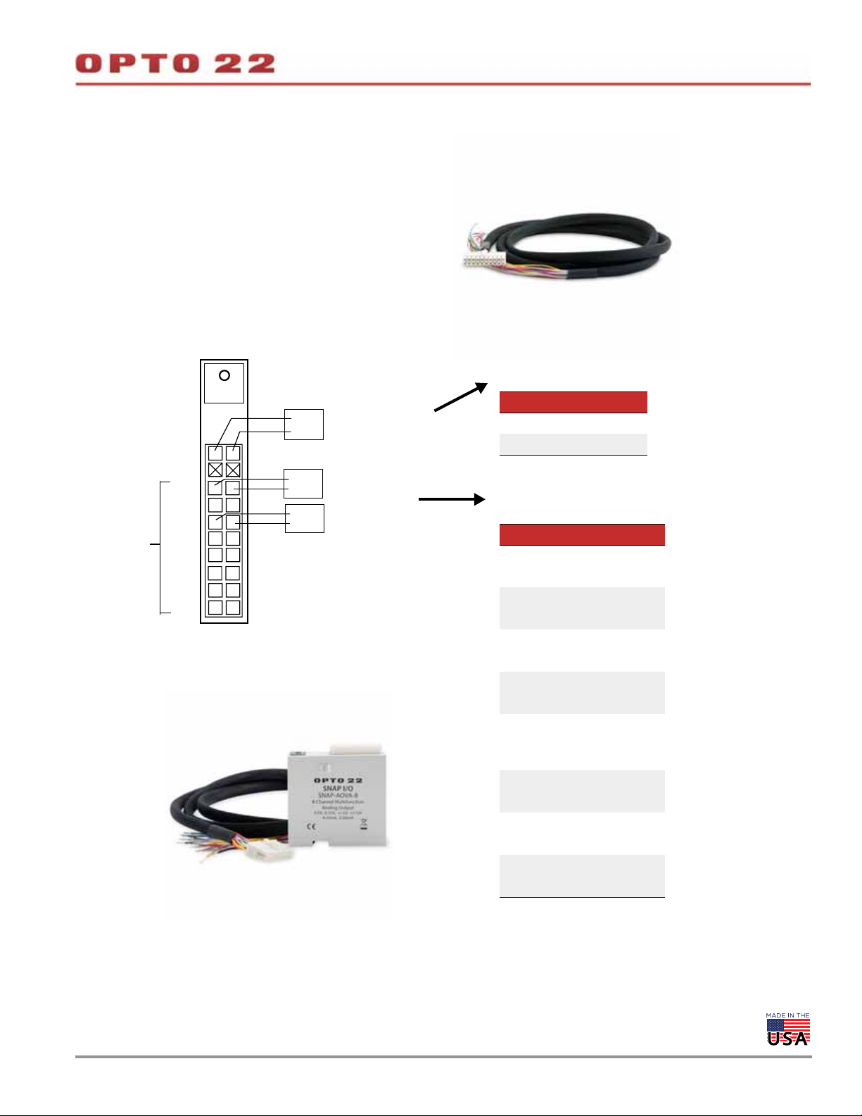
The SNAP-HD-20F6 cable is designed for use with an
8-channel SNAP-AOVA-8 analog output module. The cable
has a 20-pin connector at the module end and flying leads
for field wiring.
You can also use the cable and module with a SNAP-TEX-32
breakout board (four modules per board). See page 32 for a
wiring diagram.
DA T A SHEET
Form 1756-200206
PAGE 7
NAP-AOVA-8 Module (from top)
LED - indicates excitation
–
+
24 VDC excitation
Outputs
Not used
Ch 0
Ch 1
Ch 2
Ch 3
Ch 4
Ch 5
Ch 6
Ch 7
+
–
For more information on the SNAP-AOVA-8 module, see
the SNAP Analog Output Modules Data Sheet (form 1066).
–
+
–
+
All negative output terminals are tied
together internally.
All current from any output is sourced
from the module. No external
excitation supplies allowed.
24 VDC Power Supply
This supply is isolated
from the module outputs.
Current input
Voltage input
SNAP-HD-20F6 Cable
Wire colors - Excitation
24 VDC Color
– Black
+ White with Black
Wire colors - Output points
Ch –/+ Color
– Blue
0
+ White with Blue
– Pink
1
+ White with Pink
– Gray
2
+ White with Gray
– Green
3
+ White with Green
– Orange
4
5
6
7
NOTE: Yellow with purple and
purple with yellow wires are not used.
White with
+
Orange
– Red
+ White with Red
– Purple
+ White with Purple
– Yellow
+ White with Yellow
OPTO 22 •
© 2008–2020 Opto 22. All rights reserved. Dimensions and specifications are subject to change. Brand or product names used herein are trademarks or registered trademarks of their respective companies or organizations.
Page 8
DA T A SHEET
Form 1756-200206
PAGE 8
CABLES FOR 16- OR 32-POINT MODULES: SNAP-HD-ACF6, SNAP-HD-CBF6, SNAP-HD-BF6
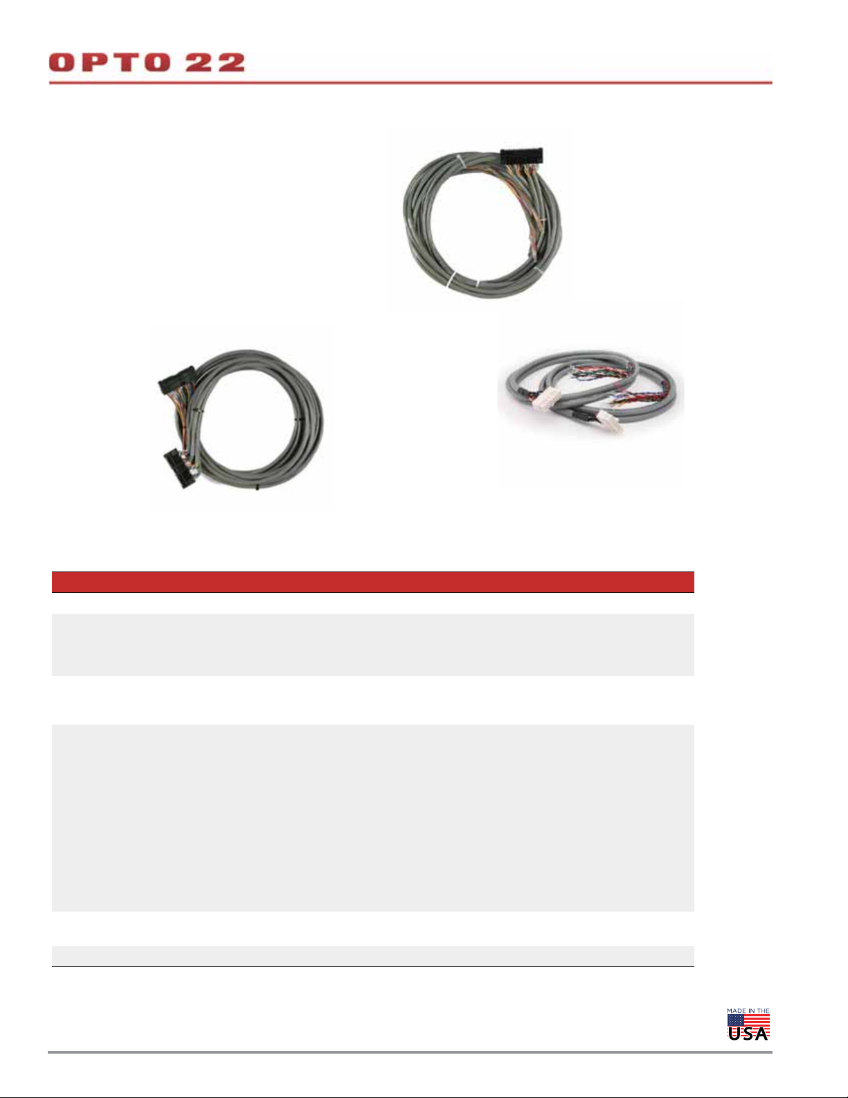
The SNAP-HD-ACF6, SNAP-HD-CBF6, and SNAP-HD-BF6
cables connect 16- and 32-channel modules to field wiring
or breakout boards. Each cable is 6 ft. (1.8 m) long.
The SNAP-HD-ACF6 and the SNAP-HD-CBF6 have
connectors at one end that attach to the top of a module and
flying leads at the other end for field wiring. The ACF6 is for
16-channel modules and includes two cables, each cable
wiring 8 channels. The CBF6 is for 32-channel modules.
The SNAP-HD-BF6 has connectors at both ends, one for a
32-channel module and the other for a suitable breakout
rack.
SNAP-HD-CBF6
SNAP-HD-BF6
SNAP-HD-ACF6
Cable Specifications
See tables starting on page 2 for detailed module, cable, and breakout board compatibility. Wiring diagrams begin on page 24.
Feature SNAP-HD-ACF6 SNAP-HD-CBF6 SNAP-HD-BF6
Cable length 6 feet (1.8 meters) 6 feet (1.8 meters) 6 feet (1.8 meters)
Two-cable assembly;
Connectors
Wires
Use with
Agency
Approvals
Warranty 30 months 30 months 30 months
* Special application; see wiring diagrams.
16-pin connector at
module end; flying
leads at other end
Pre-stripped, tinned,
color-coded, 22-gauge
wires
Modules:
SNAP-IAC-16
SNAP-IAC-A-16
SNAP-IAC-K-16
SNAP-IDC-16
SNAP-IDC-HT-16
CE, RoHS, DFARS CE, RoHS, DFARS CE, RoHS, DFARS
One 40-pin connector at
module end; flying leads at
other end
Pre-stripped, tinned,
color-coded, 24-gauge
wires
Modules:
SNAP-IDC-32
SNAP-IDC-32-FM
SNAP-IDC-32N
SNAP-IDC-32D
SNAP-IDC-32DN
SNAP-ODC-32-SNK
SNAP-ODC-32-SNK-FM
SNAP-ODC-32-SRC
SNAP-ODC-32-SRC-FM
SNAP-AIV-32
SNAP-AIV-32-FM
One connector at module end; one connector at
breakout board end
24-gauge wires
Modules to breakout boards (regular and -FM versions):
SNAP-IDC-32 to SNAP-IDC-HDB or SNAP-UDC-HD
SNAP-IDC-32N to SNAP-IDC-HDB, SNAP-UDC-HDB,
or SNAP-UDC-HDB-G4
SNAP-IDC-32D to SNAP-IDC-HDB or SNAP-UDC-HDB
SNAP-IDC-32DN to SNAP-IDC-HDB, SNAP-UDC-HDB,
or SNAP-UDC-HDB-G4
SNAP-ODC-32-SNK to SNAP-ODC-HDB, SNAP-UDC-HDB,
or SNAP-UDC-HDB-G4
SNAP-ODC-32-SRC to SNAP-ODC-HDB or SNAP-UDC-HDB
SNAP-AIV-32 to SNAP-AIV-HDB
SNAP-AIMA-32 to SNAP-AIMA-HDB
SNAP-AIMA-32 to SNAP-AIV-HDB*
OPTO 22 •
© 2008–2020 Opto 22. All rights reserved. Dimensions and specifications are subject to change. Brand or product names used herein are trademarks or registered trademarks of their respective companies or organizations.
Page 9
CABLES TO CONNECT G4 TO SNAP: SNAP-HD-G4F6, SNAP-HD-G4F6N
The SNAP-HD-G4F6 and cables are used to connect a SNAP
high-density digital (HDD) module to G4 mounting racks in order to
integrate older G4 (or even G1) digital output systems with modern
PAC Project software and SNAP PAC Ethernet-based controllers.
Each cable connects two 16-channel mounting racks to one 32-point
digital module. Cables can also be used to connect G1 mounting
racks with header connectors to these modules. See the table below
for module and rack compatibility.
DA T A SHEET
Form 1756-200206
PAGE 9
For outputs, this connection makes available the G4 output’s up to
3-amp switching and sensing capability, which can provide twelve
times the 0.25 amp capability of the HDD modules themselves. (For
G4 module specs, see Opto 22 form #727, the G4 Digital I/O Data
Book.)
NOTE: For another option, see the SNAP-UDC-HDB-G4 on page 20.
The SNAP-HD-G4F6 cable can also be used to connect two
SNAP-TEX-MR10-16C breakout boards to one 32-point digital module.
See “Breakout Boards with Mechanical Relays: SNAP-TEX-MR10-4,
SNAP-TEX-MR10-16, and SNAP-TEX-MR10-16C” on page 13.
For more information on HDD modules, see the SNAP High-Density
Digital Module Data Sheet (form 1556).
SNAP-HD-G4F6 header cable
G4PB16H mounting racks
In this photo, the SNAP-HD-G4F6 header cable connects a single
SNAP-ODC-32-SNK digital output module on a SNAP PAC mounting rack to
two G4PB16H mounting racks.
NOTE: Do not use this cable with a SNAP-ODC-32-SRC module when
connecting to G4 mounting racks.
SNAP-ODC-32-SNK
module
NOTE: If there is a mismatch between the cable connector and the header
connector, please contact Opto 22 Product Support.
SNAP mounting rack
Cable Specifications
Feature SNAP-HD-G4F6 SNAP-HD-G4F6N
Cable length 6 feet (1.8 meters) 6 feet (1.8 meters)
Connectors
Use with 32-point digital output modules 32-point digital input modules
Agency approvals CE, RoHS, DFARS CE, RoHS, DFARS
Warranty 30 months 30 months
One connector at module end; two
header connectors at rack end
One connector at module end; two
header connectors at rack end
SNAP-HD-G4F6 cable
Compatible Modules and Racks
Cable Modules Racks Integrated I/O
SNAP-HD-G4F6
SNAP-HD-G4F6N
* For 15 volt or 24 volt G1 or G4 modules, use the SNAP-IDC-32N.
For 5 volt modules, use the SNAP-IDC-32DN.
SNAP-ODC-32-SNK
SNAP-ODC-32-SNK-FM
SNAP-IDC-32N*
SNAP-IDC-32DN*
NOTE: While not designed for this use, it is possible to connect the SNAP-IDC-32 module with G4 15 or 24 V inputs using a SNAP-HD-G4F6 cable.
However, the SNAP-IDC-32 uses positive-true logic and therefore returns the inverse of the typical negative-true logic. For example, if the SNAP-IDC-32
is controlled by a PAC Control strategy, an “OFF” state from it actually indicates that the associated G4 module is turned ON.
OPTO 22 •
© 2008–2020 Opto 22. All rights reserved. Dimensions and specifications are subject to change. Brand or product names used herein are trademarks or registered trademarks of their respective companies or organizations.
G4PB16H
G4PB16HC
G4PB16H
G4PB16HC
PB16H
PB16HC
PB16H
PB16HC
G4PB16L PB16L
–
Pin 1
Page 10
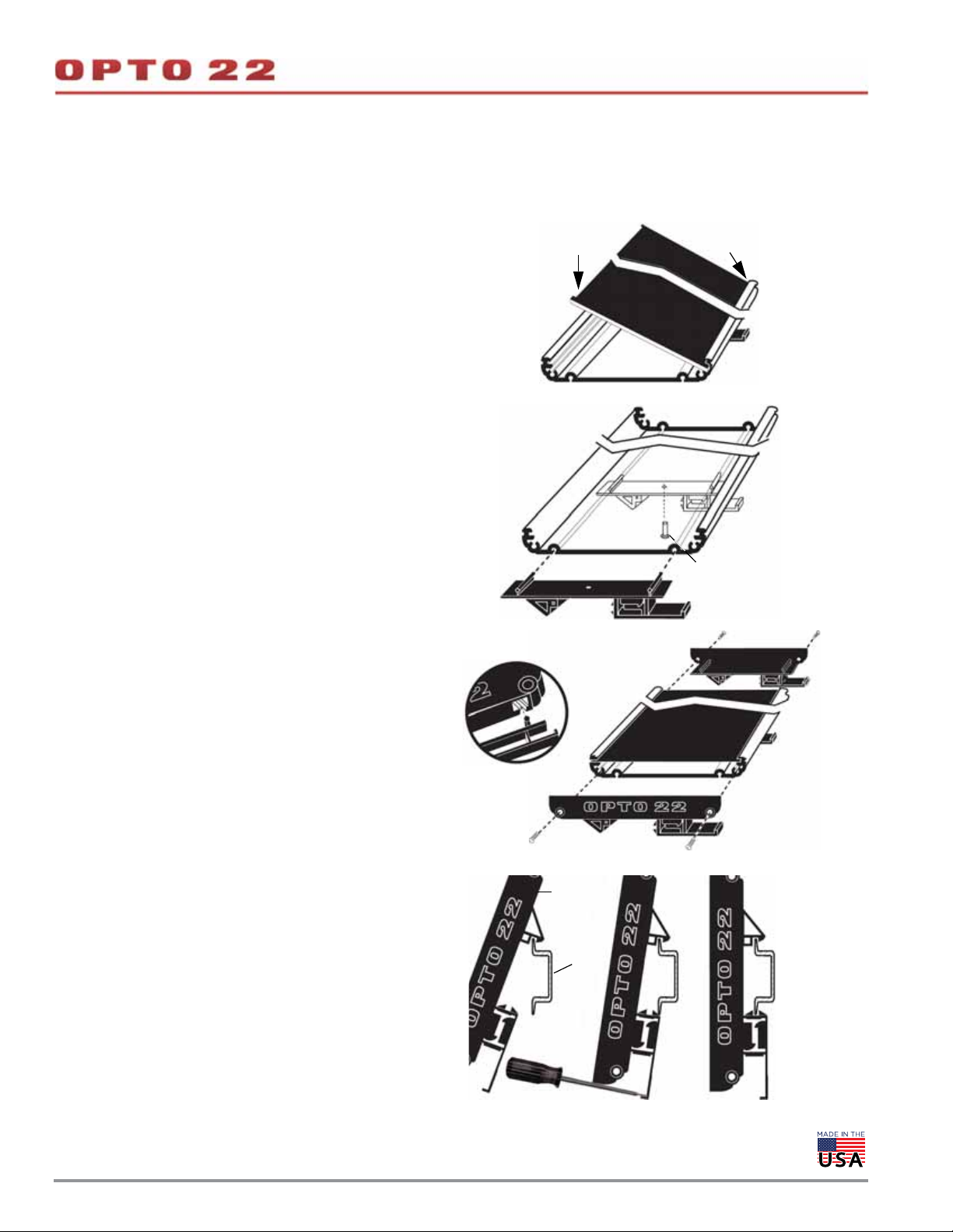
BREAKOUT BOARDS—A SSEMBLY AND INSTALLA TION
All breakout boards that come with a plastic extrusion can be panel
mounted or DIN-rail mounted. DIN-rail clips are sold separately; see the
SNAP TEX Mounting/Wiring Tools Data Sheet (form 1772).
DA T A SHEET
Form 1756-200206
PAGE 10
CAUTION: D
o not let cutting fluids, cleaners, lubricants, or other chemicals
contact the plastic extrusion, as they can cause cracking. If you use these
chemicals before rack installation, be sure they are thoroughly cleaned off.
Panel mounting
1. Place the extrusion in position on the panel and mount it
using the holes provided.
2. Insert one edge of the circuit board into the extrusion.
DIN-rail mounting
1. For boards that use three or more DIN-rail clips: slide one
DIN clip to the middle position and secure with the rivet
provided. For racks with four clips, add an additional
middle clip.
2. Insert one edge of the circuit board into the extrusion.
3. Push down hard on the other edge to snap the board
into place.
4. Attach one DIN clip to each end cap using the slots in
the end caps as shown.
5. Using the screws provided, secure an end cap and DIN
clip assembly to each end of the extrusion.
4
3
2
1
Rivet
(included)
Removing the Circuit Board from the Rack
Extrusion
If end caps are present, remove them. Then insert a flathead
screwdriver in one of the circuit board release notches and pry
up the board. Repeat in the other release notches until the
board pops out of the extrusion.
Attaching the Adapter Clip to a DIN Rail
1. Hook the DIN-rail clip over the top of the DIN rail.
2. Using a screwdriver, pry open the DIN-rail clip flange at
the bottom of the clip. Push the clip toward the DIN rail.
3. Snap the DIN-rail clip into place
5
Extrusion
assembly
DIN rail
OPTO 22 •
© 2008–2020 Opto 22. All rights reserved. Dimensions and specifications are subject to change. Brand or product names used herein are trademarks or registered trademarks of their respective companies or organizations.
Page 11
BREAKOUT BOARDS: SNAP-TEX-32, SNAP-TEX-FB16-H, SNAP-TEX-FB16-L
DA T A SHEET
Form 1756-200206
PAGE 11
The SNAP-TEX-32 is a simple breakout board with straight-through
wiring. Designed primarily for 2- and 4-point analog inputs/outputs
and for 4-point digital inputs, the breakout board is used with
CAUTION: Odd pins on the SNAP-TEX-FB16-H and SNAP-TEX-FB16-L
breakout boards are commoned. Use only straight-through or odd cables
with these boards.
SNAP-TEX cables. The board can be used with digital outputs, but it
does not have fuses.
The SNAP-TEX-32 can also be used with 8-, 16-, or 32-point SNAP
analog modules (not thermocouples). See the table beginning on
page 2 for recommended cable and board combinations for your
modules.
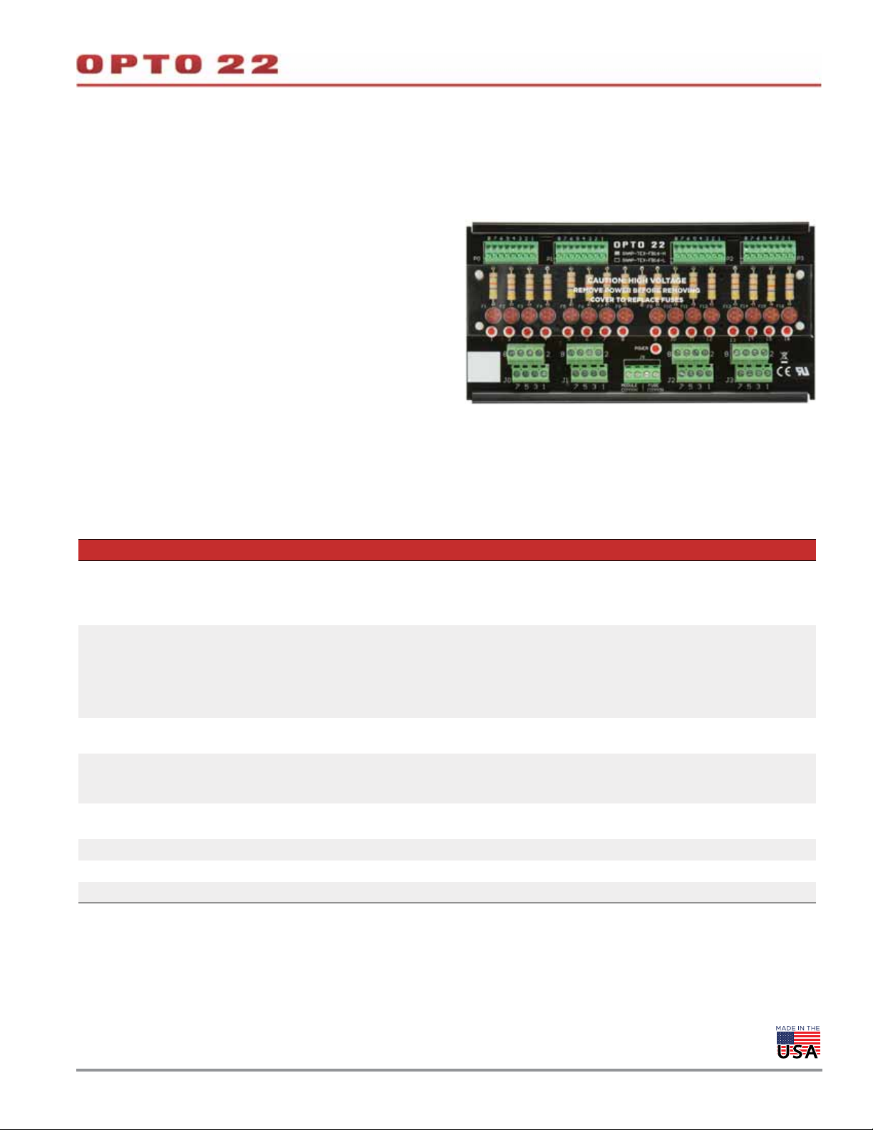
The SNAP-TEX-FB16-H and SNAP-TEX-FB16-L breakout boards
provide a fuse and a fuse-blown indicator for each of their 16
channels. In addition, they provide power to loads: the
SNAP-TEX-F16-H provides 120–240 volts, and the SNAP-TEX-F16-L
provides 12–24 volts. Simply attach the power source to a single spot
in the middle of the rack, and power goes out to solenoids or
switches, depending on the module you’re using. These breakout
boards are used primarily for digital inputs and outputs.
SNAP-TEX-FB16-H
Specifications
See the table beginning on page 2 for recommended cable and board combinations. Wiring diagrams begin on page 24.
Feature SNAP-TEX-32 SNAP-TEX-FB16-H SNAP-TEX-FB16-L
2- or 4-point analog inputs/outputs;
Use with I/O
modules
Use with cables
Connectors
Fusing none
Indicators none
Bussed power none 120–240 V 12–24 V
Agency Approvals CE, RoHS, DFARS UL, CE, RoHS, DFARS UL, CE, RoHS, DFARS
Warranty 30 months 30 months 30 months
* Can be used with digital outputs but does not have fuses. SNAP-TEX-FB16 boards have fuses; they are better for digital outputs.
** IMPORTANT: Do NOT USE the FB16 breakout boards with a SNAP-TEX-CBE6 cable. The board has odd pins connected; the cable has even
pins connected.
4-point digital inputs/outputs*; 8-, 16-,
or 32-point digital and analog outputs
(not thermocouples)
SNAP-TEX-CBE6 (even pins con-
nected), SNAP-TEX-CBO6 (odd pins
connected), or SNAP-TEX-CBS6 (no
connections), depending on module.
SNAP-HD-20F6 with a SNAP-AOVA-8
module.
32 spring connectors; accommodates
eight 4-point modules
4-point digital inputs and outputs
16- and 32-pt digital inputs/outputs
4-ch modules: SNAP-TEX-CBO6 (odd
pins connected)** or SNAP-TEX-CBS6
(straight-through), depending on module.
16-ch modules: SNAP-HD-ACF6
32-ch modules: SNAP-HD-CBF6
16 spring connectors; accommodates
four 4-point modules
1 A, 250 V, fast-acting fuse for each I/O
point (16 total). Replace with Opto 22 PN
FUSE01G4
1 blown-fuse LED per fuse
(16 LEDs total)
OPTO 22 •
© 2008–2020 Opto 22. All rights reserved. Dimensions and specifications are subject to change. Brand or product names used herein are trademarks or registered trademarks of their respective companies or organizations.
Page 12
Form 1756-200206
BREAKOUT BOARDS: SNAP-TEX-32, SNAP-TEX-FB16-H, SNAP-TEX-FB16-L (CONTINUED)
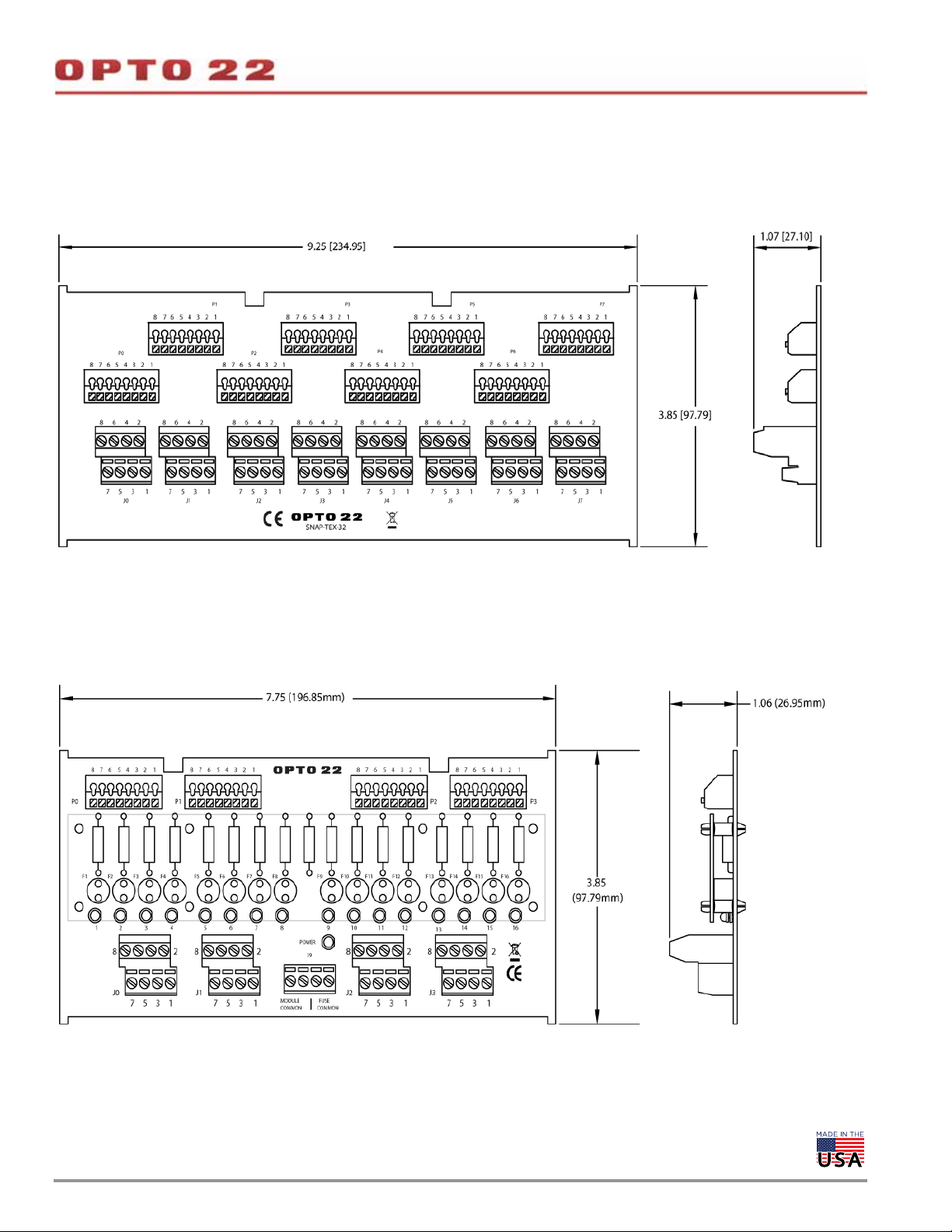
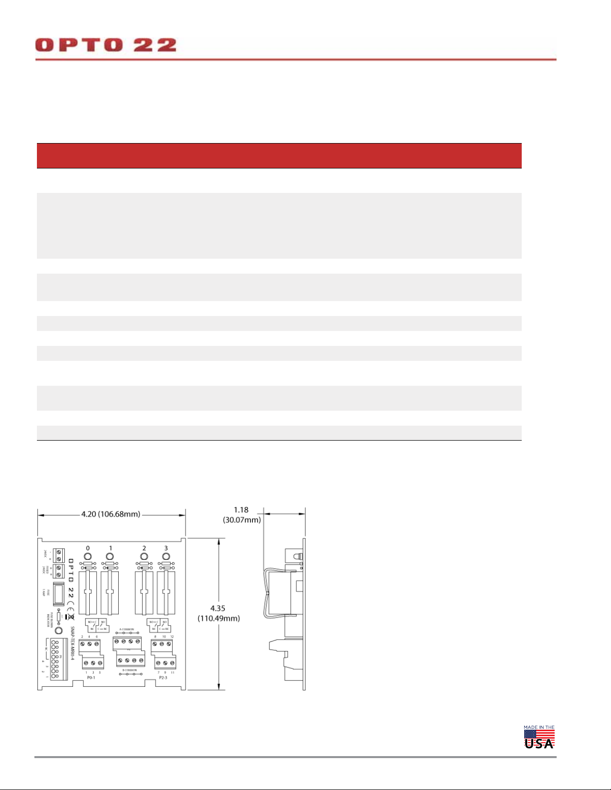
Dimensions—SNAP-TEX-32 Breakout Board
Dimensions are shown in inches (with centimeters in parentheses).
DA T A SHEET
PAGE 12
Dimensions—SNAP-TEX-FB16-H and SNAP-TEX-FB16-L Breakout Boards
Dimensions are shown in inches (with centimeters in parentheses).
OPTO 22 •
© 2008–2020 Opto 22. All rights reserved. Dimensions and specifications are subject to change. Brand or product names used herein are trademarks or registered trademarks of their respective companies or organizations.
Page 13
DA T A SHEET
Form 1756-200206
PAGE 13
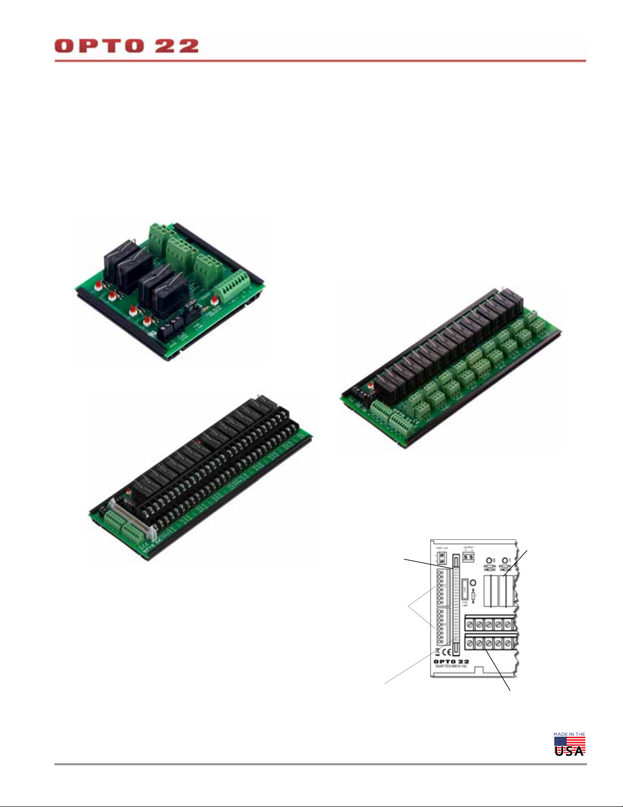
BREAKOUT BOARDS WITH MECHANICAL RELAYS: SNAP-TEX-MR10-4, SNAP-TEX-MR10-16,
AND SNAP-TEX-MR10-16C
The SNAP-TEX-MR10-4, SNAP-TEX-MR10-16, and SNAP-TEX-MR10-16C
breakout boards, designed for high-current switching, feature mechanical
relays that can switch up to 10 A per channel. (Standard SNAP output modules
can switch up to 0.75 A; SNAP-OMR6 output modules can switch up to 6 A.)
These breakout boards include on/off indicators for each channel,
and each channel can be wired for normally closed or normally open.
The boards require 24 VDC power. A replacement relay is available:
part number SNAP-MR10.
NOTE: Transient protection must be used on inductive loads.
SNAP-TEX-MR10-4
SNAP-TEX-MR10-16C
With the SNAP-TEX-MR10-16C, you can connect digital output
modules in two ways:
• Connect four standard 4-point ODC modules using the two
spring connectors and the appropriate cable for the modules
(see page 30).
• Connect one SNAP-ODC-32-SRC high-density module to the
header connectors on two MR10-16C breakout boards. Requires
a SNAP-HD-G4F6 cable (see page 50).
Also, bussed commons in 2-channel groups provide easier wiring
of loads. Bussing straps (STRAP2Q and STRAP4Q) can be used for
quick common power connections between relay groups (see
page 31).
SNAP-TEX-MR10-16
Pin 1 for header
connector
Spring connectors for
standard, 4-point
ODC modules
Header connector for high-density
SNAP-ODC-32-SRC module
Mechanical relays
Field connectors
OPTO 22 •
© 2008–2020 Opto 22. All rights reserved. Dimensions and specifications are subject to change. Brand or product names used herein are trademarks or registered trademarks of their respective companies or organizations.
Page 14
BREAKOUT BOARDS WITH MECHANICAL RELAYS (CONTINUED)
Specifications
See the tables beginning on page 2 for compatible modules and cables. Wiring diagrams begin on page 24.
DA T A SHEET
Form 1756-200206
PAGE 14
Feature
Use with I/O modules
Use with cables
Use with jumper straps – STRAP2Q, STRAP4Q
Relay contacts
Switching capacity 10 A @ 240 VAC 10 A @ 240 VAC
Switch On time 7 ms nominal 7 ms nominal
Switch Off time 3 ms nominal 3 ms nominal
Fusing 24 V fuse for board. Opto 22 p/n SNAP-FUSE1AC 24 V fuse for board. Opto 22 p/n SNAP-FUSE1AC
Indicators
Power requirements
(all positions On)
Agency Approvals UL, CE, RoHS, DFARS UL, CE, RoHS, DFARS
Warranty 30 months from date of manufacture 30 months from date of manufacture
SNAP-ODC5-i, SNAP-ODC5A-i,
SNAP-ODC5SRC, SNAP-ODC-32-SRC
SNAP-TEX-CBO6 (odd pins bussed),
SNAP-TEX-CBS6 (no bussing), or
SNAP-HD-CBF6, depending on module
SPDT (1 Form C)
Typical life expectancy (Electrical): 1 x 10
On/Off status indicators (one for each channel)
1 fuse-blown indicator
24 VDC @ 75 mA 24 VDC @ 300 mA
SNAP-TEX-MR10-4
SNAP-TEXMR10-16
SNAP-TEX-MR10-16C
SNAP-ODC5-i, SNAP-ODC5A-i,
SNAP-ODC5SRC, SNAP-ODC-32-SRC
• For one high-density SNAP-ODC-32-SRC module,
use a SNAP-HD-G4F6 cable to connect two breakout
boards to one module.
• For four 4-point modules, use SNAP-TEX-CBO6 (odd
pins bussed) or SNAP-TEX-CBS6 (no bussing),
depending on module.
5
SPDT (1 Form C)
Typical life expectancy (Electrical): 1 x 10
On/Off status indicators (one for each channel)
1 fuse-blown indicator
5
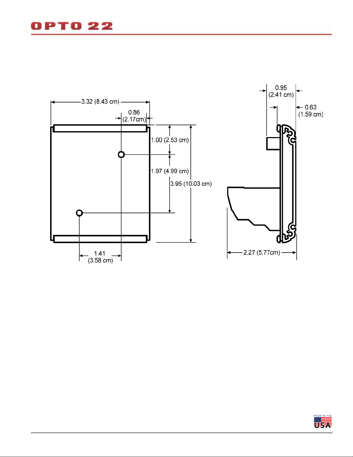
Dimensional Drawing—SNAP-TEX-MR10-4 Breakout Board
Dimensions are shown in inches (with centimeters in parentheses).
OPTO 22 •
© 2008–2020 Opto 22. All rights reserved. Dimensions and specifications are subject to change. Brand or product names used herein are trademarks or registered trademarks of their respective companies or organizations.
Page 15
BREAKOUT BOARD WITH MECHANICAL RELAYS (CONTINUED)
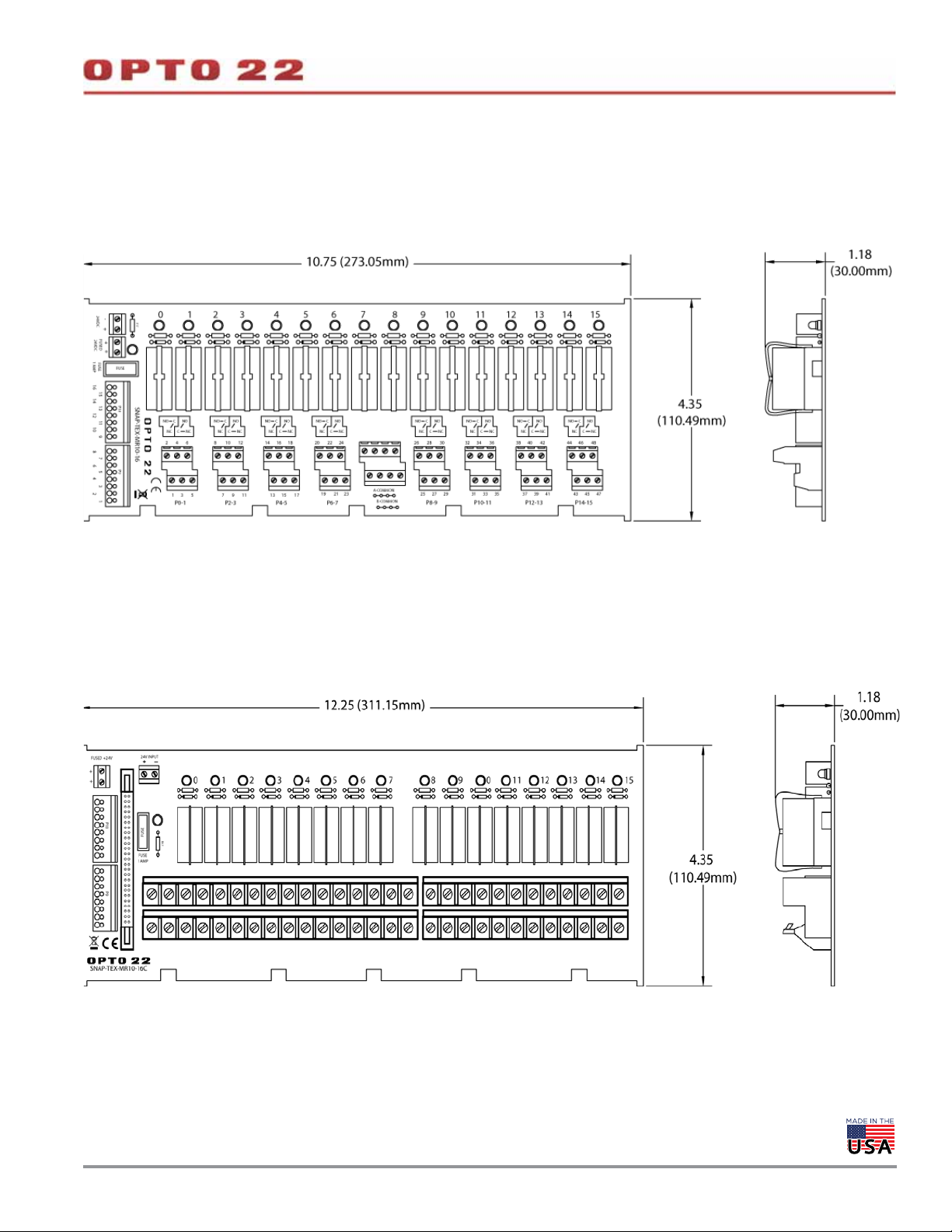
Dimensional Drawing—SNAP-TEX-MR10-16 Breakout Board
Dimensions are shown in inches (with centimeters in parentheses).
DA T A SHEET
Form 1756-200206
PAGE 15
Dimensional Drawing—SNAP-TEX-MR10-16C Breakout Board
Dimensions are shown in inches (with centimeters in parentheses).
OPTO 22 •
© 2008–2020 Opto 22. All rights reserved. Dimensions and specifications are subject to change. Brand or product names used herein are trademarks or registered trademarks of their respective companies or organizations.
Page 16
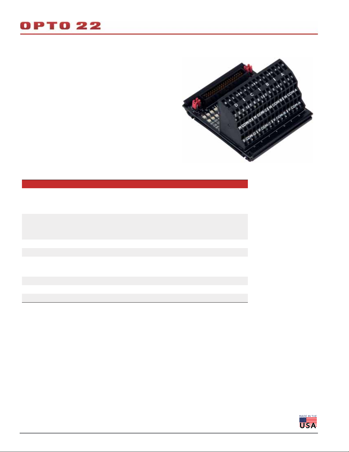
BREAKOUT BOARD FOR 32-POINT DIGITAL MODULES: SNAP-UDC-HDB
The small-footprint SNAP-UDC-HDB breakout board can be used with
either SNAP 32-point input modules or SNAP 32-point output modules.
This breakout board is ideal for tight locations. To save space, it does not
provide fuses. Spring-clamp wiring connectors make wiring the board
faster and simpler.
Connect the SNAP 32-point module to the board using a SNAP-HD-BF6
cable (see page 8).
Dimensional diagrams are on the next page. Wiring diagrams are on
page 38.
Specifications
SNAP-UDC-HDB Breakout Rack for High-Density Digital Input and Output Modules
SNAP-IDC-32, SNAP-IDC-32-FM
Used with
Connectors
Wire size Field connector: 12-28 AWG
Indicators 1 LED status indicator for each point (32 LEDs total)
Jumpers
Voltage 32 VDC maximum, 12–24 VDC nominal
Agency Approvals UL, CE, RoHS, DFARS
Warranty 30 months from date of manufacture
SNAP-IDC-32N, SNAP-IDC-32D, SNAP-IDC-32DN
SNAP-ODC-32-SNK, SNAP-ODC-32-SNK-FM
SNAP-ODC-32-SRC, SNAP-ODC-32-SRC-FM
40-pin header connects to 32-point module using SNAP-HD-BF6 cable.
64 spring-clamp terminal block provides 1 connection for each of 32 channels, 4 connections per 8-channel zone for field common, and 4 connections per 8-channel zone
for module common.
When using any SNAP-IDC-32 input module, install all four jumpers (JP1–JP4) in X
positions.
When using any SNAP-ODC-32 output module, install all four jumpers in Z positions.
DA T A SHEET
Form 1756-200206
PAGE 16
OPTO 22 •
© 2008–2020 Opto 22. All rights reserved. Dimensions and specifications are subject to change. Brand or product names used herein are trademarks or registered trademarks of their respective companies or organizations.
Page 17
BREAKOUT BOARDS FOR 32-POINT DIGITAL MODULES (CONTINUED)
Dimensional Drawing—SNAP-UDC-HDB
DA T A SHEET
Form 1756-200206
PAGE 17
OPTO 22 •
© 2008–2020 Opto 22. All rights reserved. Dimensions and specifications are subject to change. Brand or product names used herein are trademarks or registered trademarks of their respective companies or organizations.
Page 18

DA T A SHEET
Form 1756-200206
BREAKOUT BOARDS FOR 32-POINT DIGITAL MODULES: SNAP-IDC-HDB, SNAP-ODC-HDB
SNAP-IDC-HDB, SNAP-IDC-HDB-FM, SNAP-ODC-HDB, and
SNAP-ODC-HDB-FM breakout boards provide LED indicators and
easily accessible fused connectors for points on 32-point digital
input or output modules.
Wiring diagrams begin on page 43.
Specifications
SNAP-IDC-HDB and SNAP-IDC-HDB-FM Breakout Racks for High-Density Digital Input Modules
Used with SNAP-IDC-32, SNAP-IDC-32-FM, SNAP-IDC-32N, and SNAP-IDC-32DN
40-pin header connects to 32-point input module using SNAP-HD-BF6 header cable.
32 signal input connectors; each signal connector has a corresponding common connec-
Connectors
Indicators
Fusing
Jumpers
Voltage 32 VDC maximum, 12-24 VDC nominal
Agency Approvals
Warranty 30 months from date of manufacture
tor.
For each zone of 8 signal inputs, 1 connection for either module common or field common.
Wire size for field connectors: 16-20 AWG
1 LED for On/Off status of each signal input (32 signal LEDs total)
1 power status LED for each zone of 8 signal inputs (4 power LEDs total)
2 fuses (Module Common, Field Common) for each zone of 8 signal inputs (8 fuses total)
1 A fuses; replace with Pudenz 1 A automobile mini-fuse or equivalent.
For each zone of 8 signal inputs, 1 jumper controls whether module common or field common is used. Set jumpers to X position for digital input modules.
SNAP-IDC-HDB: UL, CE, RoHS, DFARS
SNAP-IDC-HDB-FM: FM, CE, RoHS, DFARS
PAGE 18
SNAP-ODC-HDB and SNAP-ODC-HDB-FM Breakout Racks for High-Density Digital Output Modules
Used with
Connectors
Indicators
Fusing
Jumpers
Voltage 32 VDC maximum, 12-24 VDC nominal
Agency Approvals
Warranty 30 months from date of manufacture
OPTO 22 •
© 2008–2020 Opto 22. All rights reserved. Dimensions and specifications are subject to change. Brand or product names used herein are trademarks or registered trademarks of their respective companies or organizations.
SNAP-ODC-32-SRC, SNAP-ODC-32-SRC-FM,
SNAP-ODC-32-SNK, and SNAP-ODC-32-SNK-FM
40-pin header; connects to 32-point sourcing or sinking module using
SNAP-HD-BF6 header cable.
32 signal output connectors; each signal connector has a corresponding common connector.
For each zone of 8 signal outputs, 1 connection for either module common or field common.
Wire size for field connectors: 16-20 AWG
1 LED for On/Off status of each signal output (32 signal LEDs total)
1 power status LED for each zone of 8 signal outputs (4 power LEDs total)
1 A fuses; 1 fuse for each signal output (32 signal fuses total)
Replace with Pudenz 1 A automobile mini-fuse or equivalent.
For each zone of 8 signal inputs, 1 jumper controls whether module common or field common is used. Set jumpers to Z position for digital output modules.
SNAP-ODC-HDB: UL, CE, RoHS, DFARS
SNAP-ODC-HDB-FM: FM, CE, RoHS, DFARS
Page 19

BREAKOUT BOARDS FOR 32-POINT DIGITAL MODULES (CONTINUED)
Dimensional Drawings
DA T A SHEET
Form 1756-200206
PAGE 19
X
Z
X
Z
X
Z
X
Z
SNAP-IDC-HDB and SNAP-IDC-HDB-FM breakout racks
Z
X
Z
X
X
Z
X
Z
SNAP-ODC-HDB and SNAP-ODC-HDB-FM breakout racks
OPTO 22 •
© 2008–2020 Opto 22. All rights reserved. Dimensions and specifications are subject to change. Brand or product names used herein are trademarks or registered trademarks of their respective companies or organizations.
Page 20

BREAKOUT BOARDS FOR 32-POINT DIGITAL MODULES: SNAP-UDC-HDB-G4
The SNAP-UDC-HDB-G4 breakout board connects a SNAP 32-point
digital module to G4 modules on the board, so you can switch or
monitor much larger loads than the SNAP module can handle by itself.
The SNAP-UDC-HDB-G4 holds 32 G4 modules (sold separately), one for
each point on the SNAP module.
A SNAP 32-point digital output module like the SNAP-ODC-32-SNK
can switch loads of 0.25 amps per point, but by going through G4
output modules on the board, it can switch loads of up to 3 amps per
point.
The module connects to the board using a SNAP-HD-BF6 cable (see
page 8). G4 modules on the board can be a mix of AC and DC, but they
must be all inputs or all outputs, depending on the SNAP module they
are connected to.
The board provides spring-clamp terminals for easier field wiring.
Dimensional diagrams are on page 21. Wiring diagrams begin on
page 41.
DA T A SHEET
Form 1756-200206
PAGE 20
Specifications
SNAP-UDC-HDB-G4 Breakout Rack for High-Density Digital Input or Output Module
Outputs: SNAP-ODC-32-SNK or SNAP-ODC-32-SNK-FM (all G4 modules must be
Used with
Connectors
Wire size Field connector: 12-28 AWG
Indicators 1 LED for logic power; 1 LED for G4 fuse test
Jumpers
Voltage 32 VDC maximum, 12–24 VDC nominal
Agency Approvals UL, CE, RoHS, DFARS
Warranty 30 months from date of manufacture
the same voltage)
Inputs: SNAP-IDC-32DN for 5 V G4 modules; SNAP-IDC-32N for 15 V or 24 V G4
modules
40-pin header connects to 32-point module using SNAP-HD-BF6 cable.
64 spring-clamp terminals provide 2 connections for each of 32 channels.
Additional 4 spring-clamp terminals are for logic power + and – (2 each).
When using a SNAP-ODC-32-SNK output module, install JP1 in the negative (–)
position.
When using a SNAP-IDC-32 input module, install JP1 in the positive (+) position.
OPTO 22 •
© 2008–2020 Opto 22. All rights reserved. Dimensions and specifications are subject to change. Brand or product names used herein are trademarks or registered trademarks of their respective companies or organizations.
Page 21

BREAKOUT BOARDS FOR 32-POINT DIGITAL MODULES (CONTINUED)
Dimensional Drawing—SNAP-UDC-HDB-G4
DA T A SHEET
Form 1756-200206
PAGE 21
SNAP-UDC-HDB-G4 shown with G4 modules
(sold separately)
OPTO 22 •
© 2008–2020 Opto 22. All rights reserved. Dimensions and specifications are subject to change. Brand or product names used herein are trademarks or registered trademarks of their respective companies or organizations.
Page 22

DA T A SHEET
Form 1756-200206
PAGE 22
BREAKOUT BOARDS FOR 32-POINT ANALOG MODULES: SNAP-AIMA-HDB AND SNAP-AIV-HDB
Changing Negative to Positive Values
(SNAP-AIMA-HDB board only) To read positive values, when you
configure points on the module, choose the scalable option and
enter the corresponding positive values, like this:
SNAP-AIMA-HDB breakout board
SNAP-AIMA-HDB, SNAP-AIMA-HDB-FM, SNAP-AIV-HDB, and
SNAP-AIV-HDB-FM breakout boards are primarily designed for use
with SNAP-AIMA-32, SNAP-AIMA-32-FM, SNAP-AIV-32, and
SNAP-AIV-32-FM analog input modules, respectively. Each of these
modules provides 32 input points. The breakout boards provide easy
accessibility for wiring points to field devices. Use the SNAP-HD-BF6
cable for wiring connections between the module and the breakout
board.
Note for the SNAP-AIMA-32 or SNAP-AIMA-32-FM: if you are using one
of these modules with loop powered (2-wire) devices, connect to the
SNAP-AIMA-HDB or SNAP-AIMA-HDB-FM rack as shown on page 51.
However, if you are using the SNAP-AIMA-32 (or -FM) with
self-powered devices (4-wire), do not use the SNAP-AIMA-HDB (or
-FM) boards, which have a current limiter. Instead, wire to the
SNAP-AIV-HDB or SNAP-AIV-HDB-FM as shown on page 52 (negative
common) or page 53 (positive common).
This may seem odd, but it works. Don’t be confused by the “Lower”
and “Upper” labels for the values. Positive values sent to the module
will be shown as the correct positive values within your PAC Control
strategy.
Scaling Values
Similarly, if you need to scale values for your application, enter the
positive values you need. If you want the field signal of 4 to 20 mA to
be scaled as 0 to 100%, then configure as shown below:
CAUTION: We strongly recommend that you use a breakout board with
the SNAP-AIMA-32 (or -FM) module. Without the board, miswiring of any
point on the module can cause severe out-of-warranty damage. The
breakout board protects the module from many wiring errors.
Working with Module Values
AIMA modules used with a SNAP-AIV-HDB board read normally.
However, values on AIMA modules used with a SNAP-AIMA-HDB
board are read as negative values. For example, a value of 10 mA on
the module will be read as -10 mA. (Note: If no readings appear, try
reversing field connections on the board.)
Because these readings are negative values, they can be confusing to
work with. This section shows you how to easily change them to
positive values or scale them to the positive readings you need. This
section applies only to the SNAP-AIMA-HDB board.
OPTO 22 •
© 2008–2020 Opto 22. All rights reserved. Dimensions and specifications are subject to change. Brand or product names used herein are trademarks or registered trademarks of their respective companies or organizations.
Page 23

BREAKOUT BOARDS FOR 32-POINT ANALOG MODULES (CONTINUED)
Dimensional Drawing—SNAP-AIMA-HDB and SNAP-AIMA-HDB-FM Breakout Boards
DA T A SHEET
Form 1756-200206
PAGE 23
Dimensional Drawing—SNAP-AIV-HDB and SNAP-AIV-HDB-FM Breakout Boards
OPTO 22 •
© 2008–2020 Opto 22. All rights reserved. Dimensions and specifications are subject to change. Brand or product names used herein are trademarks or registered trademarks of their respective companies or organizations.
Page 24

WIRING DIAGRAMS FOR CABLES AND BREAKOUT BOARDS
Module Type To Breakout Board See page
SNAP-TEX-32 25
SNAP-TEX-FB16-H
4-point digital modules
1-, 2-, or 4-point analog modules SNAP-TEX-32 25
8-point analog output module SNAP-TEX-32 32
16-point digital modules
32-point digital modules
32-point digital inputs or outputs SNAP-UDC-HDB 38
32-point digital inputs or outputs to G4 I/O SNAP-UDC-HDB-G4 41
32-point digital inputs SNAP-IDC-HDB 43
32-point digital outputs SNAP-ODC-HDB 46
32-point digital outputs (sourcing only)
32-point SNAP-AIMA-32 SNAP-AIMA-HDB 51
32-point SNAP-AIV-32 SNAP-AIV-HDB 52
32-point SNAP-AIV-32 SNAP-TEX-32 36
SNAP-TEX-FB16-L
SNAP-TEX-MR10-4
SNAP-TEX-MR10-16
SNAP-TEX-MR10-16C 30
SNAP-TEX-32 33
SNAP-TEX-FB16-H
SNAP-TEX-FB16-L
SNAP-TEX-MR10-16C 31
No breakout board 35
SNAP-TEX-32 36
SNAP-TEX-FB16-H
SNAP-TEX-FB16-L
SNAP-TEX-MR10-16 49
SNAP-TEX-MR10-16C 50
26
29
34
37
DA T A SHEET
Form 1756-200206
PAGE 24
OPTO 22 •
© 2008–2020 Opto 22. All rights reserved. Dimensions and specifications are subject to change. Brand or product names used herein are trademarks or registered trademarks of their respective companies or organizations.
Page 25

Form 1756-200206
WIRING: 4-POINT DIGITAL OR ANALOG MODULE TO SNAP-TEX-32 BREAKOUT BOARD
Wire up to eight 4-point modules to the SNAP-TEX-32.
Only one module is shown below.
DA T A SHEET
PAGE 25
Cable:
SNAP-TEX-CBO6
SNAP-TEX-CBE6
SNAP-TEX-CBS6
Find the appropriate cable for
your module in the tables
starting on page 2.
1 Black
2 Red
3 Blue
4 Orange
5 Y ellow
6 Brown
7 Red/blk
8 Blue/blk
SNAP-TEX-32
breakout board
For field wiring, see the
data sheet for the module
you are using.
OPTO 22 •
© 2008–2020 Opto 22. All rights reserved. Dimensions and specifications are subject to change. Brand or product names used herein are trademarks or registered trademarks of their respective companies or organizations.
Page 26

DA T A SHEET
Form 1756-200206
WIRING: 4-POINT DIGITAL MODULE TO SNAP-TEX-FB16-H OR SNAP-TEX-FB16-L BOARD
General Instructions
PAGE 26
SNAP-TEX-FB16-H or SNAP-TEX-FB16-L
breakout board
Load 1
2
1
357
Connect channel 0 load to field terminals 1
and 2. Connect channel 1 load to terminals
3 and 4. And so on.
8
For DC output modules:
See “” on page 27
FUSE
COMMON
MODULE
COMMON
For AC output modules:
Connect the hot wire to one of
the Fuse Common terminals.
Connect the neutral wire to one
of the Module Common
terminals.
NOTE: Extra terminals are provided
to daisy-chain power to multiple
breakout boards.
SNAP-ODC5
OPTO 22 •
SNAP-TEX-FB16-H or SNAP-TEX-FB16-L
breakout board
Fuse Common
Module Common
Load
Load
Example for the SNAP-ODCSNK
and SNAP-ODC5ASNK modules.
The polarity depends on which
SNAP ODC module is used.
See page 27.
© 2008–2020 Opto 22. All rights reserved. Dimensions and specifications are subject to change. Brand or product names used herein are trademarks or registered trademarks of their respective companies or organizations.
Page 27

Form 1756-200206
4-POINT DIGITAL MODULE TO SNAP-TEX-FB16-H OR SNAP-TEX-FB16-L (CONTINUED)
Polarity and Module T ype
When using DC output modules, the polarity for connecting the DC
power source to the Module Common and Fuse Common terminals
on the breakout board depends on the SNAP digital output module
being used.
The SNAP-TEX-FB16-H and SNAP-TEX-FB16-L breakout boards use the
Module Common to connect to all the odd terminals of the SNAP
output module.
Fuse Common goes to the individual fuses, which go to the odd
terminals on this breakout board.
The even terminals on the SNAP output modules go to the even
terminals via the SNAP-TEX cable.
SNAP-ODC5SNK, SNAP-ODC5ASNK
These modules internally tie all odd terminals together.
• Connect the positive side of the DC power source to Fuse
Common.
• Connect the negative side of the DC power source to Module
Common.
DA T A SHEET
PAGE 27
SNAP-ODC5SRC
This module internally ties all even terminals together.
• Connect the positive side of the DC power source to Module
Common.
• Connect the negative side of the DC power source to Fuse
Common.
SNAP-ODC5MA, SNAP-ODC5-i, SNAP-ODC5A-i
IMPORTANT: The points on these modules are isolated from each other.
However, when used with this breakout board, the
channel-to-channel isolation is bypassed, because this breakout board
ties the module’s odd terminals together.
• Connect the positive side of the DC power source to Module
Common.
• Connect the negative side of the DC power source to Fuse
Common.
OPTO 22 •
© 2008–2020 Opto 22. All rights reserved. Dimensions and specifications are subject to change. Brand or product names used herein are trademarks or registered trademarks of their respective companies or organizations.
Page 28

Form 1756-200206
4-POINT DIGITAL MODULE TO SNAP-TEX-FB16-H OR SNAP-TEX-FB16-L (CONTINUED)
Resistor Fuse Blown-fuse LED
CAUTION: Do NOT use the SNAP-TEX-CBE6
(even pins commoned) cable with this board.
The board has odd pins commoned.
Resistor LED Fuse
Cable:
SNAP-TEX-CBO6
SNAP-TEX-CBS6
Find the appropriate cable for your
module in the tables starting on
page 2.
Also see “General Instructions” on
page 26.
DA T A SHEET
PAGE 28
OPTO 22 •
© 2008–2020 Opto 22. All rights reserved. Dimensions and specifications are subject to change. Brand or product names used herein are trademarks or registered trademarks of their respective companies or organizations.
Page 29

DA T A SHEET
Form 1756-200206
WIRING: 4-POINT DIGITAL MODULE TO SNAP-TEX-MR10-4 OR SNAP-TEX-MR10-16 BOARD
The example shows wiring for the first two points on a
SNAP-ODC5-i module to a SNAP-TEX-MR10-4 board.
Wiring connections shown are for a SNAP-TEX-CBO6 cable.
Wiring 4-point modules to a SNAP-TEX-MR10-16 board is similar.
The MR10-16 has 16 channels rather than four.
Cable: SNAP-TEX-CBO6
Module: SNAP-ODC5-i
For other module/cable options
with this board, see
page 2.
Field wiring
For normally open (N.O.) or normally closed (N.C.)
PAGE 29
NOTE: Transient protection must be used on inductive loads.
OPTO 22 •
© 2008–2020 Opto 22. All rights reserved. Dimensions and specifications are subject to change. Brand or product names used herein are trademarks or registered trademarks of their respective companies or organizations.
Page 30

WIRING: 4-POINT DIGITAL OUTPUT MODULE TO SNAP-TEX-MR10-16C BOARD
Two 4-point ODC modules can be wired to each of the two spring connectors.
The example shows the first two points on a SNAP-ODC5-i module.
Wiring connections shown are for a SNAP-TEX-CBO6 cable.
Spring connectors for
standard, 4-point
ODC modules
Cable: SNAP-TEX-CBO6
For other module/cable options with
Module: SNAP-ODC5-i
this board, see
page 2.
Field connectors
DA T A SHEET
Form 1756-200206
PAGE 30
Mechanical relays
Pins 4-7 to the next
ODC module
FUSED +24V
+
+
Wiring connections shown
are for SNAP-TEX-CBO6.
One of two spring connectors
NOTE: If you are using a SNAP-TEX-CBS6 cable instead of the
SNAP-TEX-CBO6, jumpers are required for a SNAP-ODC5-I module.
They are not required for a SNAP-ODC5SRC module.
Power
Supply
24 VDC
+
–
24V INPUT
Also see next page.
NOTE: Transient protection must be used
on inductive loads.
OPTO 22 •
© 2008–2020 Opto 22. All rights reserved. Dimensions and specifications are subject to change. Brand or product names used herein are trademarks or registered trademarks of their respective companies or organizations.
Page 31
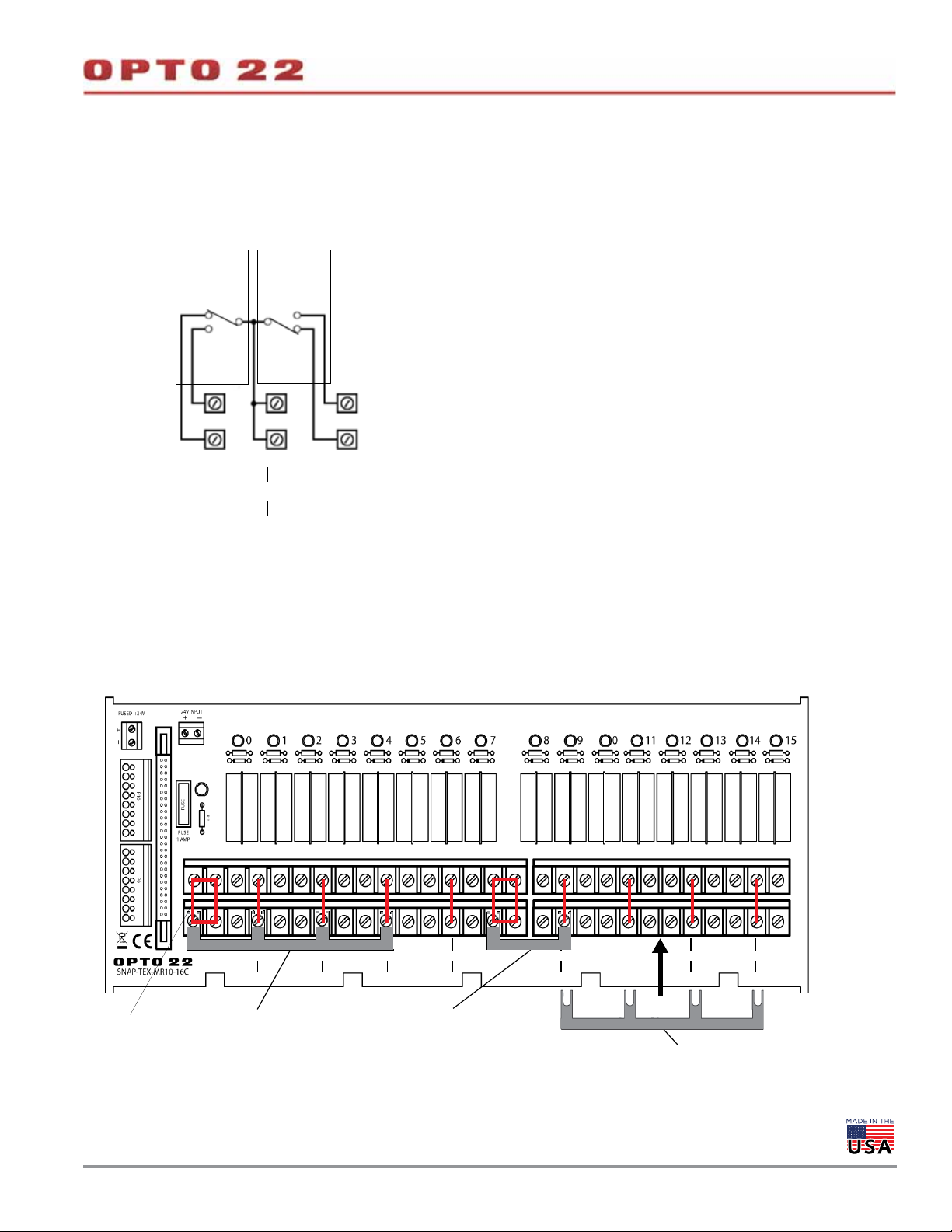
4-PT OR 16-PT DIGIT AL OUTPUT MODULE TO SNAP-TEX-MR10- 16C
SNAP-TEX-MR10-16C Relay Group
The diagram below shows relays 0 and 1 in a relay group.
NOTE: The diagrams on this page apply to the
SNAP-TEX-MR10-16C breakout board used with
either a 4-point digital output module or a
16-point digital output module.
NOTE: Transient protection must be used on inductive loads.
DA T A SHEET
Form 1756-200206
PAGE 31
NO NO
NC NC
C
NO NO
0C1
NC NC
Terminals 0 and 1
Jumper Straps—SNAP-TEX-MR10-16C Breakout Board
This diagram shows an example using jumper straps, Opto 22 part numbers STRAP2Q and STRAP4Q.
GROUP A
COMMON
NO NO NO NO NO NO NO NO
01234 567
CCCC
NC NC NC NC NC NC NC NC
STRAP4Q
STRAP2Q
GROUP B
COMMON
NO NO NO NO NO NO NO NO
CCCC
8 9 10 11 12 13 14 15
NC NC NC NC NC NC NC NC
Traces on board
STRAP4Q
OPTO 22 •
© 2008–2020 Opto 22. All rights reserved. Dimensions and specifications are subject to change. Brand or product names used herein are trademarks or registered trademarks of their respective companies or organizations.
Page 32

WIRING: 8-POINT ANALOG OUTPUT MODULE TO SNAP-TEX-32 BREAKOUT BOARD
Use up to four 8-point SNAP-AOVA-8 analog output modules per board.
Use cable SNAP-HD-20F6. Wiring example for one module is shown below.
Black: 24 VDC Excitation (Negative)
White with Black: 24 VDC Excitation (Positive)
Cable:
SNAP-HD-20F6
Purple with Yellow (Not used)
Yellow with Purple (Not used)
1 Blue
2 White with Blue
3 Pink
4 White with Pink
5 Gray
6 White with Gray
7 Green
8 White with Green
9 Orange
10 White with Orange
11 Red
12 White with Red
13 Purple
14 White with Purple
15 Y ellow
16 White with Yellow
SNAP-TEX-32
breakout board
DA T A SHEET
Form 1756-200206
PAGE 32
OPTO 22 •
© 2008–2020 Opto 22. All rights reserved. Dimensions and specifications are subject to change. Brand or product names used herein are trademarks or registered trademarks of their respective companies or organizations.
Page 33

WIRING: 16-POINT DIGITAL MODULE TO SNAP-TEX-32 BREAKOUT BOARD
DA T A SHEET
Form 1756-200206
PAGE 33
Use two modules per board. The SNAP-HD-ACF6 cable assembly
includes two identical cables, each with a 16-pin connector. It takes
both cables to cover one module.
16-point module (top view)
Cable:
Wiring for one cable is shown in the diagram below. Field connection
wires are twisted pair.
SNAP-TEX-32 breakout board
Red
White
Black
Orange
Black
Brown
Black
Yellow
Black
Blue
Black
Green
Black
White
Black
Red
NOTE: Field wires for the cable are in twisted pairs, so you
can see which wires go to each point.
Even though some wire colors repeat, there is no internal
connection between points. This module’s 16 points are
isolated from each other.
OPTO 22 •
© 2008–2020 Opto 22. All rights reserved. Dimensions and specifications are subject to change. Brand or product names used herein are trademarks or registered trademarks of their respective companies or organizations.
Page 34

DA T A SHEET
Form 1756-200206
WIRING: 16-POINT DIGITAL INPUT MODULE TO SNAP-TEX-FB16-H OR SNAP-TEX-FB16-L
PAGE 34
Note: When using a breakout board, each connector will
have six unused wires (5 Black and 1 Red).
Cable: SNAP-HD-ACF6
ACOM Black
A0 Red
A1 White
A2 Green
A3 Blue
ACOM Black
A4 Y ellow
A5 Brown
A6 Orange
Resistor Fuse Blown-fuse LED
Resistor LED Fuse
A7 White
BCOM Black
B0 Red
B1 White
B2 Green
B3 Blue
BCOM Black
B4 Y ellow
B5 Brown
B6 Orange
B7 White
Fuse Common
Module Common
OPTO 22 •
© 2008–2020 Opto 22. All rights reserved. Dimensions and specifications are subject to change. Brand or product names used herein are trademarks or registered trademarks of their respective companies or organizations.
Page 35

Form 1756-200206
WIRING: 16-POINT DIGITAL INPUT MODULE TO FIELD DEVICES (NO BREAKOUT BOARD)
The following diagrams show wiring from the SNAP-HD-ACF6 cable
to a 16-channel module (left) and pinouts to field devices (right).
The small six-pin connector on the top of the module connects to the
optional OptoTerminal-G20 using a special adapter cable, included
with the OptoTerminal.
Cable: SNAP-HD-ACF6
Port for OptoTerminal-G20
DA T A SHEET
PAGE 35
From SNAP-HD-ACF6 cable
First connector with 8 twisted pairs
To field devices
Second connector with 8 twisted pairs
NOTE: The connectors on these modules are not polarity-specific. You can connect the positive lead (+) for each channel (or point)
to either L1 or L2, and this can vary from point to point on the module.
OPTO 22 •
© 2008–2020 Opto 22. All rights reserved. Dimensions and specifications are subject to change. Brand or product names used herein are trademarks or registered trademarks of their respective companies or organizations.
Page 36

WIRING: 32-POINT DIGITAL MODULE TO SNAP-TEX-32 BREAKOUT BOARD
SNAP-HD-CBF6 Cable Wiring
The following table shows connector wiring for the SNAP-HD-CBF6.
Wires from the cable are grouped into four sets.
Set A Set B Set C Set D
Wires Point Wires Point Wires Point Wires Point
A0 Gray 0 B0 Gray 8 C0 Gray 16 D0 Gray 24
A1 Blue 1 B1 Blue 9 C1 Blue 17 D1 Blue 25
A2 Yellow 2 B2 Yellow 10 C2 Yellow 18 D2 Yellow 26
A3 Red 3 B3 Red 11 C3 Red 19 D3 Red 27
A4 White 4 B4 White 12 C4 White 20 D4 White 28
A5 Violet 5 B5 Violet 13 C5 Violet 21 D5 Violet 29
A6 Green 6 B6 Green 14 C6 Green 22 D6 Green 30
A7 Orange 7 B7 Orange 15 C7 Orange 23 D7 Orange 31
ACOM Blk/Brn com BCOM Blk/Brn com CCOM Blk/Brn com DCOM Blk/Brn com
DA T A SHEET
Form 1756-200206
PAGE 36
The four sets relate to point numbers on the module as shown below.
Harness
Wire Color
Gray 40 A0
Blue 38 A1
Yellow 36 A2
Red 34 A3
Black 32 ACOM
Gray 30 B0
Blue 28 B1
Yellow 26 B2
Red 24 B3
Black 22 BCOM
Gray 20 C0
Blue 18 C1
Yellow 16 C2
Red 14 C3
Black 12 CCOM
Pin
Number
Signal
Signal
A4 39 White
A5 37 Violet
A6 35 Green
A7 33 Orange
ACOM 31 Brown
B4 29 White
B5 27 Violet
B6 25 Green
B7 23 Orange
BCOM 21 Brown
C4 19 White
C5 17 Violet
C6 15 Green
C7 13 Orange
CCOM 11 Brown
Pin
Number
Harness
Wire Color
Connector wiring for SNAP-ODC-32-SNK, SNAP-ODC-32-SRC, SNAP-IDC-32,
-FM versions, SNAP-IDC-32N, and SNAP-IDC-32DN (top view of module)
OPTO 22 •
© 2008–2020 Opto 22. All rights reserved. Dimensions and specifications are subject to change. Brand or product names used herein are trademarks or registered trademarks of their respective companies or organizations.
Page 37

DA T A SHEET
Form 1756-200206
PAGE 37
WIRING: 32-POINT DIGITAL OUTPUT MODULE TO SNAP-TEX-FB16-H OR SNAP-TEX-FB16-L
From SNAP-ODC-32-SRC or SNAP-ODC-32-SNK
digital output module. Use two boards per module.
See tables on page 36.
Cable: SNAP-HD-CBF6
ACOM Black
A0 Gray
A1 Blue
A2 Y ellow
A3 Red
ACOM Brown
A4 White
A5 Violet
A6 Green
Resistor Fuse Blown-fuse LED
Resistor LED Fuse
A7 Orange
BCOM Black
B0 Gray
B1 Blue
B2 Y ellow
B3 Red
BCOM Brown
B4 White
B5 Violet
B6 Green
B7 Orange
Fuse Common
Module Common
For SRC module, module
common is positive, and
field commons (1, 3, 5,
and 7) are negative.
For SNK module, module
common is negative, and
field commons (1, 3, 5,
and 7) are positive.
OPTO 22 •
© 2008–2020 Opto 22. All rights reserved. Dimensions and specifications are subject to change. Brand or product names used herein are trademarks or registered trademarks of their respective companies or organizations.
Page 38

Form 1756-200206
WIRING: 32-POINT DIGITAL INPUT OR OUTPUT MODULE TO SNAP-UDC-HDB BOARD
SNAP-HD-BF6 cable
Run a SNAP-HD-BF6 cable from the top of the SNAP 32-point module to
the 40-pin connector on the breakout board.
Note that points on the cable are in four groups of eight points: A0–A7,
B0–B7, C0–C7, and D0–D7. These correspond to the groups of
spring-clamp connectors on the breakout board, as shown below.
For all spring clamp connectors: Insert a small standard screwdriver into the
top of the small hole and push the handle away from you so that the larger hole
below opens. Insert the wire into the larger hole and remove the screwdriver.
DA T A SHEET
PAGE 38
40-pin connector
Jumpers:
• For input modules, set all four
jumpers (JP1–JP4) to the X position.
• For output modules, set all four
jumpers to the Z position.
Field wiring for group A:
Points A0–A7
Module common (group A)
Field common (group A)
OPTO 22 •
© 2008–2020 Opto 22. All rights reserved. Dimensions and specifications are subject to change. Brand or product names used herein are trademarks or registered trademarks of their respective companies or organizations.
Page 39

WIRING: 32-POINT DIGITAL INPUT MODULES TO SNAP-UDC-HDB BOARD
SNAP-IDC-32, SNAP-IDC-32FM, and SNAP-IDC-32D
Jumpers: For input modules, set all
four jumpers to the X position.
DA T A SHEET
Form 1756-200206
PAGE 39
SNAP-IDC-32N and SNAP-IDC-32DN
Jumpers: For input modules, set all
four jumpers to the X position.
OPTO 22 •
© 2008–2020 Opto 22. All rights reserved. Dimensions and specifications are subject to change. Brand or product names used herein are trademarks or registered trademarks of their respective companies or organizations.
Page 40

WIRING: 32-POINT DIGITAL OUTPUT MODULES TO SNAP-UDC-HDB BOARD
SNAP-ODC-32 - SNK and SNAP -ODC -32-SNK-FM
Jumpers: For output modules, set all four
jumpers to the Z position.
All groups must be fused. Either fuse
each point or fuse each group of points
(for example, Group A or Group B).
DA T A SHEET
Form 1756-200206
PAGE 40
SNAP-ODC-32-SRC and SNAP-ODC-32-SRC-FM
Jumpers: For output modules, set all four
jumpers to the Z position.
All groups must be fused. Either fuse
each point or fuse each group of points
(for example, Group A or Group B).
OPTO 22 •
© 2008–2020 Opto 22. All rights reserved. Dimensions and specifications are subject to change. Brand or product names used herein are trademarks or registered trademarks of their respective companies or organizations.
Page 41

DA T A SHEET
Form 1756-200206
WIRING: 32-POINT DIGITAL INPUT OR OUTPUT MODULE TO SNAP-UDC-HDB-G4 BOARD
Because the SNAP-UDC-HDB-G4 can accommodate a variety of G4 digital input and output modules, wiring
depends on the modules you are using. G4 modules on the board can be a mix of AC and DC, but they must be
all inputs or all outputs and must have the same logic voltage (all 5 V, or all 15 V, or all 24 V).
Use the SNAP 32-point module and jumper setting to match your G4 modules:
G4 module type Voltage Use this SNAP module... Set JP1 to...
Outputs (must all be same logic voltage) 5 V, 15 V, or 24 V
Inputs (must all be same logic voltage)
5 V SNAP-IDC-32DN LOGIC +
15 V or 24 V SNAP-IDC-32N LOGIC +
Use a SNAP-HD-BF6 cable to connect the SNAP module to the board.
SNAP-ODC-32-SNK
SNAP-ODC-32-SNK-FM
LOGIC –
PAGE 41
For all spring clamp connectors: Insert a small standard
screwdriver into the top of the small hole and push the handle away
from you so that the larger hole below opens. Insert the wire into the
larger hole and remove the screwdriver. See next page for diagram.
All G4 modules you mount on the rack must be of the
same voltage: 5 V, 15 V, or 24 V.
Apply logic voltage to the rack according to the modules
on it. For example, if you are using 5 V G4 modules, apply
5 VDC to the rack.
Wire incoming logic voltage to one plus and one minus
(it doesn’t matter which one). The second pair is available
if you want to daisy chain racks.
Run a SNAP-HD-BF6 cable from the top of the SNAP
module to the 40-pin connector on the board.
SNAP-HD-BF6 cable
For each G4 module, wire field devices to the corresponding A and B connectors.
For example, wire the module in the A0 position to the connectors marked
A0 A and B. See field wiring diagrams on the next page.
Remember to set jumper 1 (JP1) to match the G4 modules you use:
- For output modules, set JP1 to LOGIC –.
- For input modules, set JP1 to LOGIC +.
OPTO 22 •
© 2008–2020 Opto 22. All rights reserved. Dimensions and specifications are subject to change. Brand or product names used herein are trademarks or registered trademarks of their respective companies or organizations.
Page 42

DA T A SHEET
Form 1756-200206
PAGE 42
WIRING: 32-POINT DIGITAL INPUT OR OUTPUT MODULE TO SNAP-UDC-HDB-G4 (CONTINUED)
Field wiring for G4 modules on the SNAP-UDC-HDB-G4
Input modules using DC field voltages
G4IDC5
G4IDC5B
G4IDC5D
G4IDC5G
G4IDC5K
G4IDC5MA
G4IAC5
G4IAC5A
G4IAC5M
These AC input modules work with either AC or DC field voltages.
For DC voltages, use the diagram at right. For AC field voltages,
use the diagram below.
Input modules using AC field voltages
G4IAC5
G4IAC5A
G4IAC5MA
G4IDC5
G4IDC5G
G4IDC5MA
These DC input modules work with either DC or AC field voltages.
For AC voltages, use the diagram at right. For DC field voltages,
use the diagram above.
Output modules using DC field voltages
G4ODC5
G4ODC5A
G4ODC5MA
D7
A0
D7
A0
D7
A0
A0 A
A0 B
D7 A
D7 B
A0 A
A0 B
D7 A
D7 B
A0 A
A0 B
D7 A
D7 B
Output modules using AC field voltages
G4OAC5
G4OAC5A
G4OAC5A5
G4OAC5MA
G4OAC5AMA
A0
D7
A0 A
A0 B
D7 A
D7 B
For all spring clamp connectors: Insert a small standard screwdriver into the top of
the small hole and push the handle away from you so that the larger hole below opens.
Insert the wire into the larger hole and remove the screwdriver.
OPTO 22 •
© 2008–2020 Opto 22. All rights reserved. Dimensions and specifications are subject to change. Brand or product names used herein are trademarks or registered trademarks of their respective companies or organizations.
Page 43

WIRING: 32-POINT DIGITAL INPUT MODULE TO SNAP-IDC-HDB BOARD
DA T A SHEET
Form 1756-200206
PAGE 43
JP-D JP-C
X
Z
JP-B JP-A
Set jumpers to the X position for
X
Z
X
Z
SNAP-IDC-32 (or -FM) or SNAP-IDC-32D
X
all input modules.
Z
There is one power status
LED for each zone of 8
signal inputs (4 power
LEDs total).
There is one LED for each
signal input (32 signal
LEDs total)
–
Module
COM
+
–
Module
COM
+
Field
COM
SNAP-IDC-32N or SNAP-IDC-32DN
–
Field
COM
Connect the negative lead (–)
from the power supply to one
Module COM terminal. Connect
the positive lead (+) to one
Field COM terminal.
Connect the positive lead (+)
from the power supply to one
Module COM terminal. Connect
the negative lead (–) to one
Field COM terminal.
+
Signal shown is for SNAP-IDC-32 and -FM and
SNAP-IDC-32D.
Signal reverses for SNAP-IDC-32N and -32DN.
OPTO 22 •
© 2008–2020 Opto 22. All rights reserved. Dimensions and specifications are subject to change. Brand or product names used herein are trademarks or registered trademarks of their respective companies or organizations.
Page 44

32-POINT DIGITAL INPUT MODULE TO SNAP-IDC-HDB (CONTINUED)
Modules—this diagram applies to:
SNAP-IDC-32
SNAP-IDC-32-FM
SNAP-IDC-32N
IMPORTANT: All SNAP-IDC-32 modules are
polarity specific and must be wired as shown.
DA T A SHEET
Form 1756-200206
PAGE 44
OPTO 22 •
© 2008–2020 Opto 22. All rights reserved. Dimensions and specifications are subject to change. Brand or product names used herein are trademarks or registered trademarks of their respective companies or organizations.
Page 45

32-POINT DIGITAL INPUT MODULE TO SNAP-IDC-HDB (CONTINUED )
Modules—this diagram applies to:
SNAP-IDC-32-D
SNAP-IDC-32-DN
IMPORTANT: All SNAP-IDC-32 modules are
polarity specific and must be wired as shown.
DA T A SHEET
Form 1756-200206
PAGE 45
OPTO 22 •
© 2008–2020 Opto 22. All rights reserved. Dimensions and specifications are subject to change. Brand or product names used herein are trademarks or registered trademarks of their respective companies or organizations.
Page 46

WIRING: 32-POINT DIGITAL OUTPUT MODULE TO SNAP-ODC-HDB BOARD
JP-D JP-C JP-B JP-A
DA T A SHEET
Form 1756-200206
PAGE 46
X
Z
X
Z
Power Supply Connections
Set jumpers to the Z position.
X
Z
SNAP-ODC-32-SRC (or -FM)
X
Z
+
Module
COM
Module
COM
OPTO 22 •
© 2008–2020 Opto 22. All rights reserved. Dimensions and specifications are subject to change. Brand or product names used herein are trademarks or registered trademarks of their respective companies or organizations.
–
Connect the positive lead (+)
from the power supply to one
Module COM terminal. Connect
the negative lead (–) to one
Field COM terminal.
Field
COM
SNAP-ODC-32-SNK (or -FM)
–
+
Connect the negative lead (–)
from the power supply to one
Module COM terminal. Connect
the positive lead (+) to one
Field COM terminal.
Field
COM
Page 47

32-POINT DIGITAL OUTPUT MODULE TO SNAP-ODC-HDB (CONTINUED)
Field Connections
Nominal 12–24 VDC
Typical for sinking Typical for sourcing
DA T A SHEET
Form 1756-200206
PAGE 47
OPTO 22 •
© 2008–2020 Opto 22. All rights reserved. Dimensions and specifications are subject to change. Brand or product names used herein are trademarks or registered trademarks of their respective companies or organizations.
Page 48

32-POINT DIGITAL OUTPUT MODULE TO SNAP-ODC-HDB (CONTINUED)
B0
B4
B1
B5
B2
B6
B3
B7
BCOM
12–24 VDC Nominal
C0
C4
C1
C5
C2
C6
C3
C7
CCOM
12–24 VDC Nominal
D0
D4
D1
D5
D2
D6
D3
D7
DCOM
12–24 VDC Nominal
+
12–24 VDC Nominal
+
+
+
B0
B4
B1
B5
B2
B6
B3
B7
BCOM
12–24 VDC Nominal
C0
C4
C1
C5
C2
C6
C3
C7
CCOM
12–24 VDC Nominal
D0
D4
D1
D5
D2
D6
D3
D7
DCOM
12–24 VDC Nominal
A0
A4
A1
A5
A2
A6
A3
A7
ACOM
+
12–24 VDC Nominal
LO
LO
LO
LO
LO
LO
LO
LO
LO
LO
LO
LO
LO
LO
LO
LO
LO
LO
LO
LO
LO
LO
LO
LO
LO
LO
LO
LO
LO
LO
LO
LO
SNAP-ODC-32-SRC
Load Sourcing Module
(Top view of module)
SNAP-ODC-32-SNK
Load Sinking Module
(Top view of module)
+
+
+
LO
LO
LO
LO
LO
LO
LO
LO
LO
LO
LO
LO
LO
LO
LO
LO
LO
LO
LO
LO
LO
LO
LO
LO
LO
LO
LO
LO
LO
LO
LO
LO
LO
LO
LO
LO
LO
LO
LO
LO
LO
LO
LO
LO
LO
LO
LO
LO
LO
LO
LO
LO
LO
LO
LO
LO
LO
LO
LO
LO
LO
LO
LO
LO
LO
LO
LO
LO
LO
LO
LO
LO
LO
LO
LO
LO
LO
LO
LO
LO
LO
LO
LO
LO
LO
LO
LO
LO
LO
LO
LO
LO
LO
LO
LO
LO
LO
LO
LO
LO
LO
LO
LO
LO
LO
LO
LO
LO
LO
LO
LO
LO
LO
LO
LO
LO
LO
LO
LO
LO
LO
LO
LO
LO
LO
LO
LO
LO
LO
LO
LO
LO
LO
LO
LO
LO
LO
LO
LO
LO
LO
LO
LO
LO
LO
LO
LO
LO
LO
LO
LO
LO
LO
LO
LO
LO
LO
LO
LO
LO
LO
LO
LO
LO
LO
LO
LO
LO
LO
LO
LO
LO
LO
LO
LO
LO
LO
LO
LO
LO
LO
LO
LO
LO
FUSING
For both sourcing and sinking
modules, either fuse each point
(as shown in the first and third
groups, below) or fuse each
group of points (as shown in
the second and fourth groups).
A0
A4
A1
A5
A2
A6
A3
A7
ACOM
All groups must be fused.
DA T A SHEET
Form 1756-200206
PAGE 48
OPTO 22 •
© 2008–2020 Opto 22. All rights reserved. Dimensions and specifications are subject to change. Brand or product names used herein are trademarks or registered trademarks of their respective companies or organizations.
Page 49

WIRING: 32-POINT DIGITAL OUTPUT MODULE TO SNAP-TEX-MR10-16 BOARD
For 32-point sourcing modules only (SNAP-ODC-32-SRC or SNAP-ODC-32-SRC-FM).
Use two breakout boards with one module and one SNAP-HD-CBF6 cable.
SNAP-TEX-MR10-16 breakout board
Two breakout boards are required for the 32 points on the module.
DA T A SHEET
Form 1756-200206
PAGE 49
Cable: SNAP-HD-CBF6
From
SNAP-ODC-32-SRC
module
ACOM Black
ACOM Brown
BCOM Black
BCOM Brown
16 Orange
15 Green
14 Violet
13 White
12 Red
11 Yellow
10 Blue
9 Gray
8 Orange
7 Green
6 Violet
5 White
4 Red
3 Y ellow
2 Blue
1 Gray
Fused 24 VDC
Blown
fuse LED
Wire the other I/O points to a
second breakout board.
Field wiring—For normally open (N.O.) or
normally closed (N.C.).
NOTE: In the above diagram, gray dashed lines represent traces
on the board itself. Black solid lines represent wiring.
OPTO 22 •
© 2008–2020 Opto 22. All rights reserved. Dimensions and specifications are subject to change. Brand or product names used herein are trademarks or registered trademarks of their respective companies or organizations.
Page 50

WIRING: 32-POINT DIGITAL OUTPUT MODULE TO SNAP-TEX-MR10-16C BOARD
For 32-point sourcing modules only (SNAP-ODC-32-SRC or SNAP-ODC-32-SRC-FM).
Use two breakout boards with one module and one SNAP-HD-G4F6 cable (each cable
has two header connectors).
DA T A SHEET
Form 1756-200206
PAGE 50
Pin 1 for header
connector
Header connector for 32-point
SNAP-ODC-32-SRC module
SNAP-ODC-32-SRC module
Mechanical relays
Field connectors
SNAP-TEX-MR10-16C breakout boards
Two breakout boards are required for the 32
points on the module.
Brown
Cable: SNAP-HD-G4F6
Brown
Pin 1
OPTO 22 •
© 2008–2020 Opto 22. All rights reserved. Dimensions and specifications are subject to change. Brand or product names used herein are trademarks or registered trademarks of their respective companies or organizations.
NOTE: If there is a mismatch between the cable
connector and the header connector, please
contact Opto 22 Product Support.
Page 51

WIRING: 32-POINT ANALOG CURRENT MODULE TO SNAP-AIMA-HDB BOARD
DA T A SHEET
Form 1756-200206
PAGE 51
This diagram cannot be used with self-sourcing transmitters.
Use this diagram only with loop power (2-wire) negative common
devices.
See “Working with Module Values” on page 22.
Cable: SNAP-HD-BF6
For self-powered (4-wire) devices, use a SNAP-AIV-HDB board and the
wiring diagram on page 52 (for negative common devices) or
page 53 (for positive common devices).
SNAP-AIMA-HDB breakout board
OPTO 22 •
© 2008–2020 Opto 22. All rights reserved. Dimensions and specifications are subject to change. Brand or product names used herein are trademarks or registered trademarks of their respective companies or organizations.
Page 52

WIRING: 32-POINT ANALOG MODULE TO SNAP-AIV-HDB BREAKOUT BOARD
Self-powered devices with negative common
Use this diagram for a SNAP-AIV-32 module or for a SNAP-AIMA-32
module when the module connects to self-powered (4-wire) devices
that share a negative common connection.
DA T A SHEET
Form 1756-200206
PAGE 52
See the module’s data sheet for more information.
See “Working with Module Values” on page 22.
Cable: SNAP-HD-BF6
SNAP-AIV-HDB breakout board
*
*
* Or 4-wire, 4–20 mA transmitter, if using a
SNAP-AIMA-32 or SNAP-AIMA-32-FM module with this
rack
OPTO 22 •
© 2008–2020 Opto 22. All rights reserved. Dimensions and specifications are subject to change. Brand or product names used herein are trademarks or registered trademarks of their respective companies or organizations.
Page 53

WIRING: 32-POINT ANALOG MODULE TO SNAP-AIV-HDB BREAKOUT BOARD
DA T A SHEET
Form 1756-200206
PAGE 53
Self-powered devices with positive common
Use this diagram for a SNAP-AIV-32 module or for a SNAP-AIMA-32
module when the module connects to self-powered (4-wire) devices
that share a positive common connection.
See the module’s data sheet for more information.
See “Working with Module Values” on page 22.
Cable: SNAP-HD-BF6
SNAP-AIV-HDB breakout board
OPTO 22 •
© 2008–2020 Opto 22. All rights reserved. Dimensions and specifications are subject to change. Brand or product names used herein are trademarks or registered trademarks of their respective companies or organizations.
Page 54

More about Opto 22
PRODUCTS
Opto 22 develops and manufactures reliable, easy-to-use, open
standards-based hardware and software products. Industrial
automation, process control, building automation, industrial
refrigeration, remote monitoring, data acquisition, and industrial
internet of things (IIoT) applications worldwide all rely on Opto 22.
groov EPIC® System
Opto 22’s groov Edge Programmable
Industrial Controller (EPIC) system gives
you an industrially hardened system with
guaranteed-for-life I/O, a flexible Linux®based processor with gateway functions,
and software for your automation and IIoT
applications.
groov EPIC I/O
groov I/O connects locally to sensors and
equipment with up to 24 channels on each I/O module. Modules
have a spring-clamp terminal strip, integrated wireway, swing-away
cover, and LEDs indicating module health and discrete channel status.
groov I/O is hot swappable, UL Hazardous Locations approved, and
ATEX compliant.
groov EPIC Processor
The heart of the system is the groov EPIC processor. It handles a wide
range of digital, analog, and serial functions for data collection,
remote monitoring, process control, and discrete and hybrid
manufacturing.
In addition, the EPIC provides secure data communications among
physical assets, control systems, software applications, and online
services, both on premises and in the cloud.
Configuring and troubleshooting I/O and networking is easier with
the EPIC’s integrated high-resolution color touchscreen. Authorized
users can manage the system locally on the touchscreen or on a
monitor connected via the HDMI or USB ports.
groov EPIC Software
Software included in the groov EPIC processor:
• PAC Control engine to run PAC Control and PAC Display
• CODESYS Runtime engine to run IEC61131-3 compliant programs
built with CODESYS Development System
• Optional access to the Linux operating system through a secure
shell (SSH) to download and run custom applications
• groov View for building your own device-independent HMI,
viewable on the touchscreen, PCs, and mobile devices
• Node-RED for creating simple logic flows from pre-built nodes
• Ignition Edge® from Inductive Automation®, with OPC-UA drivers
to Allen-Bradley®, Siemens®, and other control systems, and MQTT
communications with Sparkplug for efficient IIoT data transfer
groov RIO
groov RIO revolutionizes remote I/O by offering a single, compact,
PoE-powered industrial package with web-based configuration,
commissioning, and flow logic software built in, plus support for
multiple OT and IT protocols.
Standing alone, it meets the needs of small, variable I/O count
applications, especially those that require
data logging or data communications,
commonly found in IIoT applications.
groov RIO can also be used with a
Modbus/TCP master or as remote I/O for
a groov EPIC system.
Older products
From solid state relays (our first products)
to world-famous G4 and SNAP I/O, to
SNAP PAC controllers, older Opto 22
products are still supported and still
doing the job at thousands of installations worldwide. You can count
on us to give you the reliability and service you expect, now and in the
future.
QUALITY
Founded in 1974, Opto 22 has established a worldwide reputation for
high-quality products. All are made in the U.S.A. at our manufacturing
facility in Temecula, California.
Because we test each product twice before it leaves our factory rather
than testing a sample of each batch, we can afford to guarantee most
solid-state relays and optically isolated I/O modules for life.
FREE PRODUCT SUPPORT
Opto 22’s California-based Product Support Group offers free,
comprehensive technical support for Opto 22 products from
engineers with decades of training and experience. Support is
available in English and Spanish by phone or email, Monday–Friday,
7 a.m. to 5 p.m. PST.
Support is always available on our website, including free online
training at OptoU, how-to videos, user’s guides, the Opto 22
KnowledgeBase, troubleshooting tips, and OptoForums. In addition,
instructor-led, hands-on Premium Factory Training is available at our
Temecula, California headquarters, and you can register online.
PURCHASING OPTO 22 PRODUCTS
Opto 22 products are sold directly and through a worldwide network
of distributors, partners, and system integrators. For more information,
contact Opto 22 headquarters at 800-321-6786 (toll-free in the U.S.
and Canada) or +1-951-695-3000, or visit our website at
www.opto22.com.
OPTO 22 • www.opto22.com SALES • sales@opto22.com SUPPORT • support@opto22.com
43044 Business Park Dr. Temecula, CA 92590-3614 800-321-6786 • 1-951-695-3000 800-835-6786 • 1-951-695-3080
© 2001–2020 Opto 22. All rights reserved. Dimensions and specifications are subject to change. Brand or product names used herein are trademarks or registered trademarks of their respective companies or organizations.
Form 1335-200129
 Loading...