

Page 1
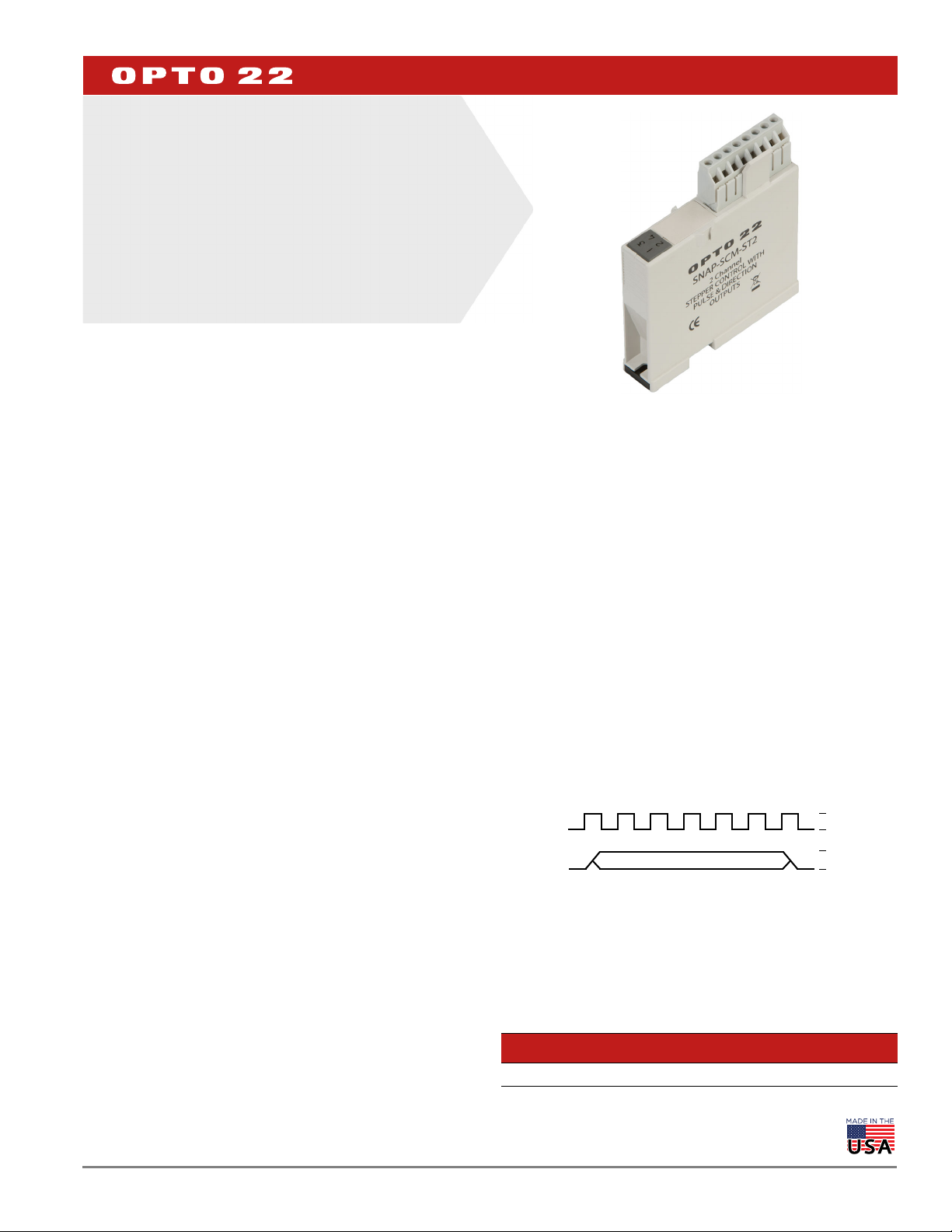
SNAP-SCM-ST2 Module
SNAP-SCM-ST2 PULSE OUTPUT
>>>
+Pulse
+Direction
+5 v
0 v
+5 v
0 v
MODULE
Features
Suited for pulse/direction applications with a frequency
range of 0.13–50,000 Hz
Dual outputs
Software configurable
DESCRIPTION
The SNAP-SCM-ST2 pulse output module is a two-channel serial
communication module that provides pulse and direction signals for
stepper motor drives. Each channel is isolated from the logic side. The
module can either output a constant frequency, or it can ramp from
one frequency to another.
The SNAP-SCM-ST2 links up to two stepper motors which can be
controlled by a SNAP PAC controller running a PAC Control™ strategy.
LED indicators are provided to indicate activity on each port.
The module snaps onto an Opto 22 SNAP PAC mounting rack.
SNAP PAC racks accommodate up to 4, 8, 12, or 16 I/O modules, with
a maximum of 8 serial modules (including SNAP-SCM-ST2) on any
one rack. Because the SNAP-SCM-ST2 module is mounted on these
standard racks with other SNAP I/O modules, you can use the
combination of analog, digital, and serial modules required by your
application at the location where they are needed.
SNAP racks have a retention rail locking system. Use two 4-40 by
½-inch standard machine screws to hold each module securely in
position on the SNAP rack.
NOTE: SNAP-SCM-ST2 modules require a SNAP PAC EB-series brain or
ies
controller with firmware R9.1a or newer. These modules do not
R-ser
work with SNAP PAC SB-series brains nor with legacy brains or controllers.
DATA SHEET
Form 1944-200318
PAGE 1
Commands Supported
The SNAP-SCM-ST2 module supports the following pulse output
commands in PAC Control:
SetPulseFrequency outputs a set frequency until instructed
to do otherwise.
SetPulseSequence ramps from one frequency to another.
ReadPulseFrequency returns a string representing a channel’s
current frequency. This command requires SNAP-SCM-ST2 module
firmware version R1.0d or newer.
These pulse output commands
the Transmit/Receive String command.
“Using the SNAP-SCM-ST2 Module Commands” in the SNAP Serial
Communication Module User’s Guide (form 1191).
are entered in PAC Control using
For more information, see
How the SNAP-SCM-ST2 Outputs Data
The SNAP-SCM-ST2 outputs a specified frequency based on the
command received, as shown here.
The Direction pin can be either +5 VDC or 0 VDC, as determined by
the parameters of the command executed. See “Using the SNAPSCM-ST2 Module Commands” in the SNAP Serial Communication
Module User’s Guide (form 1191).
Part Numbers
Part Description
SNAP-SCM-ST2 SNAP 2-Channel Pulse Output Module
© 2011–2017 Opto 22. All rights reserved . Dimensions and specifications are subject to change. Brand or product names used herein are trademarks or registered trademarks of their respective companies or organizations.
Page 2

SPECIFICATIONS
Frequency Range 0.13–50,000 Hz
Pulse Width Range
Pulse Width Resolution 0–2 Hz, 2–30 Hz, 30–50,000 Hz (See resolution graphs on page 3)
Output Frequency Accuracy
Output Format CMOS/TTL Compatible
Logic Supply Voltage 5.0 VDC
Logic Supply Current 200 mA
Compatible I/O Processors
Duty Cycle Fixed at 50%
Number of Ports per Module 2
Operating Temperature Range -20–60 °C
Storage Temperature Range -30–85 °C
Torque, hold-down screws 4 in-lb (0.45 N-m)
Torque, connector screws 5.26 in-lb (0.6 N-m)
Agency approvals CE, RoHS, DFARS
Warranty 30 months from date of manufacture
1
Pulse Width is equal to one-half the period.
1
3.84 Sec to 10 µSec
To calculate error (in Hz) for the desired frequency, use this equation
and the resolution graphs on page 3the next page:
Frequency Error (+/-) = Desired Frequency - (1 ÷
(Pulse Width Resolution + (1 ÷ Desired Frequency)))
SNAP PAC R-series controllers and EB-series brains with R9.1a or
newer firmware
DATA SHEET
Form 1944-200318
PAGE 2
Pin Assignments
Pin Port Use Description
1
2 Ground Isolated from logic side
3 Direction
4 Ground Isolated from logic side
5
6 Ground Isolated from logic side
7 Direction
8 Ground Isolated from logic side
Pulse Frequency output
A
Pulse Frequency output
B
+5 VDC when asserted
0 VDC when deasserted
+5 VDC when asserted
0 VDC when deasserted
LED Indicators
LED Description
1 Blinks when outputting pulses on channel 1
2 Positive/Negative direction indicator on channel 1
3 Blinks when outputting pulses on channel 2
4 Positive/Negative direction indicator on channel 2
See diagram on page 4 for location of pin 1.
© 2011–2017 Opto 22. All rights reserved. Dimen sions and specifications are subject to change. Brand or product names used herein are trademarks or registered trademarks of their respective companies or organizations.
Page 3

3.50E-05
3.00E-05
2.50E-05
2.00E-05
1.50E-05
1.00E-05
5.00E-06
0.00E+00
0 0.5 1 1.5 2 2.5
Frequency (Hz)
Pulse Width Resolution +/- (s)
Pulse Width Resolution for Frequencies from 0–2 Hz
Equation
3.871×10
-6
Frequency
0.993
Resolution=
2.00E-06
1.80E-06
1.60E-06
1.40E-06
1.20E-06
1.00E-06
8.00E-07
0.00E+00
0 5 10 15 20 25
Frequency (Hz)
Pulse Width Resolution +/- (s)
6.00E-07
4.00E-07
2.00E-07
30 35
Pulse Width Resolution for Frequencies from 2–30 Hz
Equation
3.795×10
-6
Frequency
0.993
Resolution=
1.40E-07
1.20E-07
1.00E-07
8.00E-08
6.00E-08
4.00E-08
2.00E-08
0.00E+00
0 100 200 300 400 50,000
Frequency (Hz)
Pulse Width Resolution +/- (s)
500 533.2
Pulse Width Resolution for Frequencies from 30–50,000 Hz
Transition Points
Frequency Resolution +/- (s)
533.20 7.15430×10
-9
266.60 1.43086×10
-8
177.73 2.14629×10
-8
133.30 2.86172×10
-8
106.64 3.57715×10
-8
88.87 4.29258×10
-8
76.17 5.00801×10
-8
66.65 5.72344×10
-8
59.24 6.43887×10
-8
53.32 7.15430×10
-8
48.47 7.86973×10
-8
44.43 8.58516×10
-8
41.02 9.30060×10
-8
38.09 1.00160×10
-7
35.55 1.07315×10
-7
33.33 1.14469×10
-7
31.36 1.21623×10
-7
29.62 1.28777×10
-7
DATA SHEET
Form 1944-200318
PAGE 3
© 2011–2017 Opto 22. All rights reserved . Dimensions and specifications are subject to change. Brand or product names used herein are trademarks or registered trademarks of their respective companies or organizations.
Page 4

DIMENSIONS
Pin 1
SNAP-SCM-ST2 Pulse Output Module
DATA SHEET
Form 1944-200318
PAGE 4
© 2011–2017 Opto 22. All rights reserved. Dimen sions and specifications are subject to change. Brand or product names used herein are trademarks or registered trademarks of their respective companies or organizations.
Page 5

More about Opto 22
PRODUCTS
Opto 22 develops and manufactures reliable, easy-to-use, open
standards-based hardware and software products. Industrial
automation, process control, building automation, industrial
refrigeration, remote monitoring, data acquisition, and industrial
internet of things (IIoT) applications worldwide all rely on Opto 22.
groov EPIC® System
Opto 22’s groov Edge Programmable
Industrial Controller (EPIC) system gives
you an industrially hardened system with
guaranteed-for-life I/O, a flexible Linux®based processor with gateway functions,
and software for your automation and IIoT
applications.
groov EPIC I/O
groov I/O connects locally to sensors and
equipment with up to 24 channels on each I/O module. Modules
have a spring-clamp terminal strip, integrated wireway, swing-away
cover, and LEDs indicating module health and discrete channel status.
groov I/O is hot swappable, UL Hazardous Locations approved, and
ATEX compliant.
groov EPIC Processor
The heart of the system is the groov EPIC processor. It handles a wide
range of digital, analog, and serial functions for data collection,
remote monitoring, process control, and discrete and hybrid
manufacturing.
In addition, the EPIC provides secure data communications among
physical assets, control systems, software applications, and online
services, both on premises and in the cloud.
Configuring and troubleshooting I/O and networking is easier with
the EPIC’s integrated high-resolution color touchscreen. Authorized
users can manage the system locally on the touchscreen or on a
monitor connected via the HDMI or USB ports.
groov RIO
groov RIO revolutionizes remote I/O by offering a single, compact,
PoE-powered industrial package with web-based configuration,
commissioning, and flow logic software built in, plus support for
multiple OT and IT protocols.
Standing alone, it meets the needs of small, variable I/O count
applications, especially those that require
data logging or data communications,
commonly found in IIoT applications.
groov RIO can also be used with a
Modbus/TCP master or as remote I/O for
a groov EPIC system.
Older products
From solid state relays (our first products)
to world-famous G4 and SNAP I/O, to
SNAP PAC controllers, older Opto 22
products are still supported and still
doing the job at thousands of installations worldwide. You can count
on us to give you the reliability and service you expect, now and in the
future.
QUALITY
Founded in 1974, Opto 22 has established a worldwide reputation for
high-quality products. All are made in the U.S.A. at our manufacturing
facility in Temecula, California.
Because we test each product twice before it leaves our factory rather
than testing a sample of each batch, we can afford to guarantee most
solid-state relays and optically isolated I/O modules for life.
groov EPIC Software
Software included in the groov EPIC processor:
PAC Control engine to run PAC Control and PAC Display
CODESYS Runtime engine to run IEC61131-3 compliant programs
built with CODESYS Development System
Optional access to the Linux operating system through a secure
shell (SSH) to download and run custom applications
groov View for building your own device-independent HMI,
viewable on the touchscreen, PCs, and mobile devices
Node-RED for creating simple logic flows from pre-built nodes
Ignition Edge® from Inductive Automation®, with OPC-UA drivers
to Allen-Bradley®, Siemens®, and other control systems, and MQTT
communications with Sparkplug for efficient IIoT data transfer
© 2001–2020 Opto 22. All rights reserved. Dimensions and specifications are subject to change. Brand or product names used herein are trademarks or registered trademarks of their respective companies or organizations.
Form 1335-200129
 Loading...