

SNAP POWER SUPPLIES
Features
Built-in fuse, ON/OFF power switch, and LED indicator
>
Convenient panel mounting; optional DIN-rail mounting
>
Easy connections
>
Wide input voltage range
>
UL approved
>
Factory Mutual approved (except SNAP-PS5U and
>
SNAP-PS24U)
DESCRIPTION
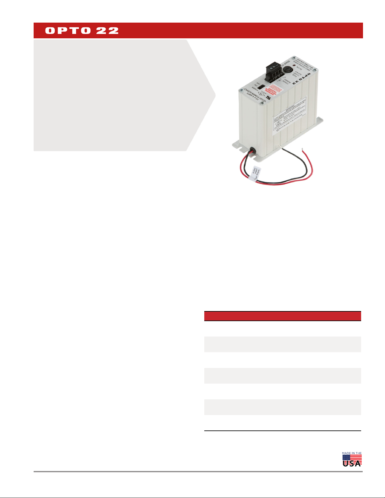
SNAP power supplies provide the best source of AC or DC power for
your Opto 22 SNAP PAC hardware. Packaged in a compact and sturdy
housing, SNAP power supplies include a built-in fuse, an LED status
indicator, and an ON/OFF power switch for ease of use.
DATA SHEET
Form 1120-200129
PAGE 1
SNAP-PS5 power supply
The SNAP-PS24 and SNAP-PS24U power supplies are designed for
either of two purposes:
To provide primary power for a SNAP PAC S-series controller
To provide 24 volts of DC loop power for SNAP analog modules
mounted on a SNAP PAC rack
The SNAP-PS5, SNAP-PS5-24DC, and SNAP-PS5U power supplies
are designed to provide 5 VDC power for a SNAP PAC rack with an I/O
processor (SNAP PAC brain or R-series controller) and I/O modules
mounted on the rack. The combination of a rack, processor, and
modules is called an I/O unit.
Opto 22 recommends using one SNAP power supply for each I/O unit
and for each controller. Choose the power supply based on the load
required for the I/O unit. See the power requirements tables starting
on page 12 for help in determining the power supplies you need.
Additional information on using power supplies can be found in the
Opto 22 technical note Using Power Supplies with Opto 22 Systems
(form #1271, available on our website,
All SNAP power supplies except the SNAP-PS5-24DC require AC input
power. The SNAP-PS5U and SNAP-PS24U accommodate a wide range
of AC input voltages, from 100 to 250 VAC.
The SNAP-PS5-24DC DC-to-DC power supply requires a 24 VDC input
and is ideal for systems using DC backup power.
Each SNAP power supply can be mounted in one of two ways: next to
the controller or SNAP I/O unit it powers, using the standard
panel-mounting base, or directly on a DIN rail using the optional
35mm DIN-rail adapter.
AC or DC input power connections, as required by the model, are
made to a removable terminal strip on top of the power supply. DC
output power is then ready to be hooked up to the controller or rack
using the attached wiring harness.
SNAP power supplies work with Wired+Wireless™ PACs and I/O units
as well as standard wired PACs and I/O.
Notes for legacy hardware: SNAP power supplies are also
compatible with Ethernet-based SNAP Ultimate, SNAP Ethernet, and
SNAP Simple I/O, and with serial-based SNAP I/O units such as those
with a B3000, SNAP-HA, or SNAP-B3000-MODBUS brain.
Part Numbers
Part Description
SNAP-PS5
SNAP-PS5-24DC
SNAP-PS5U
SNAP-PS24
SNAP-PS24U
SNAP-PSDIN
SNAP-PSUDIN
SNAP Power Supply
120 VAC input; 5 VDC, 4 A output
SNAP Power Supply
24 VDC input; 5 VDC, 4 A output
SNAP Power Supply
100–250 VAC input; 5 VDC, 5 A output
SNAP Power Supply
120 VAC input; 24 VDC, 3/4 A output
SNAP Power Supply
100–250 VAC input; 24 VDC, 1-1/4 A output
35mm DIN-Rail Adapter for SNAP-PS5,
SNAP-PS24, or SNAP-PS5-24DC
35mm DIN-Rail Adapter for SNAP-PS5U or
SNAP-PS24U
© 2001–2020 Opto 22. All rights reserved. Dimensions and specifications are subject to change. Brand or product names used herein are trademarks or registered trademarks of their respective companies or organizations.
Form 1120-200129
SPECIFICATIONS
SNAP-PS5 SNAP-PS5-24DC SNAP-PS5U
Input Voltage 95–130 VAC, 47–63 Hz 18–32 VDC 100–250 VAC, 47–63 Hz
Output Voltage 5.1 ±0.1 VDC 5.1 ±0.1 VDC 5.1 ±0.1 VDC
Output Current 4.0 A 4.0 A 5.0 A
Maximum Input Current Draw 0.4 Amps at 120 VAC 1.3 Amps at 24 VDC 0.5 Amps at 120 VAC
Dimensions
Weight 15 oz. (425.25 g) 15 oz. (425.25 g) 1.9 lbs (863.63 g)
Operating Temperature -20 to 70 °C -20 to 70 °C -20 to 70 °C
Storage Temperature -30 to 85 °C -30 to 85 °C -30 to 85 °C
Torque, connector screws 4.5 in-lb (0.51 N-m) 4.5 in-lb (0.51 N-m) 4.5 in-lb (0.51 N-m)
Fuse
Agency Approvals FM, UL, ATEX, DFARS
Warranty 30 months 30 months 30 months
See the drawings starting on
page 8.
Opto 22 PN: SNAP-FUSE1AB
Vendor PN: GDC-1A (Bussman)
See the drawings starting on
page 8.
Opto 22 PN: SNAP-FUSE2AB
Vendor PN: GDB-2A (Bussman)
FM, UL, CE, ATEX, RoHS,
DFARS
See the drawings on
page 10.
Internal fuse
UL, CE, RoHS, DFARS
DATA SHEET
PAGE 2
SNAP-PS24 SNAP-PS24U
Input Voltage 95–130 VAC, 47–63 Hz 100–250 VAC, 47–63 Hz
Output Voltage 24 ± 0.6 VDC 24 ± 0.1 VDC
Output Current 0.75 A 1.25 A
Maximum Input Current Draw 0.4 Amps @ 120 VAC 0.5 Amps @ 120 VAC
Dimensions
Weight 2.1 lbs (952.54 g) 1.9 lbs (863.63 g)
Operating Temperature -20 to 70 °C -20 to 70 °C
Storage Temperature -30 to 85 °C -30 to 85 °C
Torque, connector screws 4.5 in-lb (0.51 N-m) 4.5 in-lb (0.51 N-m)
Fuse
Agency Approvals FM, UL, CE, RoHS, DFARS UL, CE, RoHS, DFARS
Warranty 30 months 30 months
See drawings starting on
Opto 22 PN: SNAP-FUSE1AB Vendor
PN: GDC-1A (Bussman)
page 8. See drawings on page 10.
Internal fuse
© 2001–2020 Opto 22. All rights reserved. Dimensions and specifications are subject to change. Brand or product names used herein are trademarks or registered trademarks of their respective companies or organizations.

I/O UNIT POWER REQUIREMENTS
The tables starting on page 12 will help you determine the power
supply needs for your system. Copy the power requirements
worksheet and complete one for each distributed I/O unit.
In addition, keep the following power recommendations in mind. For
more help with power supplies, see Opto 22 form #1271, Using Power
Supplies with Opto 22 Systems.
Use a single power supply per rack
In general, we recommend you use an independent, isolated,
regulated power supply locally with each rack. Local isolated supplies
offer these advantages:
Short supply conductors, which minimize losses
Power redundancy, so the failure of a single supply causes only a
single rack failure, not a total system failure
Fewer voltage drops and ground loops (Voltage drops and
subsequent ground loops may occur when power is distributed
over a large system.)
DATA SHEET
Form 1120-200129
PAGE 3
Always use a separate field supply
Use a separate power supply for the field side of the I/O. Using the
rack supply for field actuation and monitoring defeats the isolation
the I/O module offers and therefore increases the chance of a ground
loop within the control system. Additionally, a sudden change of
current on the field side can cause undesirable voltage fluctuations
that may interfere with the controller or I/O unit’s operation.
Power wiring guidelines
Use one power supply per I/O unit.
Use one power supply per controller.
Use 14 AWG wire.
SNAP power supplies have short wires to minimize voltage drop.
Do not extend the length of the wires.
If you power multiple I/O units or controllers from one power
supply, use a star wiring topology. Do not daisy-chain power
wiring from one device to the next.
© 2001–2020 Opto 22. All rights reserved. Dimensions and specifications are subject to change. Brand or product names used herein are trademarks or registered trademarks of their respective companies or organizations.
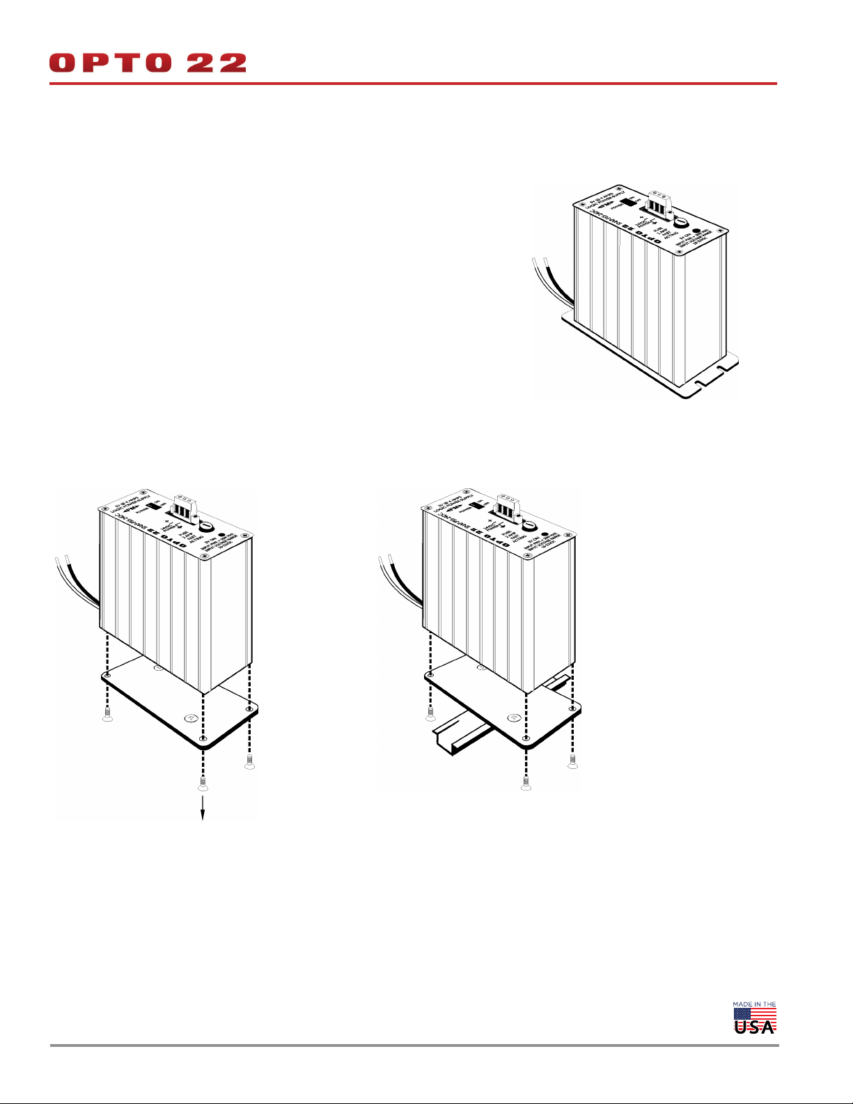
INSTALLATION
Panel Mounting (standard)
Mount the SNAP power supply in a location where the attached red and black power
wires will reach the “+” and “-” power terminals on the SNAP mounting rack or controller.
Do not extend the wires.
DIN-Rail Mounting (optional)
1. For 35mm DIN-rail mounting, remove the four screws that fasten the panel mounting
base plate to the power supply. Keep screws in a safe place.
2. Remove panel mounting base plate.
3. In place of the panel mounting base plate, use the four screws removed in step 1 to
fasten the DIN-rail adapter (purchased separately) to the power supply.
4. Mount the SNAP power supply on the DIN rail (next to the power connector on the
I/O unit).
DATA SHEET
Form 1120-200129
PAGE 4
© 2001–2020 Opto 22. All rights reserved. Dimensions and specifications are subject to change. Brand or product names used herein are trademarks or registered trademarks of their respective companies or organizations.
WIRING—PRIMARY POWER SUPPLY
DATA SHEET
Form 1120-200129
PAGE 5
Wiring to a Standalone Controller
1. For a controller, check the controller’s specifications in its data
sheet or user’s guide to make sure you have the correct power
supply for the controller’s requirements.
2. Follow directions in the controller’s user’s guide to wire the power
supply to the controller. The power supply’s red (or
white-and-red) wire is the positive wire; the black (or
white-and-black) wire is the negative wire.
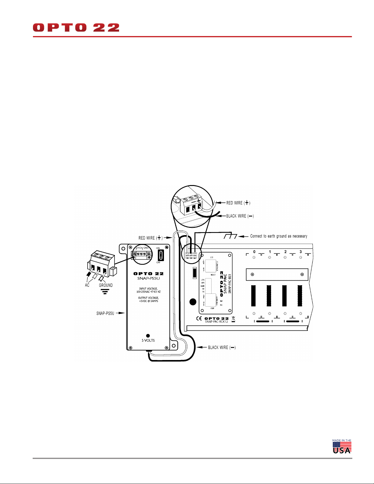
Wiring to a SNAP I/O Unit
1. Using the power terminals on the SNAP mounting rack, attach the
red wire to the “+” terminal and the black wire to the “-” terminal.
2. For the SNAP-PS5 (not illustrated): Using the removable input
power connector on top of the power supply, apply 120 volts AC
power between the two terminals marked “AC.” The ground
terminal should be connected to ground.
3. For the SNAP-PS5-24DC (not illustrated): Using the removable
input power connector on top of the power supply, apply 24 volts
DC power between the two terminals marked “±DC.” The ground
terminal should be connected to ground.
4. For the SNAP-PS5U (illustrated below): Using the removable
input power connector on top of the power supply, apply 100–
250 volts AC power between the two terminals marked “AC.” The
ground terminal should be connected to ground.
© 2001–2020 Opto 22. All rights reserved. Dimensions and specifications are subject to change. Brand or product names used herein are trademarks or registered trademarks of their respective companies or organizations.

WIRING—LOOP POWER SUPPLY
DATA SHEET
Form 1120-200129
PAGE 6
1. Mount the SNAP-PS24 or SNAP-PS24U power supply in a location
where the attached output power wires will reach the field
connector for SNAP analog modules or the terminal strip on SNAP
mounting racks that have the additional field wiring terminal
strips.
2. The white-and-red wire is the positive wire (24 VDC). The
white-and-black wire is the negative wire (24 VDC return). For
specific loop power wiring information, see Opto 22 forms #1065
analog modules (see Figure 1 below), or refer to form #0784 for
SNAP racks that have the additional field wiring terminal strip (see
Figure 2). See the next page for similar SNAP-PS24U wiring
diagrams.
3. Using the removable input power connector on top of the power
supply, apply 120 volts of AC power between the two terminals
marked “AC.” The ground terminal should be connected to
ground.
and #1066 if wiring directly to the field connectors on SNAP
Figure 1. SNAP-PS24 Used as a Loop Supply with the SNAP PAC System
This diagram shows the SNAP-PS24 used as the loop supply and a SNAP-PS5 used as the primary power supply.
Figure 2. SNAP-PS24 Used as a Loop Supply with Legacy Hardware
The SNAP-PS24 is used as the loop supply; a SNAP-PS5 is used as the primary power supply.
© 2001–2020 Opto 22. All rights reserved. Dimensions and specifications are subject to change. Brand or product names used herein are trademarks or registered trademarks of their respective companies or organizations.

WIRING—LOOP SUPPLY (CONTINUED)
Figure 1. SNAP-PS24U Used as a Loop Supply with the SNAP PAC System
This diagram shows the SNAP-PS24U used as the loop supply and a SNAP-PS5U used as the primary power supply.
DATA SHEET
Form 1120-200129
PAGE 7
Figure 2. SNAP-PS24U Used as a Loop Supply with Legacy Hardware
The SNAP-PS24U is used as the loop supply; a SNAP-PS5U is used as the primary power supply.
© 2001–2020 Opto 22. All rights reserved. Dimensions and specifications are subject to change. Brand or product names used herein are trademarks or registered trademarks of their respective companies or organizations.

DIMENSIONS—SNAP-PS5, SNAP-PS24, AND SNAP-PS5-24DC
Panel Mount
DATA SHEET
Form 1120-200129
PAGE 8
The length of the red and black leads is 8.00 inches +/- .50 inches.
© 2001–2020 Opto 22. All rights reserved. Dimensions and specifications are subject to change. Brand or product names used herein are trademarks or registered trademarks of their respective companies or organizations.

DIMENSIONS—SNAP-PS5, SNAP-PS24, AND SNAP-PS5-24DC
With DIN-Rail Adapter
DATA SHEET
Form 1120-200129
PAGE 9
© 2001–2020 Opto 22. All rights reserved. Dimensions and specifications are subject to change. Brand or product names used herein are trademarks or registered trademarks of their respective companies or organizations.

DIMENSIONS—SNAP-PS5U AND SNAP-PS24U
Panel Mount
SNAP-PS5U is shown; SNAP-PS24U has the same dimensions.
DATA SHEET
Form 1120-200129
PAGE 10
The length of the red and black leads is 9.00 inches +/- .50 inches.
© 2001–2020 Opto 22. All rights reserved. Dimensions and specifications are subject to change. Brand or product names used herein are trademarks or registered trademarks of their respective companies or organizations.

DIMENSIONS—SNAP-PSDIN
DATA SHEET
Form 1120-200129
PAGE 11
DIMENSIONS—SNAP-PSUDIN
© 2001–2020 Opto 22. All rights reserved. Dimensions and specifications are subject to change. Brand or product names used herein are trademarks or registered trademarks of their respective companies or organizations.

POWER REQUIREMENTS TABLES
Opto 22 recommends using one power supply per I/O unit and one power supply per controller. See “I/O Unit Power
Requirements” on page 3 for additional
To determine power requirements for products not listed in these tables, see the data sheets for the individual products.
MPORTANT NOTE: For a SNAP-PS5 or a SNAP-PS5-24DC power supply, the total power required must not exceed 4 amps.
For a SNAP-PS5U, the total power required must not exceed 5 amps.
Controller Power Requirements
Standalone Controller or adapter card Power Req (VDC) Power Req. (Amps)
SNAP PAC S-series controllers (wired) 8–32 VDC* 10 VA**
Wired+Wireless S-series PACs 8–32 VDC 11.3 VA
SNAP-LCSX or -LCSX-PLUS controller 5 VDC 0.500
SNAP-LCM4 controller 5 VDC 1.000
M4-SENET-100 adapter card 5 VDC 1.000
M4SARC adapter card 5 VDC 0.200
M4DUALARC adapter card 5 VDC 0.150
Legacy hardware
M4SARCF adapter card 5 VDC 0.250
M4SARCFR adapter card 5 VDC 0.350
* SNAP-PAC-S1 controllers with serial numbers below 500,000 use 8–24 VDC.
** Uses 1 A if powered at 10V. To determine amps required, divide 10 by the number of
volts applied. Example: 10 / 24 V = 0.417 A (24 VDC input requires 0.417 A)
DATA SHEET
Form 1120-200129
PAGE 12
I/O Processor (Brain or On-the-Rack Controller) Power Requirements
Processor (Brain or Rack-mounted Controller) Power Req. (Amps)*
SNAP PAC R-series controllers (all wired models) 1.200
SNAP PAC R-series controllers (Wired+Wireless) 1.500
SNAP PAC EB and SB brains (all wired models) 0.750
SNAP PAC EB brains (Wired+Wireless) 1.000
SNAP Ultimate controller/brains (all models) 1.000
SNAP Ethernet brains 0.800
SNAP Simple I/O brains 0.500
B3000 (serial SNAP brain)
SNAP-D64RS
SNAP-B3000-Modbus
SNAP ARCNET brains
Legacy hardware
SNAP-B4
SNAP-B6
*Current from 5-volt supply
(Continued on following page)
0.500
1.000
1.000
1.500 if terminated
© 2001–2020 Opto 22. All rights reserved. Dimensions and specifications are subject to change. Brand or product names used herein are trademarks or registered trademarks of their respective companies or organizations.

POWER REQUIREMENTS TABLES (CONTINUED)
I/O Unit (Processor, Rack, I/O Modules) Power Requirements Worksheet
I/O Unit (Processor, Rack, I/O Modules) Power Requirements Worksheet
X Power
Item Quantity
Item Quantity
SNAP processor (Enter Amps from Processor Power Require-
SNAP processor (Enter Amps from Processor Power Requirements table)
ments table)
SNAP-IDC5-SW digital input module
SNAP-IDC5-SW digital input module
SNAP-IDC5-SW-NC digital input module
SNAP-IDC5-SW-NC digital input module
SNAP-AITM-8 analog input module
SNAP-AITM-8 analog input module
Isolated analog input and output modules (part numbers ending
Isolated analog input and output modules (part numbers ending
in -i or iSRC) except SNAP-AITM-4i
in -i or iSRC) except SNAP-AITM-4i
All other 4-channel digital input and output modules except
All other 4-channel digital input and output modules except
mechanical relay outputs (not high-density digital modules)
mechanical relay outputs (not high-density digital modules)
SNAP mechanical power relay output modules
SNAP mechanical power relay output modules
SNAP-AICTD, AICTD-43 analog input modules
SNAP-AICTD, AICTD-43 analog input modules
High-density digital input and output modules
High-density digital input and output modules
SNAP-AIMA-32, SNAP-AIMA-iH4, SNAP-AIV-32, and
SNAP-AIMA-32, SNAP-AIMA-iH4, SNAP-AIV-32, and
SNAP-AITM-4i analog input modules
SNAP-AITM-4i analog input modules
All analog output modules except SNAP-AOA-iSRC and
All analog output modules except SNAP-AOA-iSRC and
SNAP-AOD-29-HFi
SNAP-AOD-29-HFi
SNAP-AOD-29-HFi 0.300
SNAP-AOD-29-HFi 0.300
SNAP-AIPM power monitoring module
SNAP-AIPM power monitoring module
SNAP-AIPM-3, SNAP-AIPM-3V power monitoring modules
SNAP-AIPM-3, SNAP-AIPM-3V power monitoring modules
SNAP-AILC and AILC-2 load cell modules
SNAP-AILC and AILC-2 load cell modules
SNAP-AIRTD-8U analog input module
SNAP-AIRTD-8U analog input module
SNAP-AIARMS analog input module
SNAP-AIARMS analog input module
SNAP-AIVRMS analog input module
SNAP-AIVRMS analog input module
SNAP-AICTD-8
SNAP-AICTD-8
SNAP-AIMA, AIMA-4
SNAP-AIMA, AIMA-4
SNAP-AITM and AITM-2 analog input modules
SNAP-AITM and AITM-2 analog input modules
SNAP-AIMV-4
SNAP-AIMV-4
SNAP-AIV, AIV-4
SNAP-AIV, AIV-4
SNAP-AIRTD analog input module
SNAP-AIRTD analog input module
SNAP-AIR40K-4
SNAP-AIR40K-4
SNAP-AIR400K-8
SNAP-AIR400K-8
SNAP-AIRATE analog input module
SNAP-AIRATE analog input module
SNAP-AIRATE-HFi analog input module 0.210
SNAP-AIRATE-HFi analog input module 0.210
SNAP-SCM-ST2 and SNAP-SCM-SSI serial modules
SNAP-SCM-ST2 and SNAP-SCM-SSI serial modules
SNAP-SCM-232, SNAP-SCM-485-422, SNAP-SCM-PROFI
SNAP-SCM-232, SNAP-SCM-485-422, SNAP-SCM-PROFI
SNAP-SCM-MCH16 not powering a breakout board
SNAP-SCM-MCH16 not powering a breakout board
SNAP-SCM-MCH16 powering a breakout board
SNAP-SCM-MCH16 powering a breakout board
Total
Total
4
4
analog input module
analog input module
3
3
, and AIMA-84 analog input modules
, and AIMA-84 analog input modules
3
3
and AIMV2-43 analog input modules
and AIMV2-43 analog input modules
3
3
, and AIV-84 analog input modules
, and AIV-84 analog input modules
3
3
analog input module
analog input module
4
4
analog input module
analog input module
4
4
4
4
4
4
4
4
3
3
4
4
3
3
4
4
4
4
3
3
2
2
2
2
1
1
X Power
Req. (Amps)
Req. (Amps)
0.200
0.200
0.050
0.050
0.160
0.160
0.150
0.150
0.100
0.100
0.120
0.120
0.135
0.135
0.170
0.170
0.190
0.190
0.200
0.200
0.250
0.250
0.700
0.700
Total Power
Total Power
Required (Amps)
Required (Amps)
DATA SHEET
Form 1120-200129
PAGE 13
1
1
1 Current from 5-volt supply
1 Current from 5-volt supply
2 Can be used with SNAP PAC R-series controllers and SNAP PAC brains, SNAP Simple, and SNAP Ultimate
2 Can be used with SNAP PAC R-series controllers and SNAP PAC brains, SNAP Simple, and SNAP Ultimate
3 Can be used with SNAP PAC R-series controllers and SNAP PAC brains, SNAP Simple, SNAP Ethernet, and
3 Can be used with SNAP PAC R-series controllers and SNAP PAC brains, SNAP Simple, SNAP Ethernet, and
SNAP Ultimate
SNAP Ultimate
4 Can be used with SNAP PAC systems only
4 Can be used with SNAP PAC systems only
© 2001–2020 Opto 22. All rights reserved. Dimensions and specifications are subject to change. Brand or product names used herein are trademarks or registered trademarks of their respective companies or organizations.

More about Opto 22
PRODUCTS
Opto 22 develops and manufactures reliable, easy-to-use, open
standards-based hardware and software products. Industrial
automation, process control, building automation, industrial
refrigeration, remote monitoring, data acquisition, and industrial
internet of things (IIoT) applications worldwide all rely on Opto 22.
groov EPIC® System
Opto 22’s groov Edge Programmable
Industrial Controller (EPIC) system gives
you an industrially hardened system with
guaranteed-for-life I/O, a flexible Linux®based processor with gateway functions,
and software for your automation and IIoT
applications.
groov EPIC I/O
groov I/O connects locally to sensors and
equipment with up to 24 channels on each I/O module. Modules
have a spring-clamp terminal strip, integrated wireway, swing-away
cover, and LEDs indicating module health and discrete channel status.
groov I/O is hot swappable, UL Hazardous Locations approved, and
ATEX compliant.
groov EPIC Processor
The heart of the system is the groov EPIC processor. It handles a wide
range of digital, analog, and serial functions for data collection,
remote monitoring, process control, and discrete and hybrid
manufacturing.
In addition, the EPIC provides secure data communications among
physical assets, control systems, software applications, and online
services, both on premises and in the cloud.
Configuring and troubleshooting I/O and networking is easier with
the EPIC’s integrated high-resolution color touchscreen. Authorized
users can manage the system locally on the touchscreen or on a
monitor connected via the HDMI or USB ports.
groov RIO
groov RIO revolutionizes remote I/O by offering a single, compact,
PoE-powered industrial package with web-based configuration,
commissioning, and flow logic software built in, plus support for
multiple OT and IT protocols.
Standing alone, it meets the needs of small, variable I/O count
applications, especially those that require
data logging or data communications,
commonly found in IIoT applications.
groov RIO can also be used with a
Modbus/TCP master or as remote I/O for
a groov EPIC system.
Older products
From solid state relays (our first products)
to world-famous G4 and SNAP I/O, to
SNAP PAC controllers, older Opto 22
products are still supported and still
doing the job at thousands of installations worldwide. You can count
on us to give you the reliability and service you expect, now and in the
future.
QUALITY
Founded in 1974, Opto 22 has established a worldwide reputation for
high-quality products. All are made in the U.S.A. at our manufacturing
facility in Temecula, California.
Because we test each product twice before it leaves our factory rather
than testing a sample of each batch, we can afford to guarantee most
solid-state relays and optically isolated I/O modules for life.
groov EPIC Software
Software included in the groov EPIC processor:
PAC Control engine to run PAC Control and PAC Display
CODESYS Runtime engine to run IEC61131-3 compliant programs
built with CODESYS Development System
Optional access to the Linux operating system through a secure
shell (SSH) to download and run custom applications
groov View for building your own device-independent HMI,
viewable on the touchscreen, PCs, and mobile devices
Node-RED for creating simple logic flows from pre-built nodes
Ignition Edge® from Inductive Automation®, with OPC-UA drivers
to Allen-Bradley®, Siemens®, and other control systems, and MQTT
communications with Sparkplug for efficient IIoT data transfer
© 2001–2020 Opto 22. All rights reserved. Dimensions and specifications are subject to change. Brand or product names used herein are trademarks or registered trademarks of their respective companies or organizations.
Form 1335-200129
 Loading...